

Interrupt Controller
3.1Introduction
The interrupt controller provides a simple software interface to the interrupt system. In this specification certain interrupt bits are defined for the basic functionality required in a system design, whilst the remaining bits are available for use by other devices in any particular implementation.
In an ARM system two levels of interrupt are available, FIQ (Fast Interrupt Request) for fast, low latency interrupt handling and IRQ (Interrupt Request) for more general interrupts.
Ideally, in an ARM system, only a single FIQ source would be in use at any particular time. This provides a true low-latency interrupt, as a single source ensures that the interrupt service routine may be executed directly without the need to determine the source of the interrupt. It also reduces the interrupt latency as the extra banked registers, which are available for FIQ interrupts, may be used to maximum efficiency by preventing the need for a context save.
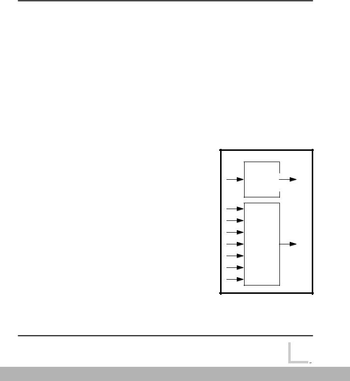
Separate interrupt controllers are used for FIQ and IRQ, the difference is that only a single bit position is defined for FIQ, which is intended for use by a single interrupt source, whilst 32 bits are available in the IRQ controller. A number of methods may be used to extend the IRQ interrupt controller, should more than 32 interrupt source be required.
FIQ
Control
IRQ
Control
Figure 3-1: FIQ and IRQ interrupts
3-2 |
Reference Peripherals Specification |
|
|
|
ARM DDI 0062D |
|
|
|
|
|
|
Open Access

Interrupt Controller
The IRQ interrupt controller uses a bit position for each different interrupt source and bit positions are defined for a software programmed interrupt, a communications channel and timers. Bit 0 is unassigned in the IRQ controller so that it may share the same interrupt source as the FIQ controller.
All interrupt source inputs shall be active HIGH and level sensitive, any inversion or latching required to provide edge sensitivity must be provided at the generating source of the interrupt.
No hardware priority scheme is provided, neither is any form of interrupt vectoring, as these functions can be provided in software.
A programmed interrupt register is also provided to generate an interrupt under software control. This may typically be used to downgrade a FIQ interrupt to a IRQ interrupt.
|
|
Reference Peripherals Specification |
3-3 |
|
|
ARM DDI 0062D |
|
|
|
|
|
Open Access