

CHAPTER
DSP Software
4
DSP applications are usually programmed in the same languages as other science and engineering tasks, such as: C, BASIC and assembly. The power and versatility of C makes it the language of choice for computer scientists and other professional programmers. On the other hand, the simplicity of BASIC makes it ideal for scientists and engineers who only occasionally visit the programming world. Regardless of the language you use, most of the important DSP software issues are buried far below in the realm of whirling ones and zeros. This includes such topics as: how numbers are represented by bit patterns, round-off error in computer arithmetic, the computational speed of different types of processors, etc. This chapter is about the things you can do at the high level to avoid being trampled by the low level internal workings of your computer.
Computer Numbers
Digital computers are very proficient at storing and recalling numbers; unfortunately, this process isn't without error. For example, you instruct your computer to store the number: 1.41421356. The computer does its best, storing the closest number it can represent: 1.41421354. In some cases this error is quite insignificant, while in other cases it is disastrous. As another illustration, a classic computational error results from the addition of two numbers with very different values, for example, 1 and 0.00000001. We would like the answer to be 1.00000001, but the computer replies with 1. An understanding of how computers store and manipulate numbers allows you to anticipate and correct these problems before your program spits out meaningless data.
These problems arise because a fixed number of bits are allocated to store each number, usually 8, 16, 32 or 64. For example, consider the case where eight bits are used to store the value of a variable. Since there are 28 = 256 possible bit patterns, the variable can only take on 256 different values. This is a fundamental limitation of the situation, and there is nothing we can do about it. The part we can control is what value we declare each bit pattern
67
68 |
The Scientist and Engineer's Guide to Digital Signal Processing |
to represent. In the simplest cases, the 256 bit patterns might represent the integers from 0 to 255, 1 to 256, -127 to 128, etc. In a more unusual scheme, the 256 bit patterns might represent 256 exponentially related numbers: 1, 10, 100, 1000, þ, 10254, 10255. Everyone accessing the data must understand what value each bit pattern represents. This is usually provided by an algorithm or formula for converting between the represented value and the corresponding bit pattern, and back again.
While many encoding schemes are possible, only two general formats have become common, fixed point (also called integer numbers) and floating point (also called real numbers). In this book's BASIC programs, fixed point variables are indicated by the % symbol as the last character in the name, such as: I%, N%, SUM%, etc. All other variables are floating point, for example: X, Y, MEAN, etc. When you evaluate the formats presented in the next few pages, try to understand them in terms of their range (the largest and smallest numbers they can represent) and their precision (the size of the gaps between numbers).
Fixed Point (Integers)
Fixed point representation is used to store integers, the positive and negative whole numbers: þ&3, &2, &1, 0, 1, 2, 3,þ. High level programs, such as C and BASIC, usually allocate 16 bits to store each integer. In the simplest case, the 216 ' 65,536 possible bit patterns are assigned to the numbers 0 through 65,535. This is called unsigned integer format, and a simplified example is shown in Fig. 4-1 (using only 4 bits per number). Conversion between the bit pattern and the number being represented is nothing more than changing between base 2 (binary) and base 10 (decimal). The disadvantage of unsigned integer is that negative numbers cannot be represented.
Offset binary is similar to unsigned integer, except the decimal values are shifted to allow for negative numbers. In the 4 bit example of Fig. 4-1, the decimal numbers are offset by seven, resulting in the 16 bit patterns corresponding to the integer numbers -7 through 8. In this same manner, a 16 bit representation would use 32,767 as an offset, resulting in a range between -32,767 and 32,768. Offset binary is not a standardized format, and you will find other offsets used, such 32,768. The most important use of offset binary is in ADC and DAC. For example, the input voltage range of -5v to 5v might be mapped to the digital numbers 0 to 4095, for a 12 bit conversion.
Sign and magnitude is another simple way of representing negative integers. The far left bit is called the sign bit, and is made a zero for positive numbers, and a one for negative numbers. The other bits are a standard binary representation of the absolute value of the number. This results in one wasted bit pattern, since there are two representations for zero, 0000 (positive zero) and 1000 (negative zero). This encoding scheme results in 16 bit numbers having a range of -32,767 to 32,767.
Chapter 4- DSP Software |
69 |
UNSIGNED |
|
OFFSET |
|
SIGN AND |
|
TWO'S |
|||||||||
INTEGER |
|
BINARY |
MAGNITUDE |
COMPLEMENT |
|||||||||||
Decimal |
|
Bit Pattern |
|
Decimal |
|
Bit Pattern |
|
Decimal |
|
Bit Pattern |
|
Decimal |
|
Bit Pattern |
|
|
|
|
|
||||||||||||
|
|
|
|
|
|
|
|
|
|
|
|
|
|
|
|
15 |
|
1111 |
8 |
|
1111 |
|
7 |
|
0111 |
7 |
|
0111 |
|||
14 |
|
1110 |
7 |
|
1110 |
|
6 |
|
0110 |
6 |
|
0110 |
|||
13 |
|
1101 |
6 |
|
1101 |
|
5 |
|
0101 |
5 |
|
0101 |
|||
12 |
|
1100 |
5 |
|
1100 |
|
4 |
|
0100 |
4 |
|
0100 |
|||
11 |
|
1011 |
4 |
|
1011 |
|
3 |
|
0011 |
3 |
|
0011 |
|||
10 |
|
1010 |
3 |
|
1010 |
|
2 |
|
0010 |
2 |
|
0010 |
|||
9 |
|
1001 |
2 |
|
1001 |
|
1 |
|
0001 |
1 |
|
0001 |
|||
8 |
|
1000 |
1 |
|
1000 |
|
0 |
|
0000 |
0 |
|
0000 |
|||
7 |
|
0111 |
0 |
|
0111 |
|
0 |
|
1000 |
-1 |
|
1111 |
|||
6 |
|
0110 |
-1 |
|
0110 |
|
-1 |
|
1001 |
-2 |
|
1110 |
|||
5 |
|
0101 |
-2 |
|
0101 |
|
-2 |
|
1010 |
-3 |
|
1101 |
|||
4 |
|
0100 |
-3 |
|
0100 |
|
-3 |
|
1011 |
-4 |
|
1100 |
|||
3 |
|
0011 |
-4 |
|
0011 |
|
-4 |
|
1100 |
-5 |
|
1011 |
|||
2 |
|
0010 |
-5 |
|
0010 |
|
-5 |
|
1101 |
-6 |
|
1010 |
|||
1 |
|
0001 |
-6 |
|
0001 |
|
-6 |
|
1110 |
-7 |
|
1001 |
|||
0 |
|
0000 |
-7 |
|
0000 |
|
-7 |
|
1111 |
-8 |
|
1000 |
|||
|
|
|
|
||||||||||||
16 bit range: |
|
16 bit range |
|
16 bit range |
|
16 bit range |
|||||||||
0 to 65,535 |
-32,767 to 32,768 |
-32,767 to 32,767 |
-32,768 to 32,767 |
||||||||||||
FIGURE 4-1
Common formats for fixed point (integer) representation. Unsigned integer is a simple binary format, but cannot represent negative numbers. Offset binary and sign & magnitude allow negative numbers, but they are difficult to implement in hardware. Two's complement is the easiest to design hardware for, and is the most common format for general purpose computing.
These first three representations are conceptually simple, but difficult to implement in hardware. Remember, when A=B+C is entered into a computer program, some hardware engineer had to figure out how to make the bit pattern representing B, combine with the bit pattern representing C, to form the bit pattern representing A.
Two's complement is the format loved by hardware engineers, and is how integers are usually represented in computers. To understand the encoding pattern, look first at decimal number zero in Fig. 4-1, which corresponds to a binary zero, 0000. As we count upward, the decimal number is simply the binary equivalent (0 = 0000, 1 = 0001, 2 = 0010, 3 = 0011, etc.). Now, remember that these four bits are stored in a register consisting of 4 flip-flops. If we again start at 0000 and begin subtracting, the digital hardware automatically counts in two's complement: 0 = 0000, -1 = 1111, -2 = 1110, -3 = 1101, etc. This is analogous to the odometer in a new automobile. If driven forward, it changes: 00000, 00001, 00002, 00003, and so on. When driven backwards, the odometer changes: 00000, 99999, 99998, 99997, etc.
Using 16 bits, two's complement can represent numbers from -32,768 to 32,767. The left most bit is a 0 if the number is positive or zero, and a 1 if the number is negative. Consequently, the left most bit is called the sign bit, just as in sign & magnitude representation. Converting between decimal and two's complement is straightforward for positive numbers, a simple decimal to binary
70 |
The Scientist and Engineer's Guide to Digital Signal Processing |
conversion. For negative numbers, the following algorithm is often used:
(1) take the absolute value of the decimal number, (2) convert it to binary,
(3)complement all of the bits (ones become zeros and zeros become ones),
(4)add 1 to the binary number. For example: -5 6 5 6 0101 6 1010 6 1011. Two's complement is hard for humans, but easy for digital electronics.
Floating Point (Real Numbers)
The encoding scheme for floating point numbers is more complicated than for fixed point. The basic idea is the same as used in scientific notation, where a mantissa is multiplied by ten raised to some exponent. For instance, 5.4321 × 10⁶, where 5.4321 is the mantissa and 6 is the exponent. Scientific notation is exceptional at representing very large and very small numbers. For example: 1.2 × 1050, the number of atoms in the earth, or 2.6 × 10& 23, the distance a turtle crawls in one second, compared to the diameter of our galaxy. Notice that numbers represented in scientific notation are normalized so that there is only a single nonzero digit left of the decimal point. This is achieved by adjusting the exponent as needed.
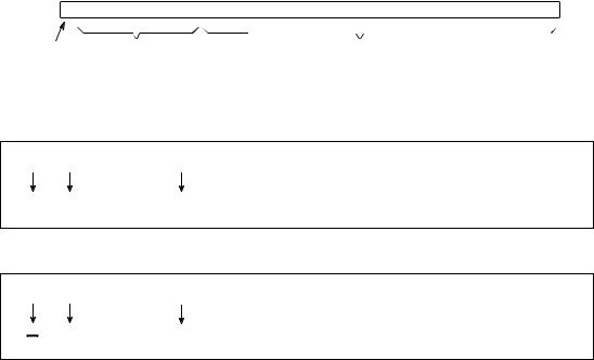
Floating point representation is similar to scientific notation, except everything is carried out in base two, rather than base ten. While several similar formats are in use, the most common is ANSI/IEEE Std. 754-1985. This standard defines the format for 32 bit numbers called single precision, as well as 64 bit numbers called double precision. As shown in Fig. 4-2, the 32 bits used in single precision are divided into three separate groups: bits 0 through 22 form the mantissa, bits 23 through 30 form the exponent, and bit 31 is the sign bit. These bits form the floating point number, v, by the following relation:
EQUATION 4-1
Equation for converting a bit pattern into a
floating point number. The number is v ' (& 1)S × M × 2E & 127 represented by v, S is the value of the sign
bit, M is the value of the mantissa, and E is the value of the exponent.
The term: (&1)S , simply means that the sign bit, S, is 0 for a positive number and 1 for a negative number. The variable, E, is the number between 0 and 255 represented by the eight exponent bits. Subtracting 127 from this number allows the exponent term to run from 2& 127 to 2128. In other words, the exponent is stored in offset binary with an offset of 127.
The mantissa, M, is formed from the 23 bits as a binary fraction. For example, the decimal fraction: 2.783, is interpreted: 2 % 7/10 % 8/100 % 3/1000 . The binary fraction: 1.0101, means: 1 % 0/2 % 1/4 % 0/8 % 1/16 . Floating point numbers are normalized in the same way as scientific notation, that is, there is only one nonzero digit left of the decimal point (called a binary point in
|
|
|
|
|
|
|
|
|
|
Chapter 4- DSP Software |
|
|
|
|
|
|
|
|
|
71 |
||||||||||||||
|
|
|
|
|
|
|
|
|
|
|
|
|
|
|
|
|
|
|
|
|
|
|
|
|
|
|
|
|
|
|
|
|
|
|
31 |
30 |
29 |
28 |
27 |
26 |
25 |
24 |
23 |
22 |
21 |
20 |
19 |
18 |
17 |
16 |
15 |
14 |
|
13 |
12 |
11 |
10 |
9 |
8 |
7 |
6 |
5 |
4 |
3 |
2 |
1 |
0 |
||
|
MSB |
|
|
|
|
|
|
LSB MSB |
|
|
|
|
|
|
|
|
|
|
|
|
|
|
|
|
|
|
|
|
|
|
|
LSB |
||
|
EXPONENT |
|
|
|
|
|
|
|
|
|
|
|
|
|
|
|
|
|
|
|
|
|||||||||||||
SIGN |
|
|
|
|
|
|
MANTISSA |
|
|
|
|
|
|
|
|
|
|
|
||||||||||||||||
1 bit |
|
8 bits |
|
|
|
|
|
|
|
|
|
|
|
|
23 bits |
|
|
|
|
|
|
|
|
|
|
|
||||||||
Example 1
0 00000111 11000000000000000000000
% 1.75 × 2(7& 127) ' % 1.316554 × 10& 36
+ |
7 |
0.75 |
Example 2
1 10000001 01100000000000000000000
& 1.375 × 2(129& 127) ' & 5.500000
129 |
0.375 |
FIGURE 4-2
Single precision floating point storage format. The 32 bits are broken into three separate parts, the sign bit, the exponent and the mantissa. Equations 4-1 and 4-2 shows how the represented number is found from these three parts. MSB and LSB refer to “most significant bit” and “least significant bit,” respectively.
base 2). Since the only nonzero number that exists in base two is 1, the leading digit in the mantissa will always be a 1, and therefore does not need to be stored. Removing this redundancy allows the number to have an additional one bit of precision. The 23 stored bits, referred to by the notation: m22, m21, m21,þ, m0 , form the mantissa according to:
EQUATION 4-2 |
|
Algorithm for converting the bit pattern into |
M ' 1.m22m21m20m19 @@@ m2m1m0 |
the mantissa, M, used in Eq. 4-1. |
In other words, M ' 1 % m22 2& 1 % m21 2& 2 % m20 2& 3@@@. If bits 0 through 22 are all zeros, M takes on the value of one. If bits 0 through 22 are all ones, M is
just a hair under two, i.e., 2 &2& 23.
Using this encoding scheme, the largest number that can be represented is:
± (2&2& 23) × 2128 ' ± 6.8 × 1038. Likewise, the smallest number that can be represented is: ± 1.0 × 2& 127 ' ± 5.9 × 10& 39. The IEEE standard reduces this
range slightly to free bit patterns that are assigned special meanings. In particular, the largest and smallest numbers allowed in the standard are