

Advanced_Renderman_Book[torrents.ru]
.pdf130 5 Handling Complexity in Photorealistic Scenes
Figure 5.6 High (top) and low (bottom) detail levels for tree branches and leaves. See also color plate 5.6.
5.3 Level of Detail
Choosing detail ranges that appropriately remove complexity when it is too small to see is also a bit of an art. A good renderer (like PRMan) can do an excellent job of blending based on relative importance, but, nevertheless, the smoothness of transitions in animation largely depends on how carefully the models are constructed. If silhouettes change radically, or surface coloration changes drastically, it may be possible to see the changes, even if they occur smoothly.
Once carefully crafted models are created, the remaining issue is to carefully compute the transition ranges so that the appropriate model is visible at the appropriate size. This is sometimes tricky because the metric, the detail size, is computed in a relatively simplistic way. It is the raster size of the bounding box provided to the Detail call that will change as the bounding box rotates or is seen from different angles, even if the distance from the camera is the same. It must be considered the "worst-case" raster size of the object and may differ significantly from the number of pixels that the object actually appears in.
Notice, however, that while we have mentioned that the detail size is calculated from a bounding box in object space, there are no calculations that actually depend on the object being entirely within the box. The box is not a bound in the classical sense, such as being part of a culling or clipping calculation. In fact, the only thing that the Detail bound is being used for is as a size metric and, indirectly, an importance metric. Once we have realized that this is true, it becomes clear that we should consider the argument to Detail to be a ruler, not a bounding box. And with this ruler we can measure whatever we like to determine importance.
For example, consider a multiresolution model of a tree. One model might be the entire tree in full glory, with detailed twigs and leaf shapes. A second model might have square leaves and no twigs at all. A third model might be a cylinder trunk and some spheres with texture maps representing the leaf canopy. (See Figure 5.6 for an illustration of the first two of these models.) Because trees often have long trunks and sprawling branches, it is easy to imagine that the bounding box around the entire tree is very large and yet very sparsely covered. If the tree grows or bends in the wind, an accurate bounding box would change sizes even though the "importance" of the various models doesn't really change.
Alternatively, consider placing the Detail ruler around a single leaf. If the leaf is large, we need the most detailed model. If the leaf is subpixel, we can't see individual leaves, so we can just use the canopy. This is tantamount to saying that the most relevant indicator of the required amount of visual detail is how big the leaf is on the screen. The visual perception of the leaf becomes the ruler with which we judge the entire model. A taller tree or a bushier tree gets the same importance because the leaves are the same size on each. Figure 5.7 shows a forest scene where this metric was used to measure the importance of a variety of trees at different distances from the camera.
Once the detail ruler is used in this way, surrounding some visual complexity indicator rather than the entire model, it becomes significantly easier to quantify the required transition ranges on models. Detail sizes are tighter and less prone to undesired "angle-dependent" oscillation. Models can be changed significantly, or

5 Handling Complexity in Photorealistic Scenes
Figure 5.7 A forest composed of level-of-detail trees. See also color plate 5.7.
instanced in slightly different versions, without having to recompute the Detai 1Range every time. And good values for DetailRange are quite simply easier for the TD to estimate and finalize in the first place, as they actually measure whatever geometric or shading element is providing the relevant visual complexity and not any irrelevant overall structure or bulk.
5.3.4Using Level of Detail with Procedural Primitives
In some productions that have attempted to use models with varying complexity, but without the advantage of this level of detail feature, it has been incumbent on some (unlucky) TD to painstakingly determine for every shot (or even for every frame of every shot) which representation of each model was the best to use for that particular rendering. It is easy to see that this is a tedious, error-prone, and unglorious task. With level of detail, the renderer is able to determine with very little computation which representations will be used in a particular image and which will have zero importance and can be trivially rejected. This means that there is often no reason not to put all representations of the model in the RIB file of every frame.
However, in those situations where it is very undesirable for any of the too complex representations to exist in the RIB file (for example, when RIB file size
5.3 Level of Detail |
133 |
or RIB file-generation time are serious issues), these issues can be ameliorated by combining level of detail with procedural primitives. When used in combination with the procedural primitive functions, the detailed object descriptions need never be loaded, or even created, if they aren't used. As an example, suppose we have three versions of a particular object, stored in three RIB files named small.rib, medium.rib, and big.rib that represent the underlying object at various levels of detail.
AttributeBegin |
# push the graphics state |
Detail [-1 1 -1 1 -1 1] |
# set up a "ruler" for detail calcs |
DetailRange [0 0 1 4] |
|
Procedural "DelayedReadArchive" [ "small.rib" ] [-1 1 -1 1 -1 1] DetailRange [1 4 256 400]
Procedural "DelayedReadArchive" [ "medium.rib" ] [-1 1 -1 1 -1 1] DetailRange [256 400 le38 le38]
Procedural "DelayedReadArchive" [ "big.rib" ] [-1 1 -1 1 -1 1] AttributeEnd
The Procedural "DelayedReadArchive" geometric primitive acts as a placeholder. The corresponding RIB file is only read when the bounding box given is determined to be potentially visible. If the box is determined to be outside the version's detail range (or otherwise invisible), it will never be read at all. This means that you can create RIB files that include large amounts of geometry without knowing for sure at what level of detail they will be drawn.
Similarly, you could create a modeling system that created RIB representations of objects "on demand," where Procedural "RunProgram" primitives are executed to generate their RIB only when those primitives are discovered to have some relevance in the current frame.

6.1 History
How PhotoRealistic
RenderMan Works
. . . and What You Can Do about It
Pixar's PhotoRealistic RenderMan renderer is an implementation of a scanline rendering algorithm known as the REYES architecture. REYES was developed in the mid-1980s by the Computer Graphics Research Group at Lucasfilm (now Pixar) with the specific goal of creating a rendering algorithm that would be applicable to creating special effects for motion pictures. The algorithm was first described by Cook et al. in their 1987 Siggraph paper "The REYES Image Rendering Architecture." They developed this novel rendering algorithm because they felt that the other algorithms generally in use at the time (polygon z-buffer algorithms, polygon scanline algorithms, and ray tracers) had various flaws and constraints that really limited their use in this venue.
Images used in motion picture special effects need to be photorealistic - that is, appear of such high quality that the audience would believe they were filmed with a real camera. All of the image artifacts that computer graphics researchers had to live with up to this point were unacceptable if the images were going to fool the critical eyes of the movie-going masses. In particular, REYES was designed to overcome the following problems with existing rendering algorithms:
1366 How PhotoRealistic RenderMan Works
■Vast visual complexity: Photographs of the real world contain millions of objects, and every object has minute details that make it look real. CG images must contain the same complexity if they are to blend seamlessly with live camera work.
■Motion blur: Photographs of moving objects naturally exhibit a blur due to the camera shutter being open for a period of time while the object moves through the field of view. Decades of stop-motion special effects failed to take this into account, and the audience noticed.
■Speed and memory limitations: Motion pictures contain over 100,000 frames and are filmed in a matter of days or weeks. Fast computers are expensive, and there is never enough memory (particularly in retrospect). Implementability on special-purpose hardware was a clear necessity.
The resulting design brought together existing work on curved surface primitives and scanline algorithms with revolutionary new work in flexible shading and stochastic antialiasing to create a renderer that could produce images that truly looked like photographs. It was first used in a film titled Young Sherlock Holmes in 1985, drew rave reviews for its use in The Abyss in 1989, and in 1993 was given an Academy Award for contributions to the film industry.
6.2Basic Geometric Pipeline
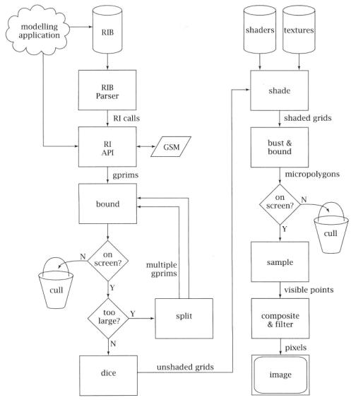
The REYES algorithm is a geometric pipeline, not entirely unlike those found in modern-day hardware graphics engines. What sets it apart is the specific types of geometric operations that occur in the pipeline, and the way that, as the data streams through the system, it gains and retains enough geometric and appearance fidelity that the final result will have very high image quality. Figure 6.1 shows the basic block diagram of the architecture.
The first step, of course, is loading the scene description from the modeler. Typically, the scene description is in a RIB file, loaded from disk. In that case, the RIB file is read by a RIB parser, which calls the appropriate RI routine for each line of the RIB file. Notice that since the RIB file is a simple metafile of the RI API, it is extremely easy to parse. The only minor complexity arises from the handling of parameter list data, which is dependent on the parameter type declarations that appear earlier in the RIB file. Alternatively, a program that is linked to the renderer can call the RI API directly, in which case the parser is simply bypassed.
The second step is the processing of the RenderMan Interface calls themselves. This stage of the pipeline maintains the hierarchical graphics state machine. RI calls fall into two classes: attributes or options that manipulate the graphics state machine, and geometric primitives whose attributes are defined by the then-current version of the graphics state machine. The hierarchical graphics state machine
6.2Basic Geometric Pipeline
Figure 6.1 The REYES rendering pipeline.
is kept in a stack-based data structure within the RI layer. Whenever a geometric primitive arrives, the current top-of-the-stack set of attributes is attached to the primitive before it proceeds into the main REYES geometric processing engine.
1386 How PhotoRealistic RenderMan Works
6.2.1Splitting Loop
The first thing that REYES does to arriving primitives is bound them. The renderer computes a camera-space axis-aligned bounding box that is guaranteed to contain the entire primitive. RenderMan does not contain any unbounded primitives (such as infinite planes), so this is generally straightforward. Most RenderMan primitives have the convex-hull property, which means that the primitive is entirely contained within the volume outlined by the vertices themselves. Primitives that don't have this property (such as Catmull-Rom patches) are converted to equivalent primitives that do (such as Bezier patches).
Next, the bounding box is checked to see if the primitive is actually on-screen. The camera description in the graphics state gives us the viewing volume, a 3D volume of space that contains everything that the camera can see. In the case of perspective projections, this is a rectangular pyramid, bounded on the sides by the perspective projection of the screen window (sometimes called the screen space viewport in graphics texts) and truncated at front and back by the near and far clipping planes; for an orthographic projection this is a simple rectangular box. It is important to note at this point that REYES does not do any global illumination or global intervisibility calculations of any kind. For this reason, any primitive that is not at least partially within the viewing volume cannot contribute to the image in any way and therefore is immediately culled (trivially rejected). Also, any one-sided primitives that are determined to be entirely back facing can be culled at this stage, because they also cannot contribute to the image.
If the primitive is (at least partially) on-screen, its size is tested. If it is deemed "too large" on-screen, according to a metric described later, it is split into smaller primitives. For most parametric primitives, this means cutting the primitive in two (or possibly four) along the central parametric line(s). For primitives that are containers of simpler primitives, such as polyhedra, splitting may mean roughly dividing into two containers each with fewer members. In either case, the idea is to create subprimitives that are simpler and smaller on-screen and more likely to be "small enough" when they are examined. This technique is often called "divide and conquer."
The resulting subprimitives are then dropped independently into the top of the loop, in no particular order, to be themselves bound, cull-tested, and size-tested. Eventually, the progeny of the original primitive will pass the size test and can move on to the next phase called dicing. Dicing converts the small primitive into a common data format called a grid. A grid is a tessellation of the primitive into a rectangular array of quadrilateral facets known as micropolygons (see Figure 6.2). (Because of the geometry of the grid, each facet is actually a tiny bilinear patch, but we call it a micropolygon nonetheless.) The vertices of these facets are the points that will be shaded later, so the facets themselves must be very small in order for the renderer to create the highly detailed, visually complex shading that we have come to expect. Generally, the facets will be on the order of one pixel in area. All primitives, regardless of original type, are converted into grids that look

6.2 Basic Geometric Pipeline |
139 |
|
Figure 6.2 A primitive that is small enough will be diced into a grid of tiny bilinear facets known as micropolygons.
essentially the same to the remainder of the rendering pipeline. At this stage, each grid retains all of the primitive's attributes, and any primitive vertex variables that were attached to the primitive have been correctly interpolated onto every vertex in the grid, but the vertices have not yet been shaded.
6.2.2 Shading
The grid is then passed into the shading system to be shaded. PRMan first evaluates the displacement shader, which may move grid vertices and/or recompute shading normals. Then the surface shader is evaluated. In a typical surface shader, there are calls to diffuse or illuminance somewhere in the code. These routines require the evaluation of all of the light shaders attached to the object. The light shaders run as "coroutines" of the surface shader the first time that they are needed, but their results are cached and reused if they are accessed again (for example, in a subsequent specular call). When the surface shader finishes, it has computed the color and opacity of every grid vertex. Finally, the atmosphere shader is evaluated, making adjustments to the vertex color and opacity to simulate fog or other volumetric effects. The end result of all of these evaluations is that the grid now has final color and opacity assigned to each vertex, and the vertices themselves might be in different places than when originally diced. The other attributes of the original primitive are now mostly superfluous.
The details of the method that the shading system uses to assign color and opacity to each grid vertex are of very little consequence to the REYES pipeline itself but, of course, are of central importance to the users of PRMan. However, readers who are not very familiar with the material in Chapters 7 and 11 will probably want to review those chapters before spending too much time worrying about these details.
PRMan's shading system is an interpreter for the RenderMan Shading Language, which reads the byte-codes in the . slo file previously created by the Shading Language compiler (Hanrahan and Lawson, 1990). Notice that the data structure that the interpreter operates on, a grid, is a bunch of large rectangular arrays of floating-point numbers. For this reason, it may not be surprising that the interpreter
140 6 How PhotoRealistic RenderMan Works
actually executes as a virtual SIMD (single instruction, multiple data) vector math unit. Such vector pipelines were typical in 1980s-vintage supercomputers.
The run-time interpreter reads shader instructions one at a time and executes the operator on all grid vertices. It is important to contrast this scheme with the alternative, which would run the entire shader on the first grid vertex, then run it on the second grid vertex, and so on. The advantages of the breadth-first solution is efficiency. We are able to make near-optimal use of the pipelined floating-point units that appear in modern processors, and we have excellent cache performance due to strong locality of reference. In addition, for uniform variables, the grid has exactly one data value, not nvertices values. As a result, the interpreter is able to compute operations on uniform data exactly once on each grid, saving significantly over the redundant calculations that would be necessary in a depth-first implementation.
However, life is never all gravy. When a conditional or loop instruction is reached, the results may require that not all points on the grid enter the protected block. Because of this, the SIMD controller has run flags, which identify which grid vertices are "active" and which are "inactive" for the current instruction. For any instruction where the run-flag vector has at least one bit on, the instruction is executed, but only on those grid vertices that require it. Other operators such as else, break, and continue manipulate the run flags to ensure that the SIMD execution accurately simulates the depth-first execution.
Another advantage of the SIMD execution model is that neighborhood information is available for most grid vertices (except those on the grid edges), which means that differentials can be computed. These differentials, the difference between values at adjacent grid vertices, substitute for derivatives in all of the Shading Language operators that require derivative information. Those operators, known generically as area operators, include Du, calculatenormal, texture, and their related functions. Notice that grid vertices on edges (actually on two edges, not all four) have no neighbors, so their differential information is estimated. PRMan version 3.8 and lower estimated this poorly, which led to bad grid artifacts in secondderivative calculations. PRMan version 3.9 has a better differential estimator that makes many of these artifacts disappear, but it is still possible to confuse it at inflection points.
6.2.3Texturing
The number and size of texture maps that are typically used in photorealistic scenes are so large that it is impractical to keep more than a small portion of them in memory at one time. For example, a typical frame in a full-screen CGI animation might access texture maps approaching 10 Gb in total size. Fortunately, because this data is not all needed at the highest possible resolution in the same frame, mip-maps can be used to limit this to 200 Mb of texture data actually read. However, even this is more memory than can or needs to be dedicated to such transient data. PRMan has a very sophisticated texture caching system that cycles texture data in as necessary, and keeps the total in-core memory devoted to texture to under 10