

- •Foreword
- •Preface
- •Is This Book for You?
- •How This Book Is Organized
- •How to Use This Book
- •Doing the Exercises
- •Conventions Used in This Book
- •What the Icons Mean
- •About the CD-ROM
- •Other Information
- •Contacting the Author
- •Acknowledgments
- •Contents at a Glance
- •Contents
- •Getting Acquainted with AutoCAD and AutoCAD LT
- •Starting AutoCAD and AutoCAD LT
- •Creating a New Drawing
- •Using the AutoCAD and AutoCAD LT Interface
- •Creating Your First Drawing
- •Saving a Drawing
- •Summary
- •Creating a New Drawing from a Template
- •Working with Templates
- •Opening a Drawing with Default Settings
- •Opening an Existing Drawing
- •Using an Existing Drawing as a Prototype
- •Saving a Drawing Under a New Name
- •Summary
- •The Command Line
- •Command Techniques
- •Of Mice and Pucks
- •Getting Help
- •Summary
- •Typing Coordinates
- •Displaying Coordinates
- •Picking Coordinates on the Screen
- •Locating Points
- •Summary
- •Unit Types
- •Drawing Limits
- •Understanding Scales
- •Inserting a Title Block
- •Common Setup Options
- •The MVSETUP Command
- •Summary
- •Using the LINE Command
- •Drawing Rectangles
- •Drawing Polygons
- •Creating Construction Lines
- •Creating Rays
- •Summary
- •Drawing Circles
- •Drawing Arcs
- •Creating Ellipses and Elliptical Arcs
- •Making Donuts
- •Placing Points
- •Summary
- •Panning
- •The ZOOM Command
- •Aerial View
- •Named Views
- •Tiled Viewports
- •Snap Rotation
- •User Coordinate Systems
- •Isometric Drawing
- •Summary
- •Editing a Drawing
- •Selecting Objects
- •Summary
- •Copying and Moving Objects
- •Using Construction Commands
- •Creating a Revision Cloud
- •Hiding Objects with a Wipeout
- •Double-Clicking to Edit Objects
- •Grips
- •Editing with the Properties Palette
- •Selection Filters
- •Groups
- •Summary
- •Working with Layers
- •Changing Object Color, Linetype, and Lineweight
- •Working with Linetype Scales
- •Importing Layers and Linetypes from Other Drawings
- •Matching Properties
- •Summary
- •Drawing-Level Information
- •Object-Level Information
- •Measurement Commands
- •AutoCAD’s Calculator
- •Summary
- •Creating Single-Line Text
- •Understanding Text Styles
- •Creating Multiline Text
- •Creating Tables
- •Inserting Fields
- •Managing Text
- •Finding Text in Your Drawing
- •Checking Your Spelling
- •Summary
- •Working with Dimensions
- •Drawing Linear Dimensions
- •Drawing Aligned Dimensions
- •Creating Baseline and Continued Dimensions
- •Dimensioning Arcs and Circles
- •Dimensioning Angles
- •Creating Ordinate Dimensions
- •Drawing Leaders
- •Using Quick Dimension
- •Editing Dimensions
- •Summary
- •Understanding Dimension Styles
- •Defining a New Dimension Style
- •Changing Dimension Styles
- •Creating Geometric Tolerances
- •Summary
- •Creating and Editing Polylines
- •Drawing and Editing Splines
- •Creating Regions
- •Creating Boundaries
- •Creating Hatches
- •Creating and Editing Multilines
- •Creating Dlines
- •Using the SKETCH Command
- •Digitizing Drawings with the TABLET Command
- •Summary
- •Preparing a Drawing for Plotting or Printing
- •Creating a Layout in Paper Space
- •Working with Plot Styles
- •Plotting a Drawing
- •Summary
- •Combining Objects into Blocks
- •Inserting Blocks and Files into Drawings
- •Managing Blocks
- •Using Windows Features
- •Working with Attributes
- •Summary
- •Understanding External References
- •Editing an Xref within Your Drawing
- •Controlling Xref Display
- •Managing Xrefs
- •Summary
- •Preparing for Database Connectivity
- •Connecting to Your Database
- •Linking Data to Drawing Objects
- •Creating Labels
- •Querying with the Query Editor
- •Working with Query Files
- •Summary
- •Working with 3D Coordinates
- •Using Elevation and Thickness
- •Working with the User Coordinate System
- •Summary
- •Working with the Standard Viewpoints
- •Using DDVPOINT
- •Working with the Tripod and Compass
- •Getting a Quick Plan View
- •Shading Your Drawing
- •Using 3D Orbit
- •Using Tiled Viewports
- •Defining a Perspective View
- •Laying Out 3D Drawings
- •Summary
- •Drawing Surfaces with 3DFACE
- •Drawing Surfaces with PFACE
- •Creating Polygon Meshes with 3DMESH
- •Drawing Standard 3D Shapes
- •Drawing a Revolved Surface
- •Drawing an Extruded Surface
- •Drawing Ruled Surfaces
- •Drawing Edge Surfaces
- •Summary
- •Drawing Standard Shapes
- •Creating Extruded Solids
- •Drawing Revolved Solids
- •Creating Complex Solids
- •Sectioning and Slicing Solids
- •Using Editing Commands in 3D
- •Editing Solids
- •Listing Solid Properties
- •Summary
- •Understanding Rendering
- •Creating Lights
- •Creating Scenes
- •Working with Materials
- •Using Backgrounds
- •Doing the Final Render
- •Summary
- •Accessing Drawing Components with the DesignCenter
- •Accessing Drawing Content with Tool Palettes
- •Setting Standards for Drawings
- •Organizing Your Drawings
- •Working with Sheet Sets
- •Maintaining Security
- •Keeping Track of Referenced Files
- •Handling Errors and Crashes
- •Managing Drawings from Prior Releases
- •Summary
- •Importing and Exporting Other File Formats
- •Working with Raster Images
- •Pasting, Linking, and Embedding Objects
- •Summary
- •Sending Drawings
- •Opening Drawings from the Web
- •Creating Object Hyperlinks
- •Publishing Drawings
- •Summary
- •Working with Customizable Files
- •Creating Keyboard Shortcuts for Commands
- •Customizing Toolbars
- •Customizing Tool Palettes
- •Summary
- •Creating Macros with Script Files
- •Creating Slide Shows
- •Creating Slide Libraries
- •Summary
- •Creating Linetypes
- •Creating Hatch Patterns
- •Summary
- •Creating Shapes
- •Creating Fonts
- •Summary
- •Working with Menu Files
- •Customizing a Menu
- •Summary
- •Introducing Visual LISP
- •Getting Help in Visual LISP
- •Working with AutoLISP Expressions
- •Using AutoLISP on the Command Line
- •Creating AutoLISP Files
- •Summary
- •Creating Variables
- •Working with AutoCAD Commands
- •Working with Lists
- •Setting Conditions
- •Managing Drawing Objects
- •Getting Input from the User
- •Putting on the Finishing Touches
- •Summary
- •Understanding Local and Global Variables
- •Working with Visual LISP ActiveX Functions
- •Debugging Code
- •Summary
- •Starting to Work with VBA
- •Writing VBA Code
- •Getting User Input
- •Creating Dialog Boxes
- •Modifying Objects
- •Debugging and Trapping Errors
- •Moving to Advanced Programming
- •A Final Word
- •Installing AutoCAD and AutoCAD LT
- •Configuring AutoCAD
- •Starting AutoCAD Your Way
- •Configuring a Plotter
- •System Requirements
- •Using the CD with Microsoft Windows
- •What’s on the CD
- •Troubleshooting
- •Index
652 Part IV Drawing in Three Dimensions
8.To move the camera point, right-click and choose Camera. At the Specify camera
location, or enter angle from XY plane, or [Toggle (angle in)] <11.7252>: prompt, type 8 to lower the camera point slightly. At the Specify camera location, or enter angle in XY plane from X axis, or [Toggle (angle from)] <11.72523>: prompt, move the cursor close to 3 in Figure 22-34, relative to the screen, not the model, and click.
9.Right-click and choose Zoom. At the Specify lens length <35.000mm>: prompt, type 60 to zoom in slightly.
10.Right-click and choose Clip. Right-click and choose Front to set the front clipping plane.
At the Specify distance from target or [set to Eye(camera)] <83'-7 1/2">: prompt, type 13' . The front walls that are blocking the view disappear.
11.Right-click and choose Pan. At the Specify displacement base point: prompt, pick 4 in Figure 22-34, relative to the screen not the drawing. At the Specify second point: prompt, pick 5 relative to the screen. The display moves down.
12.Right-click and choose Hide to hide the drawing. Your drawing should look approximately like Figure 22-35.
13.Press Enter to end the DVIEW command.
14.After all that work, you should save the view. Choose View Named Views. On the Named Views tab, click New. In the New View dialog box, type Perspective 1 in the View Name text box. Click OK. Click OK to return to your drawing.
15.Save your drawing.
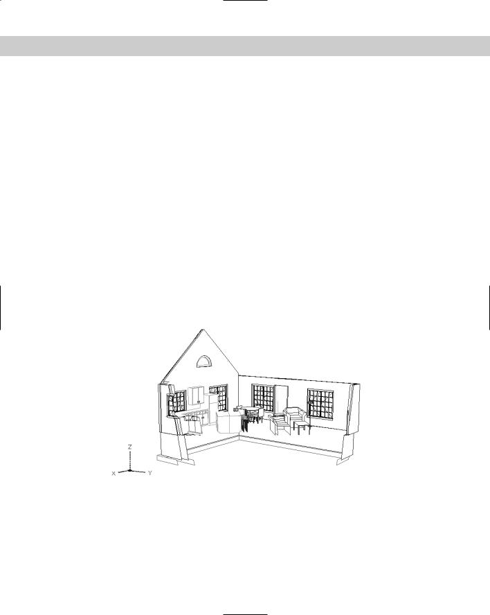
Figure 22-35: The final perspective view.
Laying Out 3D Drawings
Laying out a 3D drawing on a layout tab is an important aspect of viewing a 3D drawing, because the layout determines the final output of the drawing. AutoCAD offers three commands that help you lay out your 3D drawing in paper space layouts — SOLVIEW, SOLDRAW, and SOLPROF. You can find them on the Solids toolbar. (Chapter 17 explains layouts.)
Chapter 22 Viewing 3D Drawings 653
The three commands that I cover in this section are available only in AutoCAD.
Using SOLVIEW to lay out paper space viewports
SOLVIEW automates the process of creating floating viewports and orthogonal views — views at right angles from each other.
 To start SOLVIEW, choose Setup View from the Solids toolbar. SOLVIEW has five options:
UCS enables you to choose the UCS to work from as well as set the scale, center, and clipping corners of a floating viewport. Use this option first. After you choose a UCS, type in a scale. You can change this later if you want. Then SOLVIEW prompts you for the center of the view. Pick a point and wait until the 3D model regenerates. SOLVIEW continues to prompt you for a view center, letting you pick points until you like what you see. Press Enter to continue the prompts. The clipping corners are the corners of the viewport. At the Enter view name: prompt, type a name. SOLVIEW creates the first viewport.
Choose a view name that describes the view, such as Top, Side, or East Elevation. This helps you when you start creating orthogonal views.
Ortho creates orthogonal views. At the Specify side of viewport to project: prompt, pick one of the edges of the first viewport. Again, choose a view center and clip the corners to create the viewport. Type a name for this new view.
If you don’t see the model properly when you pick the view center, continue with the prompts, picking clipping corners where you want them. Then pick the viewport (in model space with tile off) and do a Zoom Extents. You can then pan and zoom as you want. This problem can happen when you have several separate 3D objects in your drawing.
Auxiliary creates inclined views. At the Specify first point of inclined plane: prompt, pick a point in one of the viewports. At the Specify second point of inclined plane: prompt, pick another point in the same viewport. The two points are usually at an angle to create the inclined view. At the Specify side to view from: prompt, pick a point. You then pick a view center and clipping corners, and specify a view name.
Section creates cross sections. At the Specify first point of cutting plane: prompt, pick a point in a viewport. At the Specify second point of cutting plane: prompt, pick a point on the opposite side of the model to create a cross-section. You then pick a side to view from and enter the view scale, a view center, clipping corners, and a view name.
eXit exits the command. (This option is not visible in the command prompt.) You can exit the command after using an option and restart the command to use another option, or you can use all the options and then exit the command at the end.
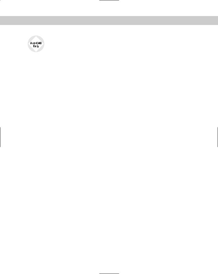
Figure 22-36 shows an example with a top view, an orthogonal view from one side, an auxiliary view, and a section.
654 Part IV Drawing in Three Dimensions
Figure 22-36: An example of using SOLVIEW.
Using SOLDRAW to create hidden lines and hatching
SOLDRAW uses the views created by SOLVIEW and creates 2D profiles that include solid and hidden lines to represent the profiles and hatching for sectional views. You must use SOLVIEW before using SOLDRAW.
To use SOLDRAW, choose Setup Drawing from the Solids toolbar. SOLDRAW puts you into a paper space layout and prompts you to select objects, which means floating view-
ports. You can select all of them if you want. SOLDRAW then proceeds to automatically create the profile views. Figure 22-37 shows an example of the hatching created for a sectional view.
Figure 22-37: The result of using SOLDRAW on a sectional view.
SOLDRAW uses hatch pattern defaults to define the hatch. You may have to change these settings using HATCHEDIT.
Note SOLVIEW creates a whole set of new layers in your drawing. SOLDRAW freezes your original layers, leaving visible only the layers needed to display the profile in that paper space viewport. SOLVIEW creates a special layer that you can use for dimensioning — one for each view that you create. For a view named front, the layer is named front-dim. You can use these dimensioning layers to create dimensions in paper space.
Using SOLPROF to create profiles
The SOLPROF command creates profiles like SOLDRAW, but you don’t need to use SOLVIEW first. In addition, SOLPROF is more interactive than SOLDRAW. To start the com-
mand, choose Setup Profile from the Solids toolbar. SOLPROF prompts you to select objects.
Chapter 22 Viewing 3D Drawings 655
Note When you start SOLPROF, you must have already created a floating viewport, and you must be in model space.
At the Display hidden profile lines on separate layer? [Yes/No] <Y>: prompt, type Y or N. By specifying Yes, you give yourself the capability of freezing or turning off the layer containing hidden parts of the model. You can also hide other 3D objects behind the one you’re profiling.
At the Project profile lines onto a plane? [Yes/No] <Y>: prompt, type Y or N. If you choose Yes, SOLPROF creates 2D objects. If you choose No, SOLPROF creates 3D objects.
At the Delete tangential edges? [Yes/No] <Y>: prompt, type Y or N. A tangential edge is the meeting of two contiguous faces. Most drafting applications don’t require you to show tangential edges.
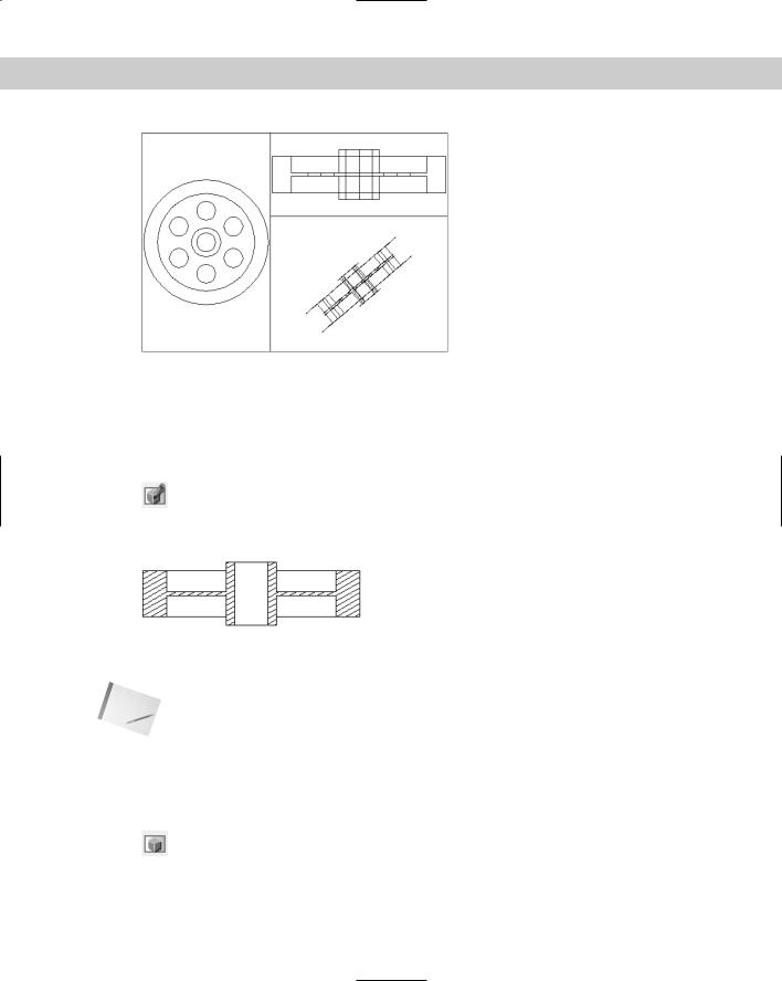
Figure 22-38 shows the result of SOLPROF after freezing the layer containing the original object — SOLPROF creates its own layers for the profile.
Figure 22-38: A profile created with SOLPROF.
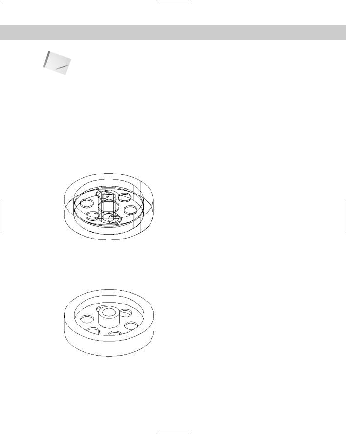
Figure 22-39 shows the result of SOLPROF after also freezing the layer that SOLPROF created containing the hidden parts of the model. In this case, the layer was named PH-159. Look for the H, which stands for hidden. The last part of the layer name is the handle of the object you’re profiling and so differs for each object.
Figure 22-39: A profile created with SOLPROF after freezing the layer containing the hidden parts of the model.
You can combine viewports created with SOLPROF and viewports created with SOLVIEW and SOLDRAW. For example, you can create two orthogonal views with SOLVIEW and SOLDRAW and then add a viewport and use SOLPROF to create another view.