

- •Foreword
- •Preface
- •Is This Book for You?
- •How This Book Is Organized
- •How to Use This Book
- •Doing the Exercises
- •Conventions Used in This Book
- •What the Icons Mean
- •About the CD-ROM
- •Other Information
- •Contacting the Author
- •Acknowledgments
- •Contents at a Glance
- •Contents
- •Getting Acquainted with AutoCAD and AutoCAD LT
- •Starting AutoCAD and AutoCAD LT
- •Creating a New Drawing
- •Using the AutoCAD and AutoCAD LT Interface
- •Creating Your First Drawing
- •Saving a Drawing
- •Summary
- •Creating a New Drawing from a Template
- •Working with Templates
- •Opening a Drawing with Default Settings
- •Opening an Existing Drawing
- •Using an Existing Drawing as a Prototype
- •Saving a Drawing Under a New Name
- •Summary
- •The Command Line
- •Command Techniques
- •Of Mice and Pucks
- •Getting Help
- •Summary
- •Typing Coordinates
- •Displaying Coordinates
- •Picking Coordinates on the Screen
- •Locating Points
- •Summary
- •Unit Types
- •Drawing Limits
- •Understanding Scales
- •Inserting a Title Block
- •Common Setup Options
- •The MVSETUP Command
- •Summary
- •Using the LINE Command
- •Drawing Rectangles
- •Drawing Polygons
- •Creating Construction Lines
- •Creating Rays
- •Summary
- •Drawing Circles
- •Drawing Arcs
- •Creating Ellipses and Elliptical Arcs
- •Making Donuts
- •Placing Points
- •Summary
- •Panning
- •The ZOOM Command
- •Aerial View
- •Named Views
- •Tiled Viewports
- •Snap Rotation
- •User Coordinate Systems
- •Isometric Drawing
- •Summary
- •Editing a Drawing
- •Selecting Objects
- •Summary
- •Copying and Moving Objects
- •Using Construction Commands
- •Creating a Revision Cloud
- •Hiding Objects with a Wipeout
- •Double-Clicking to Edit Objects
- •Grips
- •Editing with the Properties Palette
- •Selection Filters
- •Groups
- •Summary
- •Working with Layers
- •Changing Object Color, Linetype, and Lineweight
- •Working with Linetype Scales
- •Importing Layers and Linetypes from Other Drawings
- •Matching Properties
- •Summary
- •Drawing-Level Information
- •Object-Level Information
- •Measurement Commands
- •AutoCAD’s Calculator
- •Summary
- •Creating Single-Line Text
- •Understanding Text Styles
- •Creating Multiline Text
- •Creating Tables
- •Inserting Fields
- •Managing Text
- •Finding Text in Your Drawing
- •Checking Your Spelling
- •Summary
- •Working with Dimensions
- •Drawing Linear Dimensions
- •Drawing Aligned Dimensions
- •Creating Baseline and Continued Dimensions
- •Dimensioning Arcs and Circles
- •Dimensioning Angles
- •Creating Ordinate Dimensions
- •Drawing Leaders
- •Using Quick Dimension
- •Editing Dimensions
- •Summary
- •Understanding Dimension Styles
- •Defining a New Dimension Style
- •Changing Dimension Styles
- •Creating Geometric Tolerances
- •Summary
- •Creating and Editing Polylines
- •Drawing and Editing Splines
- •Creating Regions
- •Creating Boundaries
- •Creating Hatches
- •Creating and Editing Multilines
- •Creating Dlines
- •Using the SKETCH Command
- •Digitizing Drawings with the TABLET Command
- •Summary
- •Preparing a Drawing for Plotting or Printing
- •Creating a Layout in Paper Space
- •Working with Plot Styles
- •Plotting a Drawing
- •Summary
- •Combining Objects into Blocks
- •Inserting Blocks and Files into Drawings
- •Managing Blocks
- •Using Windows Features
- •Working with Attributes
- •Summary
- •Understanding External References
- •Editing an Xref within Your Drawing
- •Controlling Xref Display
- •Managing Xrefs
- •Summary
- •Preparing for Database Connectivity
- •Connecting to Your Database
- •Linking Data to Drawing Objects
- •Creating Labels
- •Querying with the Query Editor
- •Working with Query Files
- •Summary
- •Working with 3D Coordinates
- •Using Elevation and Thickness
- •Working with the User Coordinate System
- •Summary
- •Working with the Standard Viewpoints
- •Using DDVPOINT
- •Working with the Tripod and Compass
- •Getting a Quick Plan View
- •Shading Your Drawing
- •Using 3D Orbit
- •Using Tiled Viewports
- •Defining a Perspective View
- •Laying Out 3D Drawings
- •Summary
- •Drawing Surfaces with 3DFACE
- •Drawing Surfaces with PFACE
- •Creating Polygon Meshes with 3DMESH
- •Drawing Standard 3D Shapes
- •Drawing a Revolved Surface
- •Drawing an Extruded Surface
- •Drawing Ruled Surfaces
- •Drawing Edge Surfaces
- •Summary
- •Drawing Standard Shapes
- •Creating Extruded Solids
- •Drawing Revolved Solids
- •Creating Complex Solids
- •Sectioning and Slicing Solids
- •Using Editing Commands in 3D
- •Editing Solids
- •Listing Solid Properties
- •Summary
- •Understanding Rendering
- •Creating Lights
- •Creating Scenes
- •Working with Materials
- •Using Backgrounds
- •Doing the Final Render
- •Summary
- •Accessing Drawing Components with the DesignCenter
- •Accessing Drawing Content with Tool Palettes
- •Setting Standards for Drawings
- •Organizing Your Drawings
- •Working with Sheet Sets
- •Maintaining Security
- •Keeping Track of Referenced Files
- •Handling Errors and Crashes
- •Managing Drawings from Prior Releases
- •Summary
- •Importing and Exporting Other File Formats
- •Working with Raster Images
- •Pasting, Linking, and Embedding Objects
- •Summary
- •Sending Drawings
- •Opening Drawings from the Web
- •Creating Object Hyperlinks
- •Publishing Drawings
- •Summary
- •Working with Customizable Files
- •Creating Keyboard Shortcuts for Commands
- •Customizing Toolbars
- •Customizing Tool Palettes
- •Summary
- •Creating Macros with Script Files
- •Creating Slide Shows
- •Creating Slide Libraries
- •Summary
- •Creating Linetypes
- •Creating Hatch Patterns
- •Summary
- •Creating Shapes
- •Creating Fonts
- •Summary
- •Working with Menu Files
- •Customizing a Menu
- •Summary
- •Introducing Visual LISP
- •Getting Help in Visual LISP
- •Working with AutoLISP Expressions
- •Using AutoLISP on the Command Line
- •Creating AutoLISP Files
- •Summary
- •Creating Variables
- •Working with AutoCAD Commands
- •Working with Lists
- •Setting Conditions
- •Managing Drawing Objects
- •Getting Input from the User
- •Putting on the Finishing Touches
- •Summary
- •Understanding Local and Global Variables
- •Working with Visual LISP ActiveX Functions
- •Debugging Code
- •Summary
- •Starting to Work with VBA
- •Writing VBA Code
- •Getting User Input
- •Creating Dialog Boxes
- •Modifying Objects
- •Debugging and Trapping Errors
- •Moving to Advanced Programming
- •A Final Word
- •Installing AutoCAD and AutoCAD LT
- •Configuring AutoCAD
- •Starting AutoCAD Your Way
- •Configuring a Plotter
- •System Requirements
- •Using the CD with Microsoft Windows
- •What’s on the CD
- •Troubleshooting
- •Index

Getting Information from Your Drawing
Your drawing is intelligent in many ways. Several commands can give you the details of each object. In addition, you can get list-
ings that provide information about your drawing as a whole. I’ve mentioned system variables previously in this book — you can list system variables and their current settings.
You can perform calculations on objects that may assist you in certain drawing tasks. For example, you can divide an object into any number of segments by placing point objects along the object, or you can place point objects at a specified distance along the object. You can use AutoCAD’s calculator, which not only does regular numerical calculations but also works with coordinates and geometric points on objects.
Drawing-Level Information
Some information applies to the drawing as a whole or even to your computer system as a whole, rather than to individual objects. This information can be important when there is a problem or when you simply need to find the status of system variables.
Listing the status of your drawing
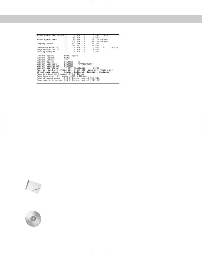
The STATUS command is only available in AutoCAD and provides a standard list of information that can be very helpful. To use the STATUS command, choose Tools Inquiry Status. Figure 12-1 shows a sample status listing.
The command lists the number of objects in your drawing, and then the limits and extents of the drawing, as well as the extents of the current display on your screen. Other items are the snap and grid spacing as well as the current layer, color, linetype, and lineweight. You can see that Fill is on but the other drawing aid settings are off. Center, endpoint, midpoint, and quadrant running object snaps are on. Finally, information also appears about free disk space and free memory.
12C H A P T E R
In This Chapter
Getting drawing-wide information
Getting information about objects
Measuring and segmenting objects
Using AutoCAD’s calculator
276 Part II Drawing in Two Dimensions
Figure 12-1: A sample listing from the STATUS command.
Obviously, much of this information is available without using the STATUS command. The easiest items to find are the current layer, color, linetype, and lineweight, which are readily visible on the Layers and Properties toolbars. However, you would have to use a number of commands to obtain other information such as the snap and grid spacing and the drawing limits. STATUS puts it all together in one listing. Finally, the free disk and memory statistics provide valuable information not otherwise obtainable from within your drawing.
The most common use for STATUS is to troubleshoot problems. You could send the listing to a colleague in another office who needs to work on the same drawing. Your colleague can then work more easily by using the same settings you have used.
Listing system variables
In Chapter 5, I explained that AutoCAD and AutoCAD LT store settings in system variables. In the previous chapter, for example, I mentioned that the global linetype scale is stored in the LTSCALE system variable, and the object linetype scale is stored in the CELTSCALE system variable. You may want to know the settings of a group of related system variables. The SETVAR command provides a listing of all the system variables and their settings. It may be quicker to view system-variable settings by using the SETVAR command than typing each individual system variable on the command line.
Too many system variables exist to show the entire listing here, but a few can convey the wealth of information available, as shown in Figure 12-2.
Note Read-only system variables are for information only and cannot be changed. An example is LOGINNAME, which shows the current user’s name registered on the system. Other system variables can be changed.
Although some system variables allow any or a variety of values, many are either on or off. In general, a setting of 1 means on and 0 means off.
On the |
Bonus Chapter 1 lists useful, new, changed, and deleted system variables, including a brief |
CD-ROM |
explanation of each. |
|
Most system variables do not need to be set directly. In Chapter 11, for example, you set the LTSCALE system variable by using the Linetype Manager. However, a few system variables can be accessed only by typing them on the command line.

Chapter 12 Getting Information from Your Drawing |
277 |
Figure 12-2: A partial SETVAR listing.
You can use SETVAR to set system variables (that are not read-only) as well as to list them. To list the system variables, choose Tools Inquiry Set Variable. If you are using AutoCAD LT, it can be accessed only at the command line by typing SETVAR. At the Enter variable name or [?]: prompt, type ? . At the Enter variable(s) to list <*>: prompt, press Enter to list all the system variables or type the name of a variable. (You can use the * and ? wildcards in the name.) The command either lists all the system variables or just the variable you typed.
If you type a variable, the command prompts you for a new value so that you can change it. For example, if you type celtscale, you see the Enter new value for CELTSCALE <1.0000>: prompt. You can then change the system variable by typing in a new value. You can simply press Enter to accept the current setting.
Tracking drawing time
You can track the time you spend working on a drawing. This feature is most often used for billing time to clients, or maybe your boss wants to see how much you’re getting done.
Cross- |
Chapter 26 explains how to keep a log file of your drawing activity. |
Reference |
|
To use the TIME command, choose Tools Inquiry Time. A typical listing is shown in Figure 12-3.
Figure 12-3: A typical TIME listing.
Table 12-1 shows the meaning of the listing that you get from the TIME command.
278 Part II Drawing in Two Dimensions
|
Table 12-1: TIME Command Information |
|
|
Listing |
Comments |
|
|
Current time |
The current date and time. The time is displayed to the nearest millisecond. |
Created |
The date and time the drawing was created. |
Last updated |
The date and time of the last save of the drawing. |
Total editing time |
Accumulates the time spent in the drawing from session to session, not |
|
including plotting time or time you worked on the drawing and quit without |
|
saving your changes. |
Elapsed timer |
Also accumulates time spent in the drawing, but you can turn this on and off |
|
and reset it. |
Next automatic save in |
Shows when your drawing will automatically be saved. Choose Tools |
|
Options and click the Open and Save tab to set how often you want to |
|
automatically save your drawing. |
|
|
You can think of total editing time as your car’s odometer and elapsed time as a timer (like the trip meter that some cars have that lets you time a specific trip).
At the end of the listing, you see the Enter option [Display/ON/OFF/Reset]: prompt. The Display option redisplays the listing with updated times. ON and OFF turn the elapsed time on and off. The Reset option resets the elapsed time to zero.
On the
CD-ROM
The Express Tools contain a new tool, EDITTIME (choose Express Tools Dwg Edit Time) that tracks active editing time.
The drawing used in the following Step-by-Step exercise on obtaining drawing information, ab12-a.dwg, is in the Drawings folder on the CD-ROM.
STEP-BY-STEP: Obtaining Drawing Information
1.Open ab12-a.dwg from the CD-ROM.
2.Skip to Step 3 if you are using AutoCAD LT. Choose Tools Inquiry Status. Look at the listing to see how many objects it contains. Check the limits of the drawing. Look at the grid spacing. Read through any other items of interest to you.
3.Choose Tools Inquiry Set Variable, or type in SETVAR at the command line if you are using AutoCAD LT. At the Enter variable name or [?]: prompt, type ? . At the Enter variable(s) to list <*>: prompt, press Enter to accept the default. Look for the BLIPMODE setting. Check the location of the drawing (DWGPREFIX). Look for the global linetype scale (LTSCALE). Press Enter until you see the Command: prompt again.
4.Press Enter to start the SETVAR command again. At the Enter variable name or [?]: prompt, type ltscale . Type 50 to change the linetype scale. Type regen . (Notice that the noncontinuous linetypes now show up more clearly.)