

- •Foreword
- •Preface
- •Is This Book for You?
- •How This Book Is Organized
- •How to Use This Book
- •Doing the Exercises
- •Conventions Used in This Book
- •What the Icons Mean
- •About the CD-ROM
- •Other Information
- •Contacting the Author
- •Acknowledgments
- •Contents at a Glance
- •Contents
- •Getting Acquainted with AutoCAD and AutoCAD LT
- •Starting AutoCAD and AutoCAD LT
- •Creating a New Drawing
- •Using the AutoCAD and AutoCAD LT Interface
- •Creating Your First Drawing
- •Saving a Drawing
- •Summary
- •Creating a New Drawing from a Template
- •Working with Templates
- •Opening a Drawing with Default Settings
- •Opening an Existing Drawing
- •Using an Existing Drawing as a Prototype
- •Saving a Drawing Under a New Name
- •Summary
- •The Command Line
- •Command Techniques
- •Of Mice and Pucks
- •Getting Help
- •Summary
- •Typing Coordinates
- •Displaying Coordinates
- •Picking Coordinates on the Screen
- •Locating Points
- •Summary
- •Unit Types
- •Drawing Limits
- •Understanding Scales
- •Inserting a Title Block
- •Common Setup Options
- •The MVSETUP Command
- •Summary
- •Using the LINE Command
- •Drawing Rectangles
- •Drawing Polygons
- •Creating Construction Lines
- •Creating Rays
- •Summary
- •Drawing Circles
- •Drawing Arcs
- •Creating Ellipses and Elliptical Arcs
- •Making Donuts
- •Placing Points
- •Summary
- •Panning
- •The ZOOM Command
- •Aerial View
- •Named Views
- •Tiled Viewports
- •Snap Rotation
- •User Coordinate Systems
- •Isometric Drawing
- •Summary
- •Editing a Drawing
- •Selecting Objects
- •Summary
- •Copying and Moving Objects
- •Using Construction Commands
- •Creating a Revision Cloud
- •Hiding Objects with a Wipeout
- •Double-Clicking to Edit Objects
- •Grips
- •Editing with the Properties Palette
- •Selection Filters
- •Groups
- •Summary
- •Working with Layers
- •Changing Object Color, Linetype, and Lineweight
- •Working with Linetype Scales
- •Importing Layers and Linetypes from Other Drawings
- •Matching Properties
- •Summary
- •Drawing-Level Information
- •Object-Level Information
- •Measurement Commands
- •AutoCAD’s Calculator
- •Summary
- •Creating Single-Line Text
- •Understanding Text Styles
- •Creating Multiline Text
- •Creating Tables
- •Inserting Fields
- •Managing Text
- •Finding Text in Your Drawing
- •Checking Your Spelling
- •Summary
- •Working with Dimensions
- •Drawing Linear Dimensions
- •Drawing Aligned Dimensions
- •Creating Baseline and Continued Dimensions
- •Dimensioning Arcs and Circles
- •Dimensioning Angles
- •Creating Ordinate Dimensions
- •Drawing Leaders
- •Using Quick Dimension
- •Editing Dimensions
- •Summary
- •Understanding Dimension Styles
- •Defining a New Dimension Style
- •Changing Dimension Styles
- •Creating Geometric Tolerances
- •Summary
- •Creating and Editing Polylines
- •Drawing and Editing Splines
- •Creating Regions
- •Creating Boundaries
- •Creating Hatches
- •Creating and Editing Multilines
- •Creating Dlines
- •Using the SKETCH Command
- •Digitizing Drawings with the TABLET Command
- •Summary
- •Preparing a Drawing for Plotting or Printing
- •Creating a Layout in Paper Space
- •Working with Plot Styles
- •Plotting a Drawing
- •Summary
- •Combining Objects into Blocks
- •Inserting Blocks and Files into Drawings
- •Managing Blocks
- •Using Windows Features
- •Working with Attributes
- •Summary
- •Understanding External References
- •Editing an Xref within Your Drawing
- •Controlling Xref Display
- •Managing Xrefs
- •Summary
- •Preparing for Database Connectivity
- •Connecting to Your Database
- •Linking Data to Drawing Objects
- •Creating Labels
- •Querying with the Query Editor
- •Working with Query Files
- •Summary
- •Working with 3D Coordinates
- •Using Elevation and Thickness
- •Working with the User Coordinate System
- •Summary
- •Working with the Standard Viewpoints
- •Using DDVPOINT
- •Working with the Tripod and Compass
- •Getting a Quick Plan View
- •Shading Your Drawing
- •Using 3D Orbit
- •Using Tiled Viewports
- •Defining a Perspective View
- •Laying Out 3D Drawings
- •Summary
- •Drawing Surfaces with 3DFACE
- •Drawing Surfaces with PFACE
- •Creating Polygon Meshes with 3DMESH
- •Drawing Standard 3D Shapes
- •Drawing a Revolved Surface
- •Drawing an Extruded Surface
- •Drawing Ruled Surfaces
- •Drawing Edge Surfaces
- •Summary
- •Drawing Standard Shapes
- •Creating Extruded Solids
- •Drawing Revolved Solids
- •Creating Complex Solids
- •Sectioning and Slicing Solids
- •Using Editing Commands in 3D
- •Editing Solids
- •Listing Solid Properties
- •Summary
- •Understanding Rendering
- •Creating Lights
- •Creating Scenes
- •Working with Materials
- •Using Backgrounds
- •Doing the Final Render
- •Summary
- •Accessing Drawing Components with the DesignCenter
- •Accessing Drawing Content with Tool Palettes
- •Setting Standards for Drawings
- •Organizing Your Drawings
- •Working with Sheet Sets
- •Maintaining Security
- •Keeping Track of Referenced Files
- •Handling Errors and Crashes
- •Managing Drawings from Prior Releases
- •Summary
- •Importing and Exporting Other File Formats
- •Working with Raster Images
- •Pasting, Linking, and Embedding Objects
- •Summary
- •Sending Drawings
- •Opening Drawings from the Web
- •Creating Object Hyperlinks
- •Publishing Drawings
- •Summary
- •Working with Customizable Files
- •Creating Keyboard Shortcuts for Commands
- •Customizing Toolbars
- •Customizing Tool Palettes
- •Summary
- •Creating Macros with Script Files
- •Creating Slide Shows
- •Creating Slide Libraries
- •Summary
- •Creating Linetypes
- •Creating Hatch Patterns
- •Summary
- •Creating Shapes
- •Creating Fonts
- •Summary
- •Working with Menu Files
- •Customizing a Menu
- •Summary
- •Introducing Visual LISP
- •Getting Help in Visual LISP
- •Working with AutoLISP Expressions
- •Using AutoLISP on the Command Line
- •Creating AutoLISP Files
- •Summary
- •Creating Variables
- •Working with AutoCAD Commands
- •Working with Lists
- •Setting Conditions
- •Managing Drawing Objects
- •Getting Input from the User
- •Putting on the Finishing Touches
- •Summary
- •Understanding Local and Global Variables
- •Working with Visual LISP ActiveX Functions
- •Debugging Code
- •Summary
- •Starting to Work with VBA
- •Writing VBA Code
- •Getting User Input
- •Creating Dialog Boxes
- •Modifying Objects
- •Debugging and Trapping Errors
- •Moving to Advanced Programming
- •A Final Word
- •Installing AutoCAD and AutoCAD LT
- •Configuring AutoCAD
- •Starting AutoCAD Your Way
- •Configuring a Plotter
- •System Requirements
- •Using the CD with Microsoft Windows
- •What’s on the CD
- •Troubleshooting
- •Index

Chapter 22 Viewing 3D Drawings 633
STEP-BY-STEP: Shading a Drawing
1.Open ab22-b.dwg from the CD-ROM.
2.Save it as ab22-02.dwg in your AutoCAD Bible folder.
3.Choose Tools Options and choose the System tab.
4.In Current 3D Graphics Display, choose your graphics system (it’s probably already selected) and click Properties.
5.Check Render Options and then click Enable Materials. (If you’re not using the default Heidi graphics display system, your options may be different.)
6.Click Apply & Close. Click OK to close the Options dialog box.
7.Choose View Shade Flat Shaded. This model has a brass-like material attached to it.
8.Choose View Shade Gouraud Shaded.
9.Choose View Shade Gouraud Shaded, Edges On.
10.Save your drawing. It should look like Figure 22-20.
Figure 22-20: The model shaded with the Gouraud
Shaded, Edges On option.
Using 3D Orbit
3D orbit enables you to view a 3D model by freely changing your view in real-time. Using 3D orbit is like orbiting the earth to view any continent or ocean below. When you enter 3D orbit mode, you cannot use other commands. In this regard, 3D orbit is like Realtime Pan and Realtime Zoom. Similarly, you press Esc or Enter to exit 3D orbit mode.
Because you cannot use other commands while in 3D orbit, you access the 3D orbit options by right-clicking in the drawing area to display the 3D Orbit shortcut menu. You might find the 3D Orbit toolbar helpful when working with 3D orbit. The toolbar contains many of the options available on the 3D Orbit shortcut menu. Right-click any toolbar and choose 3D Orbit to display the toolbar.
634 Part IV Drawing in Three Dimensions
Tip 3D orbit can be used as a substitute for DVIEW, which is covered later in this chapter.
|
Starting 3D orbit |
|
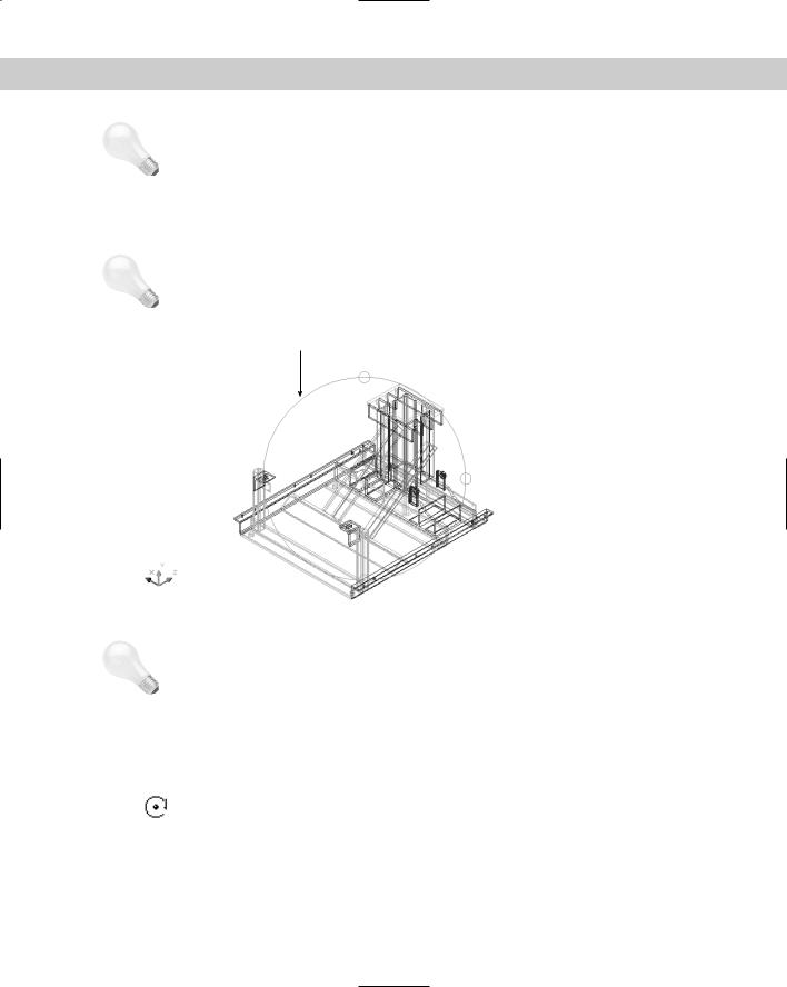
To start 3D orbit, choose View 3D Orbit. You enter 3D orbit mode and displays the arcball |
|
around the objects in your view, as shown in Figure 22-21. |
Tip |
You can use 3D orbit transparently, that is, in the middle of another command. Just start a |
|
command, type '3dorbit , rotate your model as you want, and press Esc or Enter to close |
|
3D orbit. You then continue the command in progress. |
|
Arcball |
|
Figure 22-21: 3D orbit mode. |
Tip |
For faster performance, select only the objects you want to view with 3D orbit before starting |
|
the command. Objects you did not select disappear while you’re in 3D orbit mode. Of |
|
course, they reappear as soon as you leave 3D orbit mode. |
|
3D orbit has four cursors that affect how your model rotates. Each cursor is location-based. |
|
As you move your cursor to a new location, the cursor shape automatically changes and the |
|
type of rotation changes. |
|
Rolling with the circular arrow cursor |
|
When you place your cursor outside the arcball, it takes the shape of a circular arrow. |
|
As you click and drag around the outside of the arcball, your model turns around an |
|
imaginary axis that extends from the center of the arcball outward, perpendicular to the |
|
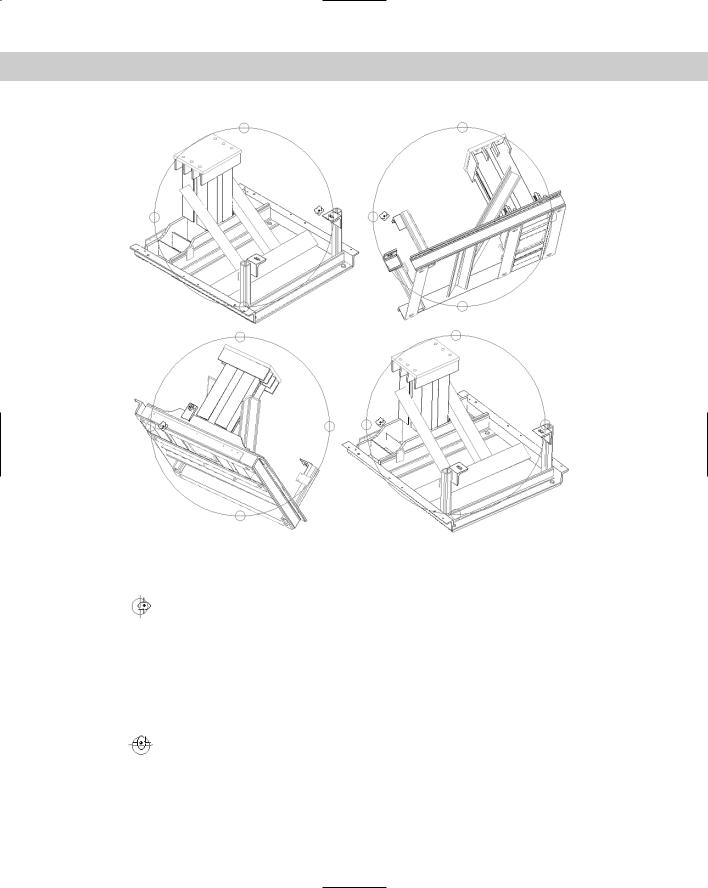
screen — that is, pointing at you. This type of rotation is called a roll. Figure 22-22 shows a |
|
model with the circular arrow cursor at 0°, 90°, 180°, and 270°. The model uses a hidden view |

Chapter 22 Viewing 3D Drawings 635
for clarity — using hidden and shaded views with 3D orbit is covered later in this chapter. After you get to the view you want, release the mouse button to redraw your model on the screen in the new position.
Rotating freely with the sphere and lines cursor
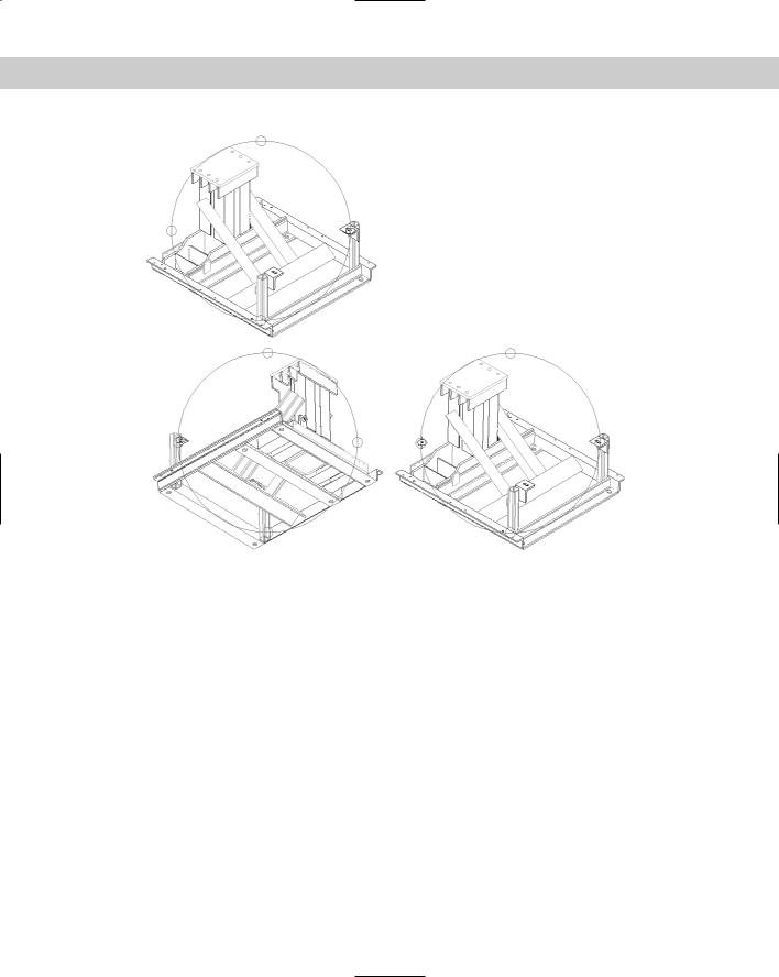
As soon as you move your cursor within the arcball, it takes a shape called “a small sphere encircled by two lines.” As you click and drag within the arcball, your model
moves around the center of the arcball in the direction you drag. Imagine that your model is encased in a transparent sphere, like one of those gerbil or hamster balls. As you drag the cursor, you’re rotating the sphere around its center point. If you drag from one edge of the arcball to its opposite edge, you can release the mouse, move back to your starting point, and then click and drag again in the same direction. When you do this a few times, you rotate your model 360 degrees. You get best results dragging in a line of any direction, rather than ’round and ’round. Figure 22-23 shows a model rotated using the sphere and lines cursor. For each pane of the figure, the cursor is dragged from just inside the right arcball circle to just inside the left arcball circle (that is, horizontally).
Figure 22-22: Using the circular arrow cursor to rotate your model around an axis.
636 Part IV Drawing in Three Dimensions
Figure 22-23: Using the sphere and lines cursor to rotate your model around its center.
Rotating around the vertical axis with the horizontal ellipse cursor
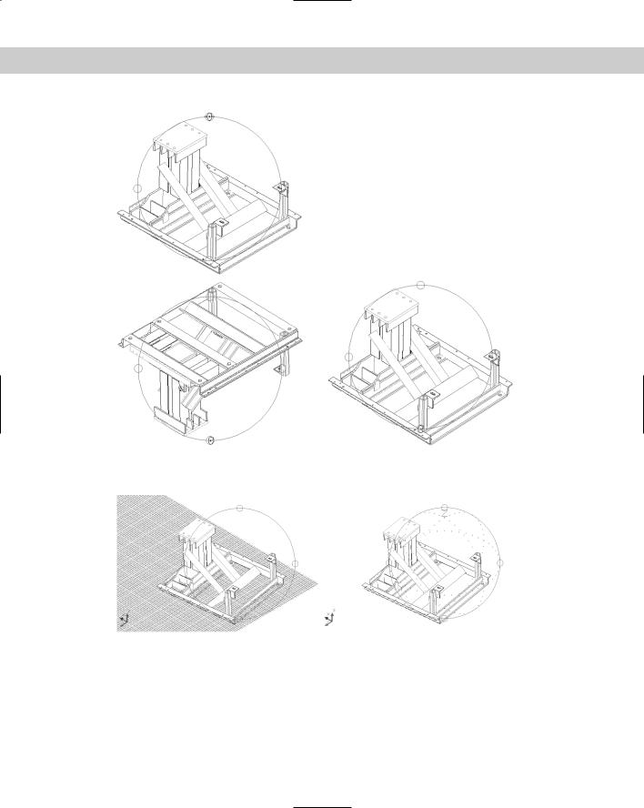
When you move your cursor over either the left or right quadrant circle on the arcball, it becomes a horizontal ellipse. As you click and drag from either quadrant, your model rotates around the arcball’s vertical axis, which extends from the top quadrant to the bottom
quadrant. Although your cursor enters the arcball, it retains its horizontal ellipse form until you release the mouse button. You can drag from one quadrant to its opposite quadrant, release the mouse button, move back to your starting point, and then click and drag again in the same direction. When you do this a couple times, you rotate your model 360 degrees. Figure 22-24 shows a model rotated using the horizontal ellipse cursor.
Rotating around the horizontal axis with the vertical ellipse cursor
When you move your cursor over either the top or bottom quadrant circle on the arcball, it becomes a vertical ellipse. As you click and drag from either quadrant, your
model rotates around the arcball’s horizontal axis, which extends from the left quadrant to the right quadrant. You can drag from one quadrant to its opposite quadrant, release the mouse button, move back to your starting point, and then click and drag again in the same direction. When you do this a couple times, you rotate your model 360 degrees. Figure 22-25 shows a model rotated using the vertical ellipse cursor.
Chapter 22 Viewing 3D Drawings 637
Figure 22-24: Using the horizontal ellipse cursor to rotate your model around the arcball’s vertical axis.
Using the 3D orbit visual aids
3D orbit includes three visual aids that can help you get your bearings:
Compass: Displays a sphere within the arcball made up of three dashed lines labeled as the X, Y, and Z axes. The lines make your arcball look like a baseball. To display the compass, right-click and choose Visual Aids Compass from the shortcut menu.
Grid: Displays a grid of lines representing the XY plane. The Z coordinate of the grid is equal to the value of the ELEVATION system variable, which is set to 0 (zero) by default. Up to ten horizontal and vertical lines are drawn between the major lines, whose distance from each other is equal to the value of the GRIDUNIT system variable. You can set this value by choosing Tools Drafting Settings before you use this visual aid.
3D UCS icon: Displays the 3D UCS icon, a shaded, three-dimensional UCS icon. The X axis is red, the Y axis is green, and the Z axis is blue.
Figure 22-26 shows a model with the grid and one with the compass. Both display the 3D UCS icon. You would rarely want to use all three. The compass and grid can both interfere with viewing your model and should be used temporarily when needed.
638 Part IV Drawing in Three Dimensions
Figure 22-25: Using the vertical ellipse cursor to rotate your model around the arcball’s horizontal axis.
Figure 22-26: 3D orbit’s visual aids — the 3D UCS icon, the grid, and the compass.
To display the visual aids, right-click while in 3D orbit mode and choose Visual Aids from the shortcut menu. Then choose the aid you want from the submenu. To turn off the visual aids, follow the same procedure — the submenu items toggle the visual aids on and off when you click them.

Chapter 22 Viewing 3D Drawings 639
Note |
If you choose a shading mode (other than the default 2D wireframe), the visual aids remain |
|
active after you exit 3D orbit. You can switch to 2D wireframe shading mode, as explained |
|
earlier in this chapter, or you can re-enter 3D orbit and turn off the visual aids. |
Creating a continuous orbit
Absolutely the coolest feature of 3D orbit — and one of the coolest features of AutoCAD as a whole — is continuous orbit. Continuous orbit enables you to choose a direction of rotation and let go. 3D orbit automatically continues the rotation in the same direction and continues it until you change or stop it. With continuous orbit, who needs screensavers any more? Here’s how it works:
1.With 3D orbit active, right-click and choose More Continuous Orbit.
2.Click and drag in the direction of rotation that you want to create.
3.Release your mouse button. Your model continues to rotate in the same direction. All you do is watch.
Continuous orbit is an ideal way to view your model. As your model rotates, you can pick out any errors and stop continuous orbit then. You can change the direction of your continuous orbit at any time by clicking and dragging in a new direction and then releasing the mouse button.
To stop continuous orbit, choose Pan, Zoom, or Orbit from the shortcut menu. Zoom Previous exits 3D orbit and restores the view to the way it was before the orbit began.
Resetting the view
You can end up with some strange views of your model with 3D orbit. With that in mind, AutoCAD provides a way to reset your view to the view that was current when you first started 3D orbit. With 3D orbit active, right-click and choose Reset View from the shortcut menu.
Refining your 3D orbit view
3D orbit offers many options for refining your view so that you get just the view you want. You can pan and zoom, adjust the camera distance, change the camera and target locations, create parallel and perspective views, set clipping planes, use a preset view, use shading options, and use materials that you’ve attached to objects. (See Chapter 25 for more about materials.)
Because you cannot use other commands while in 3D orbit mode, you access most of these options by right-clicking in the drawing area to access the 3D Orbit shortcut menu. You can also use the 3D Orbit toolbar for some of these options.
Panning in 3D orbit
To pan in 3D orbit, right-click and choose Pan from the 3D orbit shortcut menu. You see the familiar hand cursor. Click and drag to pan, in the same way you normally pan in real-time. To stop panning, right-click and choose Orbit or Zoom from the shortcut menu.
You can pan with visual aids, shading modes, and projection options active.
640 Part IV Drawing in Three Dimensions
Zooming in 3D orbit
To zoom in 3D orbit, right-click and choose Zoom from the 3D orbit shortcut menu. You see the familiar magnifying glass cursor with a plus (+) and a minus (–) sign. Click and drag in the direction of the plus sign (toward the top of your screen) to zoom in; click and drag in the direction of the minus sign (toward the bottom of your screen) to zoom out, just as you do when you normally use zoom real-time. To stop zooming, right-click and choose Orbit or Pan from the shortcut menu. You can zoom with visual aids, shading modes, and projection options active.
Zooming to a window and to extents in 3D orbit
To zoom to a window in 3D orbit, right-click and choose More Zoom Window from the shortcut menu. Your cursor displays a small rectangle. Click and drag, and then release the mouse button to define the two corners of the window.
To zoom to drawing extents in 3D orbit, right-click and choose More Zoom Extents from the shortcut menu.
Keeping the Z axis orientation steady
Controlling the orbiting with 3D orbit can be difficult. You may find that as you drag horizontally in the arcball, your model tumbles upside down. Orbit Maintains Z keeps the Z axis in its current direction when you drag horizontally within the arcball or horizontally from the left or right ellipse of the arcball. Use this option to prevent your object from rolling around. The idea is that you don’t want to see certain objects, such as houses, upside down.
To turn on this feature, right-click in 3D orbit and choose More Orbit Maintains Z. Repeat the process to turn off the feature — it’s a toggle. AutoCAD saves this setting in your user profile so that it carries over to other drawings.
Adjusting the camera distance
You can adjust the distance between the viewer, called the camera, and the target, which by default is set to the center of the 3D view (which may be different from the center of your model). Changing this camera distance is equivalent to zooming in and out.
To adjust the camera distance in 3D orbit, right-click and choose More Adjust Distance from the shortcut menu. The cursor changes to a horizontal line with a double-headed arrow pointing up and down. Click and drag toward the top of your screen to move the camera closer to your objects — similar to zooming in. Click and drag toward the bottom of your screen to move the camera away from your objects — similar to zooming out.
Changing the camera and target locations
You may also want to change the focus of your view. 3D orbit uses a default focus that is the center of the 3D view. You can change both the camera and target locations, but you must do so before you start 3D orbit.
To change the camera and the target locations, type camera on the command line.
At the Specify new camera position <-41.0494,129.5726,56.6437>: prompt, use any method to specify new coordinates for the camera position. The numbers in the brackets are the current settings. At the Specify new camera target <20.8937,67.6295,-5.2993>: prompt, use any method to specify new coordinates for the target position.

Chapter 22 Viewing 3D Drawings 641
Tip |
Specifying the proper coordinates can be difficult in 3D. You may find it helpful to place a |
|
point object at the two desired locations before starting the command. You can then use the |
|
Node object snap to pick the camera and target positions you want. |
Controlling view width and height
When you use 3D orbit, the Properties palette displays special properties that relate to 3D orbit features.
View Height is a way to specify the distance of the imaginary camera. In other words, you can use this property to zoom in and out on your model. A larger number makes your model look smaller because the distance (or height) of the camera from the model increases.
View Width is another way to zoom in and out. Here you specify the width of the view of the imaginary camera. A larger number makes your model look smaller because the view encompasses a larger area (and your model is a smaller part of that area).
To change these properties, click their row in the Properties palette. Type a new value and press Enter.
Creating parallel and perspective views
By default, 3D orbit (and all three-dimensional viewpoints) displays a parallel view. In a parallel view, parallel lines never converge. The value of a parallel view is that the shapes in your drawing do not appear distorted as you zoom in. In a perspective view, parallel lines converge. You may have had an assignment in art class (long ago) to draw railroad tracks that converge to give the impression of distance. Perspective view is more realistic because railroad tracks really do seem to converge in the distance. However, when you zoom in, these objects appear distorted. Use a perspective view when you want to convey a realistic sense of depth. In general, perspective view is most useful in architectural settings.
To create a perspective view in 3D orbit, right-click and choose Projection Perspective. To return to parallel view, choose Projection Parallel. For more information on perspective views, see the section “Defining a Perspective View” later in this chapter.
Caution |
If you leave 3D orbit in perspective view, you cannot edit, pick points, zoom, or pan. To return |
|
to your normal parallel view, re-enter 3D orbit, right-click, and choose Projection Parallel. |
|
Then exit 3D orbit again. |
Using a preset view
After using 3D orbit a few times, you might find your model all askew, with no idea how to get it back to a viewpoint you can comprehend. You can switch to any of the preset views discussed at the beginning of this chapter. From 3D orbit, right-click and choose Preset Views from the shortcut menu. Then choose one of the standard viewpoints on the submenu list.
Setting clipping planes
You can create two invisible planes, a front clipping plane and a back clipping plane, that block your view of any objects outside the planes. Setting clipping planes is a good way to discard objects that you don’t want to see because they’re too close or too far away. For example, you might have a 3D house with trees in the background and a street sign in the foreground. Using clipping planes, you can block out the view of the trees and the street sign and view only the house.

642 Part IV Drawing in Three Dimensions
The Adjust Clipping Planes window enables you to visually move the front and back clipping planes in real-time and immediately see the results.
Because the clipping planes are parallel to your screen, you need to start by creating a view that is straight enough so that your clipping planes will cut across your model at the desired angle. I suggest using one of the preset views, as I just previously explained. For example, if you’re looking at a house and want to clip off the front and back porches, use the Front preset view to view your house from the front. You will then be able to create the desired front and back clipping planes. After you set your view, follow these steps:
1.From 3D orbit, right-click and choose More Adjust Clipping Planes. AutoCAD displays the Adjust Clipping Planes window, shown in Figure 22-27.
2.In the Adjust Clipping Planes window you can do the following:
•Adjust Front Clipping: Click this button on the toolbar to move the front clipping plane. Use the Adjust Clipping Planes cursor to click and drag the
line that represents the front clipping plane.
•Adjust Back Clipping: Click this button on the toolbar to move the back
clipping plane. Use the Adjust Clipping Planes cursor to click and drag the line that represents the back clipping plane.
•Create Slice: After you adjust both the front and back clipping planes, use this button to move both clipping planes together, either up or down. Their
distance from each other remains constant.
Back clipping pane
Adjust Clipping Planes toolbar Front clipping plane
Figure 22-27: The Adjust Clipping Planes window, shown with the model on the drawing area.

Chapter 22 Viewing 3D Drawings 643
New |
Pan and Zoom inside the Adjust Clipping Planes window is new for AutoCAD 2005. |
Feature |
|
• Pan: Click to pan the view inside the Adjust Clipping Planes window.
• Zoom: Click to zoom the view inside the Adjust Clipping Planes window.
•Front Clipping On/Off: Click this button to toggle the front clipping plane on or off.
•Back Clipping On/Off: Click this button to toggle the back clipping plane on or off.
3.If you can’t see the back clipping plane, click Adjust Back Clipping and continue to drag down until the line representing the back clipping plane appears. If you can’t see the front clipping plane, click Adjust Front Clipping and continue to drag up until the line representing the front clipping plane appears.
4.After you set the clipping planes to your satisfaction, click the window’s Close box. You can now rotate you model in any direction and 3D orbit continually hides any portion of the model outside the clipping planes. However, as you rotate your model, the parts of the model outside the clipping planes change so that you see different portions of the model.
To turn off either or both clipping planes, right-click and choose More Front Clipping On or More Back Clipping On. Both these items show a checkmark when their clipping plane is on. Choosing the item again turns the clipping plane off.
Figure 22-28 shows how the house shown in Figure 22-27 looks after setting clipping planes and changing the rotation slightly. The front and back walls have been clipped off.
Figure 22-28: A house after setting clipping planes and using the Hide Shading option.
644 Part IV Drawing in Three Dimensions
Using shading options
You can use the shading options explained earlier in this chapter in 3D orbit. To choose a shading option, right-click in 3D orbit and choose Shading Modes, and then choose one of the options from the shortcut submenu. These shading modes persist after you exit 3D orbit. To remove a shading mode from 3D orbit, right-click and choose Shading Modes Wireframe. You can also remove a shading mode after leaving 3D orbit mode by choosing View Shade, as explained earlier.
On the |
The drawing used in the following Step-by-Step exercise on working in 3D orbit, ab22-c. |
CD-ROM |
dwg, is in the Drawings folder on the CD-ROM. |
STEP-BY-STEP: Working in 3D Orbit
1.Open ab22-c.dwg from the CD-ROM. This is a 3D chair shown from a Northwest isometric view.
2.Choose View 3D Orbit. AutoCAD displays the arcball.
3.Place the mouse cursor outside the arcball so that you see the circular arrow cursor. Click and drag the cursor 360 degrees around the outside of the arcball so that the chair ends up in its original position.
4.Place the cursor inside the right small circle on the arcball so that you see the horizontal ellipse cursor. Click and drag the cursor to the left small circle. Release the mouse button. Again, click and drag the cursor from the right circle to the left circle so that the chair is approximately in its original position.
5.Place the cursor inside the arcball so that you see the small sphere/two lines cursor. Click and drag the cursor around in several directions until you get a feel for how the movement of the cursor moves the chair. See if you can get the chair back to its original position.
6.Right-click and choose Shading Modes Hidden.
7.Right-click and choose More Continuous Orbit. Click and drag with the cursor, making a small movement from right to left, and then release the mouse button. You may need to try this a couple of times to get a continuous orbit that you like. Try clicking and dragging in a different direction to change the direction of the continuous orbit, and then release the mouse button.
8.Right-click and choose Orbit to stop the continuous orbit.
9.Right-click and choose Reset View to re-display the chair in exactly its original view.
10.Right-click and choose Pan. Pan the chair to the right a little.
11.Right-click and choose Zoom. Zoom the chair in slightly.
12.Right-click and choose Projection Perspective. You can see how the chair looks slightly distorted. Right-click and choose Projection Parallel.