

- •Foreword
- •Preface
- •Is This Book for You?
- •How This Book Is Organized
- •How to Use This Book
- •Doing the Exercises
- •Conventions Used in This Book
- •What the Icons Mean
- •About the CD-ROM
- •Other Information
- •Contacting the Author
- •Acknowledgments
- •Contents at a Glance
- •Contents
- •Getting Acquainted with AutoCAD and AutoCAD LT
- •Starting AutoCAD and AutoCAD LT
- •Creating a New Drawing
- •Using the AutoCAD and AutoCAD LT Interface
- •Creating Your First Drawing
- •Saving a Drawing
- •Summary
- •Creating a New Drawing from a Template
- •Working with Templates
- •Opening a Drawing with Default Settings
- •Opening an Existing Drawing
- •Using an Existing Drawing as a Prototype
- •Saving a Drawing Under a New Name
- •Summary
- •The Command Line
- •Command Techniques
- •Of Mice and Pucks
- •Getting Help
- •Summary
- •Typing Coordinates
- •Displaying Coordinates
- •Picking Coordinates on the Screen
- •Locating Points
- •Summary
- •Unit Types
- •Drawing Limits
- •Understanding Scales
- •Inserting a Title Block
- •Common Setup Options
- •The MVSETUP Command
- •Summary
- •Using the LINE Command
- •Drawing Rectangles
- •Drawing Polygons
- •Creating Construction Lines
- •Creating Rays
- •Summary
- •Drawing Circles
- •Drawing Arcs
- •Creating Ellipses and Elliptical Arcs
- •Making Donuts
- •Placing Points
- •Summary
- •Panning
- •The ZOOM Command
- •Aerial View
- •Named Views
- •Tiled Viewports
- •Snap Rotation
- •User Coordinate Systems
- •Isometric Drawing
- •Summary
- •Editing a Drawing
- •Selecting Objects
- •Summary
- •Copying and Moving Objects
- •Using Construction Commands
- •Creating a Revision Cloud
- •Hiding Objects with a Wipeout
- •Double-Clicking to Edit Objects
- •Grips
- •Editing with the Properties Palette
- •Selection Filters
- •Groups
- •Summary
- •Working with Layers
- •Changing Object Color, Linetype, and Lineweight
- •Working with Linetype Scales
- •Importing Layers and Linetypes from Other Drawings
- •Matching Properties
- •Summary
- •Drawing-Level Information
- •Object-Level Information
- •Measurement Commands
- •AutoCAD’s Calculator
- •Summary
- •Creating Single-Line Text
- •Understanding Text Styles
- •Creating Multiline Text
- •Creating Tables
- •Inserting Fields
- •Managing Text
- •Finding Text in Your Drawing
- •Checking Your Spelling
- •Summary
- •Working with Dimensions
- •Drawing Linear Dimensions
- •Drawing Aligned Dimensions
- •Creating Baseline and Continued Dimensions
- •Dimensioning Arcs and Circles
- •Dimensioning Angles
- •Creating Ordinate Dimensions
- •Drawing Leaders
- •Using Quick Dimension
- •Editing Dimensions
- •Summary
- •Understanding Dimension Styles
- •Defining a New Dimension Style
- •Changing Dimension Styles
- •Creating Geometric Tolerances
- •Summary
- •Creating and Editing Polylines
- •Drawing and Editing Splines
- •Creating Regions
- •Creating Boundaries
- •Creating Hatches
- •Creating and Editing Multilines
- •Creating Dlines
- •Using the SKETCH Command
- •Digitizing Drawings with the TABLET Command
- •Summary
- •Preparing a Drawing for Plotting or Printing
- •Creating a Layout in Paper Space
- •Working with Plot Styles
- •Plotting a Drawing
- •Summary
- •Combining Objects into Blocks
- •Inserting Blocks and Files into Drawings
- •Managing Blocks
- •Using Windows Features
- •Working with Attributes
- •Summary
- •Understanding External References
- •Editing an Xref within Your Drawing
- •Controlling Xref Display
- •Managing Xrefs
- •Summary
- •Preparing for Database Connectivity
- •Connecting to Your Database
- •Linking Data to Drawing Objects
- •Creating Labels
- •Querying with the Query Editor
- •Working with Query Files
- •Summary
- •Working with 3D Coordinates
- •Using Elevation and Thickness
- •Working with the User Coordinate System
- •Summary
- •Working with the Standard Viewpoints
- •Using DDVPOINT
- •Working with the Tripod and Compass
- •Getting a Quick Plan View
- •Shading Your Drawing
- •Using 3D Orbit
- •Using Tiled Viewports
- •Defining a Perspective View
- •Laying Out 3D Drawings
- •Summary
- •Drawing Surfaces with 3DFACE
- •Drawing Surfaces with PFACE
- •Creating Polygon Meshes with 3DMESH
- •Drawing Standard 3D Shapes
- •Drawing a Revolved Surface
- •Drawing an Extruded Surface
- •Drawing Ruled Surfaces
- •Drawing Edge Surfaces
- •Summary
- •Drawing Standard Shapes
- •Creating Extruded Solids
- •Drawing Revolved Solids
- •Creating Complex Solids
- •Sectioning and Slicing Solids
- •Using Editing Commands in 3D
- •Editing Solids
- •Listing Solid Properties
- •Summary
- •Understanding Rendering
- •Creating Lights
- •Creating Scenes
- •Working with Materials
- •Using Backgrounds
- •Doing the Final Render
- •Summary
- •Accessing Drawing Components with the DesignCenter
- •Accessing Drawing Content with Tool Palettes
- •Setting Standards for Drawings
- •Organizing Your Drawings
- •Working with Sheet Sets
- •Maintaining Security
- •Keeping Track of Referenced Files
- •Handling Errors and Crashes
- •Managing Drawings from Prior Releases
- •Summary
- •Importing and Exporting Other File Formats
- •Working with Raster Images
- •Pasting, Linking, and Embedding Objects
- •Summary
- •Sending Drawings
- •Opening Drawings from the Web
- •Creating Object Hyperlinks
- •Publishing Drawings
- •Summary
- •Working with Customizable Files
- •Creating Keyboard Shortcuts for Commands
- •Customizing Toolbars
- •Customizing Tool Palettes
- •Summary
- •Creating Macros with Script Files
- •Creating Slide Shows
- •Creating Slide Libraries
- •Summary
- •Creating Linetypes
- •Creating Hatch Patterns
- •Summary
- •Creating Shapes
- •Creating Fonts
- •Summary
- •Working with Menu Files
- •Customizing a Menu
- •Summary
- •Introducing Visual LISP
- •Getting Help in Visual LISP
- •Working with AutoLISP Expressions
- •Using AutoLISP on the Command Line
- •Creating AutoLISP Files
- •Summary
- •Creating Variables
- •Working with AutoCAD Commands
- •Working with Lists
- •Setting Conditions
- •Managing Drawing Objects
- •Getting Input from the User
- •Putting on the Finishing Touches
- •Summary
- •Understanding Local and Global Variables
- •Working with Visual LISP ActiveX Functions
- •Debugging Code
- •Summary
- •Starting to Work with VBA
- •Writing VBA Code
- •Getting User Input
- •Creating Dialog Boxes
- •Modifying Objects
- •Debugging and Trapping Errors
- •Moving to Advanced Programming
- •A Final Word
- •Installing AutoCAD and AutoCAD LT
- •Configuring AutoCAD
- •Starting AutoCAD Your Way
- •Configuring a Plotter
- •System Requirements
- •Using the CD with Microsoft Windows
- •What’s on the CD
- •Troubleshooting
- •Index
608 Part IV Drawing in Three Dimensions
On the
CD-ROM
7.Start the CIRCLE command again. Press Shift+right-click and choose Center from the Object Snap shortcut menu to pick the center of the existing circle as the center of the new circle. Set the radius to 3.
8.Type elev . At the Specify new default elevation <3.0000>: prompt, type 27. At the Specify new default thickness <24.0000>: prompt, type 3 . This places any new object on top of the two circles you just drew.
9.Start the CIRCLE command. Specify the center as 6,6 and the radius as 18. Because you don’t specify a Z coordinate, the current elevation is used.
10.Choose View 3D Views SE Isometric. You can now see the three circles.
11.Type hide . You can now see the cable spool clearly.
12.Save your drawing. It should look like Figure 21-15.
Figure 21-15: A cable spool created by drawing 2D circles with thickness and elevation.
The 3dspiral routine creates 2D and 3D spirals. You can find it in Software\Chap21\ 3dspiral. (This works in AutoCAD only.)
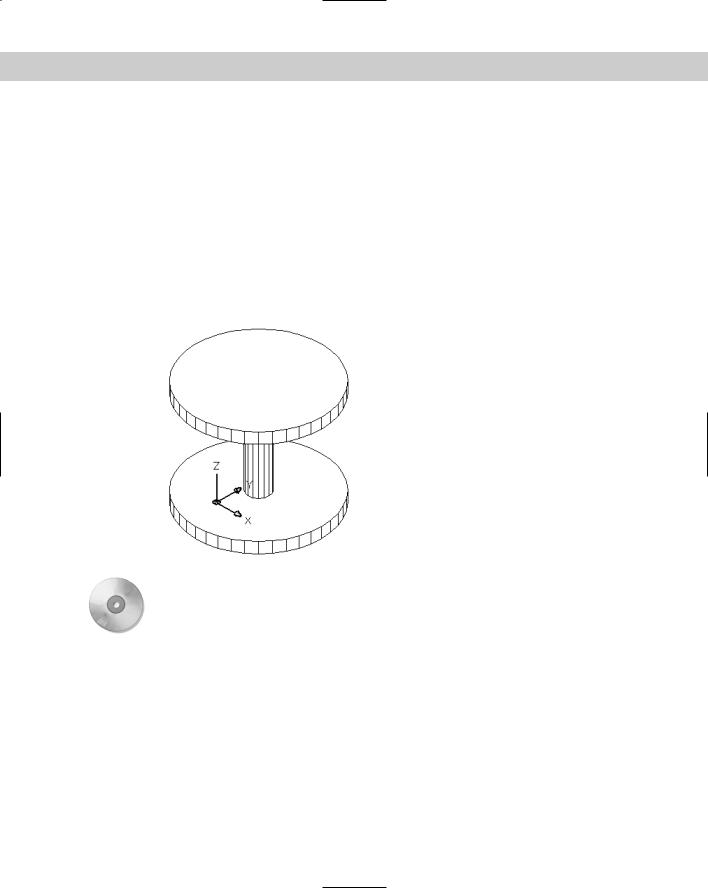
Working with the User Coordinate System
Except for certain true solids, much of 3D work starts with a 2D shape. However, the 2D drawing commands can be drawn only on, or parallel to, the XY plane. The spool in Figure 21-15, for example, consists of three circles, all parallel to the XY plane. How do you draw a circle, or any other 2D object for that matter, that is not parallel to the XY plane?
The answer is to change the User Coordinate System (UCS), thereby changing the definition of the XY plane. You can move the UCS to any location to define the XY plane any way you want. After you do so, you can draw a 2D object at any angle. This section offers a brief review of UCS features that are particularly useful for 3D drawing. (See Chapter 8 for complete coverage of the UCS feature.)
Chapter 21 Specifying 3D Coordinates 609
Using the UCS icon
Although you may have found the UCS icon an annoyance in 2D work, you should display it when working in 3D. Otherwise, it’s easy to lose track of which direction is which. Remember that you can also choose the Origin option, which displays the UCS icon, if possible, at the origin. Choose View Display UCS Icon Origin.
Cross- |
You can customize the look of the UCS icon. The 3D style is helpful when you’re working in |
Reference |
3D. See Chapter 8 for details on customizing the UCS icon display. |
|
UCSs and viewpoints
A plan view of the World UCS (the default) is different from the plan view of a UCS you’ve created by rotating the UCS around the X axis, for example. The UCS defines the orientation and origin of the X, Y, and Z axes. On the other hand, the viewpoint shows your drawing from different angles without changing the orientation or origin of the axes. Understanding the difference between the UCS and viewpoints is important.
The broken pencil
When you choose a viewpoint that shows your drawing from the front, back, or one side instead of the top or an angle, you’re looking straight across the XY plane. This is like looking at a table (which represents the XY plane) by kneeling down so your eyes are exactly at the same height as the surface of the table. From this vantage point, you cannot easily pick objects on the XY plane. A circle looks like a line. In such a situation, if you’ve created a new UCS (not the World UCS) and if you’re using the 2D display of the UCS icon, the UCS icon becomes a brokenpencil icon to warn you that you’re looking at the XY plane of the current UCS edge on.
Figure 21-16 shows the same drawing from three viewpoints: plan view, the SE Isometric view (one of the preset viewpoints), and the front view. From the front view, you see the brokenpencil icon. Notice that the plan (top) view displays even fewer details of the drawing and would also make it difficult to select objects. The middle version uses the SE Isometric preset view, which displays the drawing from above and one corner. This view displays the drawing most clearly.
Express Tools has a command, RTUCS, that enables you to rotate the UCS icon by dragging with the mouse. You can set an incremental angle for rotation and specify an active axis around which you rotate the UCS. Choose Express Tools Real-Time UCS. For information on installing the Express Tools, see Appendix A.
UCS options
To change the UCS, choose one of the UCS menu items on the Tools menu. The following UCS options on the Tools New UCS submenu are useful for 3D drawing.
Object
You can align the UCS with any existing object. Because this option orients the UCS differently for different objects, this option can sometimes be confusing. However, to modify some objects, you must be on its XY plane — a good time to use the Object option. The overall principle is that the UCS’s XY plane stays parallel to the previous UCS, except for 3Dface objects. Table 21-1 explains how the Object option aligns the UCS for various kinds of objects.
610 Part IV Drawing in Three Dimensions
Figure 21-16: Looking at a drawing from different viewpoints in a custom UCS. When you’re looking at the XY plane edge on and are using the 2D UCS icon display, the broken-pencil icon appears.

Chapter 21 Specifying 3D Coordinates 611
|
Table 21-1: UCS Orientation with the Object Option |
|
|
Object |
UCS Orientation |
|
|
Line |
The endpoint nearest your pick point is the origin. The line lies on the X axis. |
2D Polyline |
The endpoint of the polyline nearest your pick point is the origin. The first segment of |
|
the polyline lies on the X axis. |
Dimension |
Places the origin at the midpoint of the dimension text. The X axis is parallel to the X |
|
axis that you used when you created the dimension. |
Text |
Places the origin at the insertion point and aligns the X axis with the rotation angle of |
|
the text. The same applies to attributes. |
Block |
Places the origin at the insertion point and aligns the X axis with the rotation angle of |
|
the block. |
Circle |
The origin is at the circle’s center. The X axis is aligned with your pick point. |
Arc |
The origin is at the arc’s center. The X axis is aligned with the endpoint closest to your |
|
pick point. |
Point |
The origin is at the point. The X axis may be difficult to determine in advance. |
Solid |
Uses the first point you specified for the origin and the first and second points to align |
|
the X axis. AutoCAD LT doesn’t offer solids but you can open AutoCAD drawings |
|
containing solids. |
3Dface |
Uses the first point for the origin. The X axis is aligned with the first two points. The Y |
|
axis is aligned with the first and fourth points. The new UCS may not be parallel to the |
|
prior UCS. AutoCAD LT doesn’t offer 3Dfaces but you can open AutoCAD drawings |
|
containing 3Dfaces. |
|
|
Face
The Face option aligns the UCS on a face of a solid object. At the Select face of solid object: prompt, click within the boundary of a face or on its edge to highlight the face and align the X axis of the UCS with the closest edge of the first face it finds.
At the Enter an option [Next/Xflip/Yflip] <accept>: prompt, you can now refine the UCS. Right-click and choose Next to move the UCS to the adjacent face or the back face of the selected edge. Right-click and choose Xflip to rotate the UCS 180 degrees around the X axis.
Right-click and choose Yflip to rotate the UCS 180 degrees around the Y axis. When you have the UCS you want, press Enter to accept the current location of the UCS.
View
The View option aligns the X and Y axes with the current view. The current origin remains the same. The View option is most often used for creating text that you want to appear flat from your viewpoint of a 3D view of the drawing.
Origin
The Origin option creates a UCS parallel to the current UCS but with a new origin that you specify. You can use the Origin option for working at a new elevation, instead of changing the current elevation.

612 Part IV Drawing in Three Dimensions
Z Axis Vector
The Z Axis Vector option enables you to define an origin and then a point on the positive side of the Z axis. You can keep the previous origin to twist the UCS around its origin.
3Point
The first point you specify is the origin, the second point indicates the positive direction of the X axis, and the third point indicates the positive direction of the Y axis.
X
The X option maintains the current origin and rotates the Y and Z axes around the current
X axis at the rotation angle you specify. The most common rotation is 90 degrees or a multiple of 90 degrees, but you can specify any angle.
Y
The Y option keeps the current origin and rotates the X and Z axes around the current Y axis. You specify the angle.
Z
The Z option keeps the current origin and rotates the X and Y axes around the current Z axis. You specify the angle.
Apply
This option applies the current UCS to a viewport that you specify or to all viewports. This option is not available in AutoCAD LT because you can have only one UCS for all your viewports in AutoCAD LT.
On the |
The drawing used in the following Step-by-Step exercise on creating UCSs, ab21-c.dwg, is |
CD-ROM |
in the Drawings folder on the CD-ROM. |
STEP-BY-STEP: Creating UCSs
1.Open ab21-c.dwg from the CD-ROM.
2.Save it as ab21-04.dwg in your AutoCAD Bible folder. This drawing contains some centerlines based on measurements of a chair. OSNAP should be on. Set running object snaps for endpoint, midpoint, center, and quadrant. The UCS icon is set at the origin.
3.Choose Circle from the Draw toolbar. Use the From object snap to specify the center at @2,0 from 1 in Figure 21-17. Set the radius to 0.5.
4.Choose Properties on the Standard toolbar and select the circle you just drew. Change the thickness to 16. Press Enter. Close the Properties palette (or right-click its title bar and choose Auto-Hide).
5.Click ORTHO on the status bar to turn it on. Choose Mirror from the Modify toolbar. The circle should be selected. (If it isn’t, select it.) Specify the endpoint at 2 for the first point of the mirror line. Specify any point vertical to 2 for the second point of the mirror line. Choose not to delete the source object (the circle).
Chapter 21 Specifying 3D Coordinates 613
6
5 |
7 |
4 |
8 |
|
3 |
|
2 |
1 |
9 |
0
Figure 21-17: These centerlines are the basis for drawing a chair.
6.Repeat the MIRROR command. Select the two circles. Pick the midpoint of the line at 3 for the first point of the mirror line. Pick any point horizontal to the first point for the second point of the mirror line. Press Enter. There are now four legs. Turn ORTHO off.
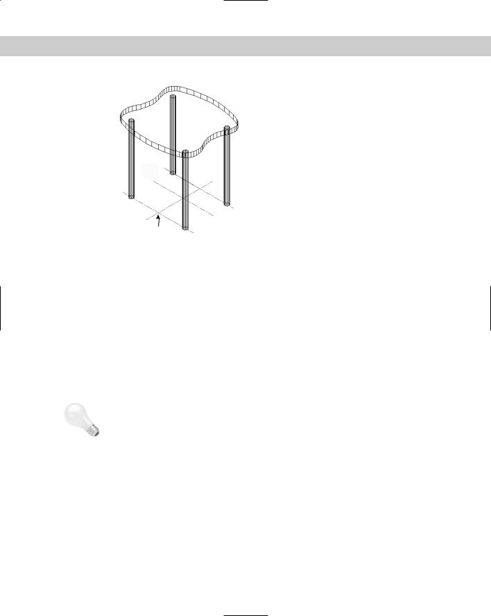
7.Type elev . Change the elevation to 16 and the thickness to 1.
8.Choose View 3D Views SE Isometric. You can now see the four chair legs.
9.Choose Polyline from the Draw toolbar. At the Specify start point: prompt, choose the From object snap. Use the Center object snap of the top of the circle near 1 in Figure 21-17 for the base point and an offset of @–2,0. (You may have to tab to get the Center object snap.) Continue to pick points 4 through 0. Notice that the Endpoint object snap symbol appears at the height of the first point. Then right-click and choose Close to close the polyline.
10.Choose Modify Object Polyline (or type pedit ). Select the polyline. At the prompt, right-click and choose Fit to fit the polyline. Press Enter to end the command.
11.To see the result, type hide . Remember that the polyline has no top or bottom surface. Imagine your model as a glass-bottomed chair. It should look like Figure 21-18.
12.Choose Tools Inquiry List. Select the front-left leg at 1 in Figure 21-18. Press Enter. The center (of the circle at the bottom of the leg) is X = 3.5000; Y = –7.0000; Z = 0.0000.
13.To see the effect of a different UCS option, choose Tools New UCS X. To rotate the UCS around the X axis, type 90 . Again, choose Tools Inquiry List and select the same leg of the chair. Now the center is X = 3.5000, Y = 0.0000, Z = 7.0000. Look at the UCS icon (which is at 0,0,0) and try to visualize why the coordinates are the way they are listed.
614 Part IV Drawing in Three Dimensions
Figure 21-18: Part of a 3D chair.
1
2
3
14.Because you know the center of the circle of the front leg, you can move the UCS there.
Choose Tools New UCS Origin. At the Origin point <0,0,0>: prompt, type 3.5,0,7 . This places the X axis through the center of the circle.
15.Choose Tools New UCS View. The UCS is now parallel to your current view. Choose Draw Text Single-Line Text. Start the text at 2 in Figure 21-18. Set the height to
1.0 and the rotation to 0. Type A glass-bottomed chair. Press Enter twice to end the command.
16.Choose Tools New UCS Object. Pick the line at 3. Choose Tools New UCS Origin. Type 0,0,17 as the origin to place the UCS at the top of the seat.
17.Choose Tools New UCS X. Type –10 to rotate the UCS around the X axis by –10 degrees. This enables you to create the back of the chair at a 10-degree angle. Type plan and press Enter again to accept the default. (This command is covered in the next chapter.) It enables you to view your drawing from plan view (in this case, relative to the current UCS).
Tip Although it’s not necessary for this exercise, this would be a good UCS to save (choose Tools Named UCS and rename the Unnamed current UCS to Chair Back). Having gone through all these steps, it would be a shame to have to re-create the UCS again.
18.With no objects selected, choose Properties on the Standard toolbar. Set the thickness to 16. (The elevation is irrelevant because you’ll use OSNAPS in the next step.) Close the Properties palette.
19.Start the CIRCLE command. Choose the center of the lower circle of the top-left leg (it’s below the chair’s seat) for the center. Accept the default radius of 0.5. Use the same technique to draw a circle at the corresponding right circle. Choose View 3D Views SE Isometric to see the results. Then choose Zoom Previous on the Standard toolbar to return to your previous display.
20.Change the thickness to –5. Type hide so that you can see the circles you just created more clearly.