

18 |
Part I AutoCAD and AutoCAD LT Basics |
Saving a Drawing
Saving a drawing is similar to saving any other file in Windows. You should get in the habit of saving your work every 10 to 15 minutes to avoid losing your work in case your computer system crashes.
Saving a drawing for the first time is different from saving it subsequently because you have to name the drawing the first time you save it.
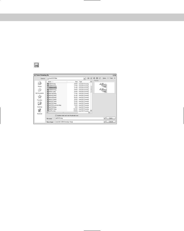
To save a drawing, click Save on the Standard toolbar. If you’re saving a drawing for the first time, the Save Drawing As dialog box appears, as shown in Figure 1-10.
Figure 1-10: The Save Drawing As dialog box.
Down the left side of the dialog box are several buttons to help you find a location to save drawings more quickly. Together, these buttons are called the Places list. Use the Places list as follows:
History lists shortcuts to recently used drawings.
My Documents lists drawings and folders in the My Documents folder. Some people store files in this folder. (Your system may call this the Personal folder.)
Favorites lists files and folders in the C:\Documents and Settings\[login name]\ Favorites folder. (This is the location in Windows XP; it may be different on your computer.) You may have an Autodesk subfolder; if so, double-click the Autodesk subfolder to save a drawing there. Usually, this folder contains only shortcuts to files saved elsewhere. To put a shortcut to an already saved drawing in Favorites, choose File Save As and click the Tools drop-down list; then click Add to Favorites. You can later open the file from the Favorites folder.
Desktop shows drawings on your desktop. Some of the Windows icons also appear on this list.
Buzzsaw sends you to www.buzzsaw.com, the Autodesk business-to-business portal for the building design and construction industry. You can set up a new account or access existing projects.

Chapter 1 Starting to Draw |
19 |
Tip |
In a nice touch, you can reorder the buttons in the Places list. Just drag any button to a new |
|
location. |
|
Of course, you can also choose a location from the Save In drop-down list to save the file to. |
|
To save a file, type a file name in the File Name text box and click Save to save the file. |
|
Use the Views drop-down list of the dialog box to specify how you want to display files in this |
|
dialog box. List just displays the name; Details adds the file size, type, and date modified; and |
|
Preview adds a preview of the drawing. |
|
Use the Tools drop-down list of the dialog box to do the following: |
Add or Modify FTP Locations: FTP sites are locations on the Internet for transferring files. To add or modify FTP locations, choose Tools Add/Modify FTP Locations from the menu of the Save Drawing As dialog box. You need to list the name of the FTP site, choose a logon type (Anonymous or User), and specify your user name and password if you’re logging on as a User. You can then save drawings (called uploading) to FTP locations by clicking the Save In drop-down list and choosing FTP Locations. This feature makes an intranet or any server with FTP capability as accessible as your own computer system.
Add Current Folder to Places: If you save to a specific folder often, you can navigate to that folder and then choose Tools Add Current Folder to Places. The Places Bar then displays a new button for that folder so that you can easily click the button to go straight to the folder.
Add to Favorites: When you have navigated to a folder, you can add it to the Favorites folder by choosing Tools Add to Favorites. You can also select a file in a folder and add it to the Favorites folder.
|
|
The SAVEALL command of the Express Tools saves all open drawings, without closing them. If |
|
|
a drawing hasn’t been saved, you are prompted for a file name. Choose Express File tools |
|
|
Save All Drawings. For information on installing Express Tools, see Appendix A. |
|
|
|
On the |
The CD-ROM includes a small program, savea.lsp, that automatically backs up your draw- |
|
CD-ROM |
ing to the floppy drive after you’ve saved it on your hard drive. If you like to back up to a |
|
|
|
|
|
|
diskette regularly for safety, this program can be useful. Look in \Software\Chap01\ |
|
|
Savea. (AutoCAD only.) |
Closing a Drawing and Exiting from
AutoCAD and AutoCAD LT
|
You can close your drawing and keep AutoCAD or AutoCAD LT open. The simplest way is to |
|
use the drawing Close button just under the application Close button. You can also choose |
|
File Close. |
Tip |
You can choose Window Close All to close all open drawings. If any of the open drawings |
|
have unsaved changes, AutoCAD or AutoCAD LT prompts you to save the changes. If you |
|
have AutoCAD and you installed the Express Tools (see Appendix A for details), you can |
|
choose Express File tools Quick Exit, which closes all open drawings (prompting you to |
|
save if necessary) and then exits the program. |
20 |
Part I AutoCAD and AutoCAD LT Basics |
To exit AutoCAD or AutoCAD LT, click the Close (X) box at the top-right corner of your screen. You can also exit out of AutoCAD or AutoCAD LT by typing quit on the command line and pressing Enter. Another method is to choose File Exit.
If you’ve made any changes to your drawing since last saving it, AutoCAD or AutoCAD LT asks you if you want to save your changes. Choose Yes or No as your situation requires. Choosing Cancel returns you to your drawing. If you have opened more than one drawing to which you have made changes, you have a chance to save each drawing in turn so that you don’t exit AutoCAD or AutoCAD LT without saving all the changes you’ve made in your open drawings.
STEP-BY-STEP: Closing Your Drawing and
Exiting AutoCAD or AutoCAD LT
1.The window of ab01-01.dwg should still be on your screen. Choose File Close. You now see a gray screen with no drawing. (Repeat this process if you have other drawings open. Save or cancel the changes to these extra open drawings as you like.)
2.Click the Close button in the upper-right corner to exit AutoCAD or AutoCAD LT. The program closes immediately.
Summary
Chapter 1 explained how to start AutoCAD and AutoCAD LT and create a new drawing. I gave you a tour of the screen and explained how to save a drawing. This chapter provides the basis for all your work in AutoCAD and AutoCAD LT.
In this chapter, you learned the following:
A brief history of AutoCAD and AutoCAD LT
Some of the different disciplines that use AutoCAD and AutoCAD LT
How to start AutoCAD and AutoCAD LT
How to start a new drawing
The user interface and its various sections, including the drawing area, the UCS icon, the crosshairs, the menus and toolbars, the command line, and the status bar
How to start a command from a toolbar
How to select an object and edit (erase) it
How to draw lines and rectangles
Several ways to specify coordinates, including typing X,Y coordinates and specifying the endpoint of a line
How to save a drawing for the first time
How to close a drawing
How to exit AutoCAD and AutoCAD LT
You may have several questions at this point, but “well begun is half done.” The next chapter explains all the ways to start a new drawing as well as how to open an existing drawing.
|
|
|

Opening a Drawing
AutoCAD and AutoCAD LT offer a number of options for opening new and existing drawings. These options create a great deal of
flexibility and save you time as well. You can create complex templates to avoid doing the same basic setup and drawing over and over.
Creating a New Drawing from a Template
A template is a special file that contains settings and often objects (such as a title block). When you use a template as the basis for a new drawing, the drawing takes on all the settings and objects contained in the template. Use templates to avoid re-creating settings and redrawing objects for new drawings. AutoCAD and AutoCAD LT come with many templates that you can use as is or customize. You can also create your own templates.
Note AutoCAD and AutoCAD LT offer a Startup dialog box that offers choices for starting a new drawing as well as opening existing drawings. To display the Startup dialog box whenever you open AutoCAD or AutoCAD LT, choose Tools Options and click the System tab. In the General Options section, choose Show Startup Dialog Box from the Startup drop-down list. Click OK to close the Options dialog box.
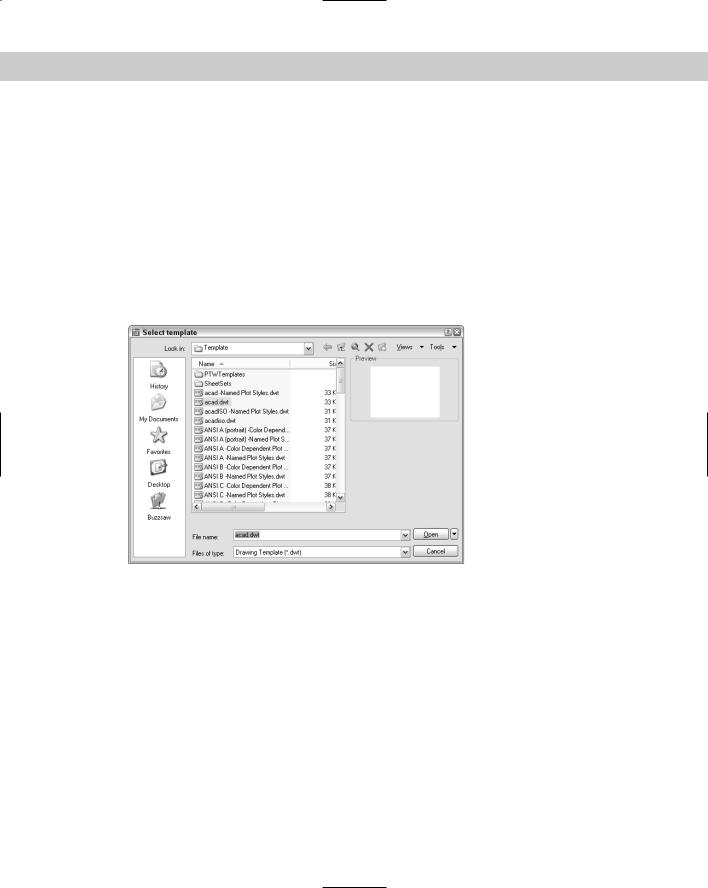
To create a new drawing based on a template, choose File New to open the Select Template dialog box, which lists all the available templates, as shown in Figure 2-1. Click any template to see its preview, if any. Double-click a template to create a new drawing based on that template. Because AutoCAD or AutoCAD LT open with Drawing1.dwg, the new drawing is named Drawing2.dwg. Subsequent drawings that you open are named Drawing3.dwg and so on. When you save and name your drawing, the original template file is unaffected.
The QNEW command is useful if you always start a new drawing based on the same template. You set a default template and
then click QNew on the Standard toolbar to start a new drawing immediately, based on that default template. To set the default template, follow these steps:
1.Choose Tools Options and click the Files tab.
2.Double-click the Drawing Template Settings item.
C 2H A P T E R
In This Chapter
Creating a new drawing from a template
Opening a drawing with default settings
Opening an existing drawing
Using an existing drawing as a prototype
Saving a drawing with a new name
22 |
Part I AutoCAD and AutoCAD LT Basics |
3.Double-click the Default Template File Name for QNEW item.
4.Click the listing under the Default Template File Name for QNEW item (which says None by default).
5.Click Browse to choose the template that you want.
6.Click OK to close the Options dialog box.
You can specify whether this default template uses metric or imperial measurement by setting the MEASUREINIT system variable. (System variables are discussed further in Chapter 5.) On the command line, type measureinit. Enter 0 for imperial units and 1 for metric units.
The default template is acad.dwt for AutoCAD and aclt.dwt for AutoCAD LT. Another default template is acad-Named Plot Styles.dwt or aclt-Named Plot Sytles.dwt, which refers to named plot styles. (See Chapter 17.)
Figure 2-1: Choose a template from the Select Template dialog box.
STEP-BY-STEP: Opening a Drawing
Based on the Default Template
1.Start AutoCAD or AutoCAD LT.
2.Choose File New.
3.From the Select Template dialog box, choose acad.dwt (for AutoCAD) or aclt.dwt (for AutoCAD LT) from the list.
4.Click Open. You now have a blank drawing named Drawing2.dwg, as shown in Figure 2-2.