

- •Foreword
- •Preface
- •Is This Book for You?
- •How This Book Is Organized
- •How to Use This Book
- •Doing the Exercises
- •Conventions Used in This Book
- •What the Icons Mean
- •About the CD-ROM
- •Other Information
- •Contacting the Author
- •Acknowledgments
- •Contents at a Glance
- •Contents
- •Getting Acquainted with AutoCAD and AutoCAD LT
- •Starting AutoCAD and AutoCAD LT
- •Creating a New Drawing
- •Using the AutoCAD and AutoCAD LT Interface
- •Creating Your First Drawing
- •Saving a Drawing
- •Summary
- •Creating a New Drawing from a Template
- •Working with Templates
- •Opening a Drawing with Default Settings
- •Opening an Existing Drawing
- •Using an Existing Drawing as a Prototype
- •Saving a Drawing Under a New Name
- •Summary
- •The Command Line
- •Command Techniques
- •Of Mice and Pucks
- •Getting Help
- •Summary
- •Typing Coordinates
- •Displaying Coordinates
- •Picking Coordinates on the Screen
- •Locating Points
- •Summary
- •Unit Types
- •Drawing Limits
- •Understanding Scales
- •Inserting a Title Block
- •Common Setup Options
- •The MVSETUP Command
- •Summary
- •Using the LINE Command
- •Drawing Rectangles
- •Drawing Polygons
- •Creating Construction Lines
- •Creating Rays
- •Summary
- •Drawing Circles
- •Drawing Arcs
- •Creating Ellipses and Elliptical Arcs
- •Making Donuts
- •Placing Points
- •Summary
- •Panning
- •The ZOOM Command
- •Aerial View
- •Named Views
- •Tiled Viewports
- •Snap Rotation
- •User Coordinate Systems
- •Isometric Drawing
- •Summary
- •Editing a Drawing
- •Selecting Objects
- •Summary
- •Copying and Moving Objects
- •Using Construction Commands
- •Creating a Revision Cloud
- •Hiding Objects with a Wipeout
- •Double-Clicking to Edit Objects
- •Grips
- •Editing with the Properties Palette
- •Selection Filters
- •Groups
- •Summary
- •Working with Layers
- •Changing Object Color, Linetype, and Lineweight
- •Working with Linetype Scales
- •Importing Layers and Linetypes from Other Drawings
- •Matching Properties
- •Summary
- •Drawing-Level Information
- •Object-Level Information
- •Measurement Commands
- •AutoCAD’s Calculator
- •Summary
- •Creating Single-Line Text
- •Understanding Text Styles
- •Creating Multiline Text
- •Creating Tables
- •Inserting Fields
- •Managing Text
- •Finding Text in Your Drawing
- •Checking Your Spelling
- •Summary
- •Working with Dimensions
- •Drawing Linear Dimensions
- •Drawing Aligned Dimensions
- •Creating Baseline and Continued Dimensions
- •Dimensioning Arcs and Circles
- •Dimensioning Angles
- •Creating Ordinate Dimensions
- •Drawing Leaders
- •Using Quick Dimension
- •Editing Dimensions
- •Summary
- •Understanding Dimension Styles
- •Defining a New Dimension Style
- •Changing Dimension Styles
- •Creating Geometric Tolerances
- •Summary
- •Creating and Editing Polylines
- •Drawing and Editing Splines
- •Creating Regions
- •Creating Boundaries
- •Creating Hatches
- •Creating and Editing Multilines
- •Creating Dlines
- •Using the SKETCH Command
- •Digitizing Drawings with the TABLET Command
- •Summary
- •Preparing a Drawing for Plotting or Printing
- •Creating a Layout in Paper Space
- •Working with Plot Styles
- •Plotting a Drawing
- •Summary
- •Combining Objects into Blocks
- •Inserting Blocks and Files into Drawings
- •Managing Blocks
- •Using Windows Features
- •Working with Attributes
- •Summary
- •Understanding External References
- •Editing an Xref within Your Drawing
- •Controlling Xref Display
- •Managing Xrefs
- •Summary
- •Preparing for Database Connectivity
- •Connecting to Your Database
- •Linking Data to Drawing Objects
- •Creating Labels
- •Querying with the Query Editor
- •Working with Query Files
- •Summary
- •Working with 3D Coordinates
- •Using Elevation and Thickness
- •Working with the User Coordinate System
- •Summary
- •Working with the Standard Viewpoints
- •Using DDVPOINT
- •Working with the Tripod and Compass
- •Getting a Quick Plan View
- •Shading Your Drawing
- •Using 3D Orbit
- •Using Tiled Viewports
- •Defining a Perspective View
- •Laying Out 3D Drawings
- •Summary
- •Drawing Surfaces with 3DFACE
- •Drawing Surfaces with PFACE
- •Creating Polygon Meshes with 3DMESH
- •Drawing Standard 3D Shapes
- •Drawing a Revolved Surface
- •Drawing an Extruded Surface
- •Drawing Ruled Surfaces
- •Drawing Edge Surfaces
- •Summary
- •Drawing Standard Shapes
- •Creating Extruded Solids
- •Drawing Revolved Solids
- •Creating Complex Solids
- •Sectioning and Slicing Solids
- •Using Editing Commands in 3D
- •Editing Solids
- •Listing Solid Properties
- •Summary
- •Understanding Rendering
- •Creating Lights
- •Creating Scenes
- •Working with Materials
- •Using Backgrounds
- •Doing the Final Render
- •Summary
- •Accessing Drawing Components with the DesignCenter
- •Accessing Drawing Content with Tool Palettes
- •Setting Standards for Drawings
- •Organizing Your Drawings
- •Working with Sheet Sets
- •Maintaining Security
- •Keeping Track of Referenced Files
- •Handling Errors and Crashes
- •Managing Drawings from Prior Releases
- •Summary
- •Importing and Exporting Other File Formats
- •Working with Raster Images
- •Pasting, Linking, and Embedding Objects
- •Summary
- •Sending Drawings
- •Opening Drawings from the Web
- •Creating Object Hyperlinks
- •Publishing Drawings
- •Summary
- •Working with Customizable Files
- •Creating Keyboard Shortcuts for Commands
- •Customizing Toolbars
- •Customizing Tool Palettes
- •Summary
- •Creating Macros with Script Files
- •Creating Slide Shows
- •Creating Slide Libraries
- •Summary
- •Creating Linetypes
- •Creating Hatch Patterns
- •Summary
- •Creating Shapes
- •Creating Fonts
- •Summary
- •Working with Menu Files
- •Customizing a Menu
- •Summary
- •Introducing Visual LISP
- •Getting Help in Visual LISP
- •Working with AutoLISP Expressions
- •Using AutoLISP on the Command Line
- •Creating AutoLISP Files
- •Summary
- •Creating Variables
- •Working with AutoCAD Commands
- •Working with Lists
- •Setting Conditions
- •Managing Drawing Objects
- •Getting Input from the User
- •Putting on the Finishing Touches
- •Summary
- •Understanding Local and Global Variables
- •Working with Visual LISP ActiveX Functions
- •Debugging Code
- •Summary
- •Starting to Work with VBA
- •Writing VBA Code
- •Getting User Input
- •Creating Dialog Boxes
- •Modifying Objects
- •Debugging and Trapping Errors
- •Moving to Advanced Programming
- •A Final Word
- •Installing AutoCAD and AutoCAD LT
- •Configuring AutoCAD
- •Starting AutoCAD Your Way
- •Configuring a Plotter
- •System Requirements
- •Using the CD with Microsoft Windows
- •What’s on the CD
- •Troubleshooting
- •Index

484 Part II Drawing in Two Dimensions
On the |
Stmplot stamps a drawing with its name and location, your name, the date, and the time, |
CD-ROM |
and starts the PLOT command. Look in \Software\Chap17\Stmplot. (AutoCAD only.) |
The Batch Plotting Utility has been removed. If you need to plot large numbers of drawings or multiple layouts, use the PUBLISH command, which I cover in Chapter 26. (AutoCAD LT does not have a batch publishing feature.)
Summary
In this chapter, you read how to lay out and plot a drawing. You discovered how to:
Lay out a drawing in model space
Use a paper space layout
Create layouts, using the Layout Wizard and using the commands individually
Use the Page Setup dialog box to specify layout settings
Create and apply plot styles
Plot a drawing
This chapter ends Part II, “Drawing in Two Dimensions.” Part III, “Working with Data,” explains how to integrate your drawing with data about your objects. The next chapter explains how to use blocks and attributes.
|
|
|

Working with Data
Part III covers the various ways you work with data in your drawings. This part brings you to a new level of sophistication in
terms of automation and interfacing with other drawings and data. Chapter 18 covers blocks and attributes, which enable you to work repetitively with objects and text. You can use attribute text to create a simple database of information related to your objects. Chapter 19 explains how to refer to other drawings with external references, also called xrefs. Chapter 20 describes how to connect sophisticated external databases to objects in your drawings.
P A R T
III
In This Part
Chapter 18
Working with Blocks and Attributes
Chapter 19
Referencing
Other Drawings
Chapter 20
Working with External Databases


Working with Blocks and Attributes
As you draw, you’ll find that you often need to place the same group of objects several times in a drawing. An architect needs to
place windows and doors many times in a plan layout of a house. An electrical engineer places electrical symbols in a drawing again and again. A mechanical model may include nuts, bolts, and surface finish symbols many times in a drawing. Blocks are groups of objects that you save and name so that you can insert them in your drawing whenever you need them. A block is one object regardless of the number of individual objects that were used to create it. Because it’s one object, you can easily move, copy, scale, or rotate it. However, if necessary, you can explode a block to obtain the original individual objects.
One advantage of blocks is that they reduce the size of the drawing file. A drawing stores the composition of a block only once, along with a simple reference to the block each time it’s inserted, instead of storing each individual object in each block in the drawing database.
As soon as you have a block in a drawing, you can work with it as with any other object. You can snap to object snaps of the individual objects within blocks as well as trim and extend to objects within blocks, even though you can’t edit the individual objects. For example, you can draw a line from the midpoint of a line in a block.
Many disciplines use parts libraries that may consist of thousands of items. You use the block feature to save and insert these parts. You can save many blocks in a drawing or place each in a separate file so that you can insert them in any drawing you wish.
You can attach attributes to blocks. Attributes are labels that are associated with blocks. Attributes have two main uses — to label objects and to create a simple database. If you have AutoCAD, you can use the new field feature in your attributes. (Chapter 13 explains all about fields.)
This chapter explains how to make the most of blocks and attributes.
Combining Objects into Blocks
Any object or set of objects can be saved as a block. Creating a block is easy, but a little planning makes using it much simpler. Before you create a block you need to understand how blocks are inserted and how you want to use the specific block that you’re creating.
18C H A P T E R
In This Chapter
Combining objects into blocks
Saving blocks as drawing files
Inserting blocks and files into drawings
Managing blocks and parts libraries
Using Windows features
Working with attributes
488 Part III Working with Data
Understanding base points and insertion points
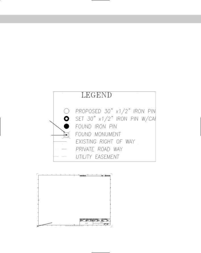
Figure 18-1 shows the legend for a plat drawing. Each legend symbol is a block that is then inserted in the drawing as needed. The first symbol has been selected, and you can see that it has one grip at the base point. The base point is the point you use to insert the block. Every block must have a base point. When you insert the block, the base point is placed at the coordinate you specify for inserting the block — the insertion point. All the objects of the block are then inserted in their proper place relative to that insertion point.
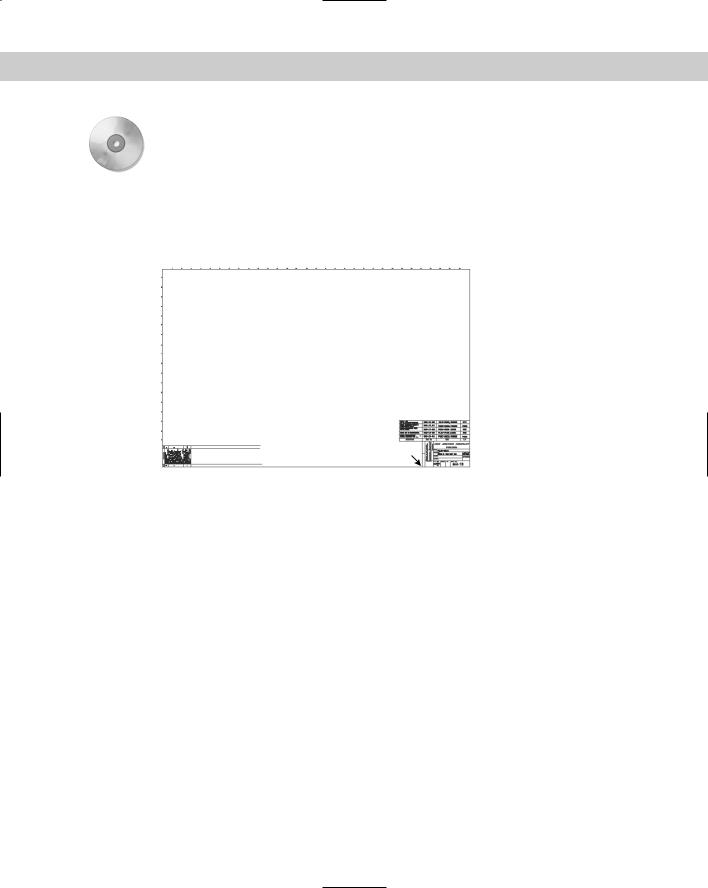
The base point does not have to be on the object, but it should be in a location that makes it easy to insert the block. Figure 18-2 shows a different sort of block — a title border/block. In this case, the base point is usually inserted at 0,0 of the drawing. By placing the base point at the lower-left corner of the border, you can easily place this block in any drawing. The base point is similar in concept to the justification point on text objects.
Block
Base point
Figure 18-1: Each legend symbol is a block. Every block has a base point.
Figure 18-2: This block is a title block. Its base point is at the lower-left corner.
 Block
Block
Base point
Chapter 18 Working with Blocks and Attributes |
489 |
Creating a block
To create a block, first create the objects just as you want to save them. You may include other blocks as objects in your block. (A block within a block is called a nested block.)
After you’ve created the objects for your block, follow these steps:
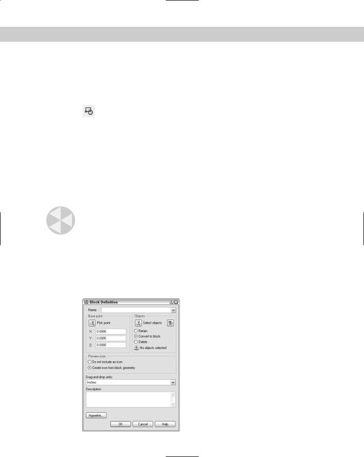
1.Choose Make Block from the Draw toolbar to start the BLOCK command and open the Block Definition dialog box, shown in Figure 18-3. The dialog box guides you
through the process of defining a block.
2.In the Name text box, type a name for the block (up to 255 characters; spaces allowed).
3.Click Select Objects. You return to your drawing temporarily. Use any selection method to select the objects you want in your block. Press Enter to end selection and return to the Block Definition dialog box. (If you select the objects before starting the command, you skip this step. The dialog box notes how many objects are selected.) To filter out the selected objects, choose Quick Select (described in Chapter 10).
4.Choose a base point. By default, the base point is 0,0 (or 0,0,0 for 3D drawings). To define any other point, such as an object snap on any of the objects in the block, click Pick Point. You return to your drawing temporarily. At the Specify insertion base point: prompt, specify a point, which returns you to the dialog box.
Caution |
For precision, you should always use an object snap when defining the base point. If the |
|
base point you need to use is not on any object, you can use the From object snap, tracking, |
|
or some other means of specifying a precise coordinate. |
5.Choose how you want the objects of the block to be treated:
•If you want to keep the objects that you selected as individual objects, check Retain.
•If you created the objects to insert them elsewhere and do not need the original objects, check Delete.
•To convert the objects to a block, check Convert to Block.
Figure 18-3: The Block Definition dialog box.
490 Part III Working with Data
6.By default, a block includes an icon based on the block. If you later use the DesignCenter to insert the block in another drawing, this icon will appear in the preview box to help you decide which block you want to insert. Click Do Not Include an Icon if you don’t want one.
7.Choose the insert units you want to use when defining your block. (You can choose anything from microns to parsecs!) Let’s say you work in kilometers and save a block with an insert unit of kilometers. When you insert a block, it will be measured in kilometers, rather than millimeters or inches. If the units aren’t important to you, you can specify the units as Unitless.
8.If you want, enter a description for the block. As with the icon described in Step 6, the description is used by the DesignCenter. You can also add a hyperlink by clicking the Hyperlink button. (See Chapter 28 for more on hyperlinks.)
9.Click OK to return to your drawing.
The definition of the block is now stored in the drawing, ready for you to insert as many times as needed. If you checked Delete, your objects disappeared. You can retrieve them by the one command with a sense of humor — OOPS. OOPS restores the last object or set of objects you erased — whether by using the ERASE command or by creating a block, even if you used some other command in the meantime. By contrast, UNDO undoes almost all commands, but only in the order they were executed.
Tip |
If you create a number of block definitions that you don’t end up using in the drawing, use the |
|
PURGE command to delete them. This reduces the size of the drawing file. |
Redefining a block
One advantage of deleting the objects is that their disappearance confirms that you selected the right objects. If you make a mistake, or if you want to change the block in some way, you can redefine it. If you just created the block, use UNDO and make any necessary changes. If you created the block earlier, follow these steps:
1.Insert the block and explode it. (Exploding is covered later in this chapter.)
2.Make the desired changes and repeat the process of defining the block, using the same name for the block.
Caution |
When you specify the name of the block, you should type it, rather than choose it from the |
|
Name drop-down list. Choosing the name from the list replaces selected objects (that you |
|
wanted to be in the new version of the block) with the objects from the previous block defi- |
|
nition and sets the insertion point to 0,0. |
3. Click Yes when the message asks if you want to redefine the block.
Redefining a block that has been inserted in your drawing updates all the blocks. This is a powerful technique to control your drawing. If you have repetitive symbols in your drawing, it’s worthwhile to make blocks out of them just so that you can make this type of global change if necessary.
On the |
The drawing that you need for the following Step-by-Step exercise on creating a block, ab18- |
CD-ROM |
a.dwg, is in the Drawings folder on the CD-ROM. |
Chapter 18 Working with Blocks and Attributes |
491 |
STEP-BY-STEP: Creating a Block
1.Open ab18-a.dwg from the CD-ROM.
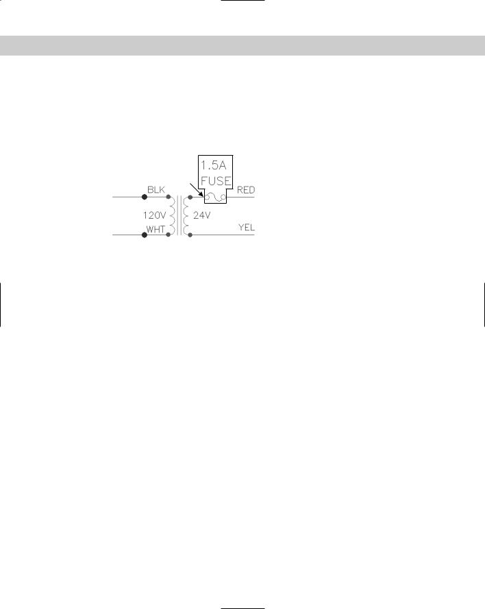
2.Save the file as ab18-01.dwg in your AutoCAD Bible folder. This is a small portion of an electrical schematic drawing, as shown in Figure 18-4. OSNAP should be on. Set running object snaps for endpoint, quadrant, and intersection.
Figure 18-4: A portion of an electrical schematic.
1
3. To make a block of the 1.5 amp fuse, choose Make Block from the Draw toolbar.
4.In the Name text box of the Block Definition dialog box, type 1-5 amp fuse.
5.Click Select objects to return to the drawing temporarily.
6.Select the boxed objects shown in Figure 18-4 (the two lines of text, the two circles, and the two arcs). Press Enter to end selection and return to the dialog box. Under the Select Objects button, the dialog box displays 6 objects selected.
7.Click Pick Point in the Base Point section of the dialog box.
8.In the drawing, use the Quadrant object snap to pick 1 in Figure 18-4.
9.In the dialog box, check Delete. Create Icon from Block Geometry should be checked. The Insert Units should be Unitless. Leave the Description blank. Click OK to return to your drawing. This action erases the objects that made up the block.
10.To check that the block has been created, choose Make Block from the Draw toolbar. Click the Name drop-down arrow to see your block. Click Cancel.
11.Save your drawing.
Saving blocks as files
You can use the DesignCenter to insert blocks from any drawing. Nevertheless, many users need to organize their blocks in their own files so they can be easily stored and located. Parts and symbols libraries are made up of many individual drawing files, one for each part or symbol. Such libraries are a powerful aid to drawing more efficiently.
To save a block as a file, follow these steps:
1.Type wblock . (WBLOCK stands for write block. Writing to a file is another expression for saving to a file.)
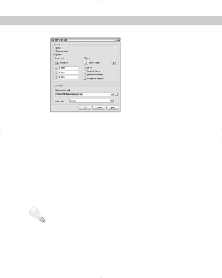
2.In the Write Block dialog box, shown in Figure 18-5, choose the location (drive and folder) for the file.
492 Part III Working with Data
Figure 18-5: Use the Write Block dialog box to save a block as a separate drawing file.
3.In the Source section, choose how you want to create the drawing file:
•Block: Use this option when you’ve already created the block and now want to save it as a drawing file. Choose the block from the drop-down list.
•Entire drawing: Use this option to make a copy of your drawing.
•Objects: Use this option to start defining the block in the same way you define a block within a drawing. The Base Point and Objects sections become available.
4.In the File Name and Path text box, type the path and name of the file you want to create. (You can also click the ellipsis button to navigate to a location and then type a filename in the Browse for Drawing File dialog box. Click Save to return to the Write Block dialog box.) If you’ve already created the block in your drawing, you should generally use the same name as the block to avoid confusion, but you might have special naming conventions for a block library.
5.In the Insert Units drop-down list, choose the units you want for your block or choose Unitless for no units.
6.After you’re done, click OK to create the drawing file.
Tip |
When you save a drawing that you plan to insert as a block, use the BASE command to create |
|
the insertion point. By default, the base point is 0,0,0. By setting the base point to another |
|
point in the drawing, such as an object snap on one of the objects, you can control how that |
|
drawing is inserted. |
Replacing an existing file
If you make a mistake when selecting objects to write to a file with WBLOCK, or want to change the objects in the file, you can replace the file. Start WBLOCK and type the name of the block file you want to change. Be sure to choose the same file location. When you click OK, a message asks if you want to replace the existing file. Click Yes.
Chapter 18 Working with Blocks and Attributes |
493 |
On the |
The drawing that you need for the following Step-by-Step exercise on saving a block to a file, |
CD-ROM |
ab18-b.dwg, is in the Drawings folder on the CD-ROM. |
STEP-BY-STEP: Saving a Block to a File
1.Open ab18-b.dwg from the CD-ROM.
2.Save the file as ab18-02.dwg in your AutoCAD Bible folder. This is a large title block, as shown in Figure 18-6. OSNAP should be on. Set a running object snap for endpoint.
1
Figure 18-6: A title block can be saved as a file and inserted into any other drawing.
3.Type wblock . In the Source section of the Write Block dialog box, click Entire drawing. Set the File Name and Path box to AutoCAD Bible\tb-f by typing the path and the filename. (Alternatively, click the ellipsis [...] button and navigate to your AutoCAD Bible folder. In the File Name text box, type tb-f. Click Save.) Click OK.
4.Press Enter to repeat the WBLOCK command.
5.In the Source section of the dialog box, choose Objects. In the Objects section, click Select Objects.
6.Use Zoom Window to zoom in on the text at the bottom-right corner of the title block. At the Select objects: prompt, select all the 90° rotated text at 1 in Figure 18-6. Press Enter to end selection.
7.In the Base Point section, click Pick Point. Use the Endpoint object snap to pick the bottom-left corner of the box containing the text you selected. Using this base point lets you easily place the text in the box at any time.
8.In the Object section, choose Delete from Drawing.
9.In the File Name and Path text box, type notes-tol after the path, which should already be set to your AutoCAD Bible folder. Click OK to save the block as a file.
10.Type oops to bring back the text.
11.Choose Zoom Extents from the Zoom flyout of the Standard toolbar. Save your drawing.