

- •Foreword
- •Preface
- •Is This Book for You?
- •How This Book Is Organized
- •How to Use This Book
- •Doing the Exercises
- •Conventions Used in This Book
- •What the Icons Mean
- •About the CD-ROM
- •Other Information
- •Contacting the Author
- •Acknowledgments
- •Contents at a Glance
- •Contents
- •Getting Acquainted with AutoCAD and AutoCAD LT
- •Starting AutoCAD and AutoCAD LT
- •Creating a New Drawing
- •Using the AutoCAD and AutoCAD LT Interface
- •Creating Your First Drawing
- •Saving a Drawing
- •Summary
- •Creating a New Drawing from a Template
- •Working with Templates
- •Opening a Drawing with Default Settings
- •Opening an Existing Drawing
- •Using an Existing Drawing as a Prototype
- •Saving a Drawing Under a New Name
- •Summary
- •The Command Line
- •Command Techniques
- •Of Mice and Pucks
- •Getting Help
- •Summary
- •Typing Coordinates
- •Displaying Coordinates
- •Picking Coordinates on the Screen
- •Locating Points
- •Summary
- •Unit Types
- •Drawing Limits
- •Understanding Scales
- •Inserting a Title Block
- •Common Setup Options
- •The MVSETUP Command
- •Summary
- •Using the LINE Command
- •Drawing Rectangles
- •Drawing Polygons
- •Creating Construction Lines
- •Creating Rays
- •Summary
- •Drawing Circles
- •Drawing Arcs
- •Creating Ellipses and Elliptical Arcs
- •Making Donuts
- •Placing Points
- •Summary
- •Panning
- •The ZOOM Command
- •Aerial View
- •Named Views
- •Tiled Viewports
- •Snap Rotation
- •User Coordinate Systems
- •Isometric Drawing
- •Summary
- •Editing a Drawing
- •Selecting Objects
- •Summary
- •Copying and Moving Objects
- •Using Construction Commands
- •Creating a Revision Cloud
- •Hiding Objects with a Wipeout
- •Double-Clicking to Edit Objects
- •Grips
- •Editing with the Properties Palette
- •Selection Filters
- •Groups
- •Summary
- •Working with Layers
- •Changing Object Color, Linetype, and Lineweight
- •Working with Linetype Scales
- •Importing Layers and Linetypes from Other Drawings
- •Matching Properties
- •Summary
- •Drawing-Level Information
- •Object-Level Information
- •Measurement Commands
- •AutoCAD’s Calculator
- •Summary
- •Creating Single-Line Text
- •Understanding Text Styles
- •Creating Multiline Text
- •Creating Tables
- •Inserting Fields
- •Managing Text
- •Finding Text in Your Drawing
- •Checking Your Spelling
- •Summary
- •Working with Dimensions
- •Drawing Linear Dimensions
- •Drawing Aligned Dimensions
- •Creating Baseline and Continued Dimensions
- •Dimensioning Arcs and Circles
- •Dimensioning Angles
- •Creating Ordinate Dimensions
- •Drawing Leaders
- •Using Quick Dimension
- •Editing Dimensions
- •Summary
- •Understanding Dimension Styles
- •Defining a New Dimension Style
- •Changing Dimension Styles
- •Creating Geometric Tolerances
- •Summary
- •Creating and Editing Polylines
- •Drawing and Editing Splines
- •Creating Regions
- •Creating Boundaries
- •Creating Hatches
- •Creating and Editing Multilines
- •Creating Dlines
- •Using the SKETCH Command
- •Digitizing Drawings with the TABLET Command
- •Summary
- •Preparing a Drawing for Plotting or Printing
- •Creating a Layout in Paper Space
- •Working with Plot Styles
- •Plotting a Drawing
- •Summary
- •Combining Objects into Blocks
- •Inserting Blocks and Files into Drawings
- •Managing Blocks
- •Using Windows Features
- •Working with Attributes
- •Summary
- •Understanding External References
- •Editing an Xref within Your Drawing
- •Controlling Xref Display
- •Managing Xrefs
- •Summary
- •Preparing for Database Connectivity
- •Connecting to Your Database
- •Linking Data to Drawing Objects
- •Creating Labels
- •Querying with the Query Editor
- •Working with Query Files
- •Summary
- •Working with 3D Coordinates
- •Using Elevation and Thickness
- •Working with the User Coordinate System
- •Summary
- •Working with the Standard Viewpoints
- •Using DDVPOINT
- •Working with the Tripod and Compass
- •Getting a Quick Plan View
- •Shading Your Drawing
- •Using 3D Orbit
- •Using Tiled Viewports
- •Defining a Perspective View
- •Laying Out 3D Drawings
- •Summary
- •Drawing Surfaces with 3DFACE
- •Drawing Surfaces with PFACE
- •Creating Polygon Meshes with 3DMESH
- •Drawing Standard 3D Shapes
- •Drawing a Revolved Surface
- •Drawing an Extruded Surface
- •Drawing Ruled Surfaces
- •Drawing Edge Surfaces
- •Summary
- •Drawing Standard Shapes
- •Creating Extruded Solids
- •Drawing Revolved Solids
- •Creating Complex Solids
- •Sectioning and Slicing Solids
- •Using Editing Commands in 3D
- •Editing Solids
- •Listing Solid Properties
- •Summary
- •Understanding Rendering
- •Creating Lights
- •Creating Scenes
- •Working with Materials
- •Using Backgrounds
- •Doing the Final Render
- •Summary
- •Accessing Drawing Components with the DesignCenter
- •Accessing Drawing Content with Tool Palettes
- •Setting Standards for Drawings
- •Organizing Your Drawings
- •Working with Sheet Sets
- •Maintaining Security
- •Keeping Track of Referenced Files
- •Handling Errors and Crashes
- •Managing Drawings from Prior Releases
- •Summary
- •Importing and Exporting Other File Formats
- •Working with Raster Images
- •Pasting, Linking, and Embedding Objects
- •Summary
- •Sending Drawings
- •Opening Drawings from the Web
- •Creating Object Hyperlinks
- •Publishing Drawings
- •Summary
- •Working with Customizable Files
- •Creating Keyboard Shortcuts for Commands
- •Customizing Toolbars
- •Customizing Tool Palettes
- •Summary
- •Creating Macros with Script Files
- •Creating Slide Shows
- •Creating Slide Libraries
- •Summary
- •Creating Linetypes
- •Creating Hatch Patterns
- •Summary
- •Creating Shapes
- •Creating Fonts
- •Summary
- •Working with Menu Files
- •Customizing a Menu
- •Summary
- •Introducing Visual LISP
- •Getting Help in Visual LISP
- •Working with AutoLISP Expressions
- •Using AutoLISP on the Command Line
- •Creating AutoLISP Files
- •Summary
- •Creating Variables
- •Working with AutoCAD Commands
- •Working with Lists
- •Setting Conditions
- •Managing Drawing Objects
- •Getting Input from the User
- •Putting on the Finishing Touches
- •Summary
- •Understanding Local and Global Variables
- •Working with Visual LISP ActiveX Functions
- •Debugging Code
- •Summary
- •Starting to Work with VBA
- •Writing VBA Code
- •Getting User Input
- •Creating Dialog Boxes
- •Modifying Objects
- •Debugging and Trapping Errors
- •Moving to Advanced Programming
- •A Final Word
- •Installing AutoCAD and AutoCAD LT
- •Configuring AutoCAD
- •Starting AutoCAD Your Way
- •Configuring a Plotter
- •System Requirements
- •Using the CD with Microsoft Windows
- •What’s on the CD
- •Troubleshooting
- •Index
Chapter 14 Drawing Dimensions 365
Using Quick Dimension
Quick Dimension enables you to dimension several objects at one time. You can use Quick Dimension for baseline, continued, and ordinate dimensions. You can also dimension multiple circles and arcs. Later in this chapter, I explain how you can use Quick Dimension to edit dimensions as well. Although Quick Dimension may seem like the answer to all your dimensionrelated prayers, you can’t use it in every case. However, it works well in mass-production situations. Dimensions created with the QDIM command are fully associative, so that any changes you make to objects automatically update their associated dimensions.
The Quick Dimension feature is not available in AutoCAD LT.
Here’s how it works, in three easy steps:
On the
CD-ROM
1. Choose Quick Dimension from the Dimension toolbar.
2.At the Select geometry to dimension: prompt, select all the objects you want to
dimension. You can’t use object snaps; you need to select objects. If you select an object in error, type r and then pick the object again to remove it. Then type a to start adding objects again.
3.At the Specify dimension line position, or [Continuous/Staggered/Baseline/ Ordinate/Radius/Diameter/datumPoint/Edit/SeTtings]<Continuous>: prompt, right-click and choose the type of dimension you want to create. Figure 14-29 shows a set of continuous dimensions. The Datum Point option sets a new base point for baseline and ordinate dimensions. You can press Enter to use the type of dimension you used just previously because that shows as the default. The command immediately creates the dimensions for you.
Figure 14-29: A set of continuous dimensions created with Quick
Dimension.
The drawing used in the following Step-by-Step exercise on using Quick Dimension to create dimensions, ab14-f.dwg, is in the Drawings folder on the CD-ROM.
STEP-BY-STEP: Using Quick Dimension to Create Dimensions
1.Open ab14-f.dwg from your CD-ROM.
2.Save the file as ab14-07.dwg in your AutoCAD Bible folder. This is the same drawing you used in the previous exercise, except that some of the dimensions have been removed (see Figure 14-30). OSNAP should be turned off. If the Dimension toolbar isn’t displayed, right-click any toolbar and choose Dimension.
366 Part II Drawing in Two Dimensions
1 2
3 |
|
4 |
7 |
5 |
6 |
Figure 14-30: You can use Quick Dimension to dimension the circles and create continuous dimensions.
3.Choose Quick Dimension from the Dimension toolbar. Follow the prompts:
Select geometry to dimension: Pick the circle at 1 in Figure 14-30.
Select geometry to dimension: Pick the circle at 2 in Figure 14-30.
Select geometry to dimension: Specify dimension line position, or
[Continuous/Staggered/Baseline/Ordinate/Radius/Diameter/datum Point/ Edit/SeTtings]
<Staggered>: Right-click and choose Radius.
Specify dimension line position, or [Continuous/Staggered/Baseline/Ordinate/Radius/Diameter/datum Point/ Edit/SeTtings]
<Radius>: Pick a point on the left circle at about 80 degrees from the right quadrant.
Quick Dimension places the radius dimensions.
4.Repeat the QDIM command. Follow the prompts:
Select geometry to dimension: Pick the line at 3 in Figure 14-30.
Select geometry to dimension: Pick the line at 4.
Select geometry to dimension: Pick the vertical centerline at 5. Select geometry to dimension: Pick the vertical centerline at 6.
Select geometry to dimension: Pick the line at 7. Select geometry to dimension:
Specify dimension line position, or [Continuous/Staggered/Baseline/Ordinate/Radius/Diameter/datumPoint/ Edit/SeTtings]
<Staggered>: Right-click and choose Baseline.
Specify dimension line position, or [Continuous/Staggered/Baseline/Ordinate/Radius/Diameter/datumPoint/ Edit/SeTtings]
<Baseline>: Pick a point below the model.
Quick Dimension places the baseline dimensions.
Chapter 14 Drawing Dimensions 367
Figure 14-31: The model with added radius and baseline dimensions.
5. Save your drawing. It should look approximately like Figure 14-31.
Editing Dimensions
Dimensions have many properties — text size, arrowhead size, text placement, and so on. You change most of these properties by changing the dimension style — either globally changing all dimensions using that style or overriding a dimension style setting for a particular dimension. The next chapter covers dimension styles, but here I cover several other ways to edit dimensions.
Editing associativity
By default, new drawings created in AutoCAD 2005 and AutoCAD LT 2005 are associative. However, drawings created in releases prior to 2002 do not have the new associativity.
The DIMASSOC system variable specifies whether dimensions are associative. Here are the settings:
0 creates exploded dimensions. Each part of the dimension is a separate object and there is no association between the dimension and the object it dimensions.
1 creates nonassociative dimensions. The dimension is all one object but is not updated if the object it dimensions is changed.
2 creates associative dimensions. The dimension is all one object and is updated if the object it dimensions is changed.
368 Part II Drawing in Two Dimensions
DIMREASSOCIATE
Use the DIMREASSOCIATE command to associate dimensions with their objects. You need to use this command when you open drawings created in releases prior to 2002 in AutoCAD 2005 or AutoCAD LT 2005. You might also need to use this command when dimensions become disassociated from their objects, perhaps through some editing process, or to reassociate dimensions after you’ve disassociated them for some reason.
To use DIMREASSOCIATE, follow these steps:
1.Choose Dimension Reassociate Dimensions.
2.At the Select objects: prompt, select the dimensions that you want to associate. Press Enter to end object selection.
You see a prompt that varies according to the type of dimension you’ve selected. For example, for linear dimensions, you see the Specify first extension line origin or [Select object] <next>: prompt. At the same time, you see a marker in the form of an X that corresponds to the prompt, as shown in Figure 14-32. The marker indicates an association point (a point that connects an object and all or part of its dimension). If the X has a box around it, the dimension is already associated with the point marked by the X.
Note If you use the wheel of a mouse to pan or zoom, the X disappears. Press Esc and start the command again or type ‘redraw .
Figure 14-32: When you associate a dimension with an object, an association point appears on the object.
3.Use an object snap to specify the location of the X (whether the same as shown or a different location) or use the Select Object option to select an object (right-click and choose Select Object). To skip to the next prompt, without associating the dimension to the marked point, press Enter.
4.Continue to respond to the prompts in turn. The command prompts you through all the dimensions you selected.
Chapter 14 Drawing Dimensions 369
Caution |
When specifying object snaps, be careful that you choose the point you want. For example, if |
|
you use an Endpoint object snap where two lines meet, you cannot be sure which line’s end- |
|
point you’ve chosen. When you move or stretch the line you expect to be associated with the |
|
dimension, you may find that the dimension doesn’t budge. That’s because it’s actually asso- |
|
ciated with a different line. Selecting the object itself is often a better solution, because the |
|
dimension is associated with the object. |
DIMDISASSOCIATE
Occasionally, you may want to edit a dimension in such a way that you need to remove its associativity. Perhaps you need to squeeze it into a tight corner. For these times, use the DIMDISASSOCIATE command by typing it on the command line. At the prompt, select the dimensions that you want to disassociate from their objects.
Note |
You cannot disassociate dimensions that are on locked layers. Unlock the layer first and then |
|
disassociate the dimension. |
DIMREGEN
The DIMREGEN command updates the locations of all associative dimensions. This command is only needed in three unusual situations:
If you pan or zoom with a wheel mouse in a paper space layout while model space is active
If you open a drawing containing dimensioned objects that have been edited with a previous version of AutoCAD or AutoCAD LT
If you open a drawing containing external references that are dimensioned in the current drawing and dimensioned objects in the external reference have been changed
Using the DIMEDIT command
The DIMEDIT command offers four ways to edit dimensions. The advantage of this command is that you can change more than one dimension at a time. Choose Dimension Edit
from the Dimension toolbar. The command responds with the Enter type of dimension editing [Home/New/Rotate/Oblique] <Home>: prompt. Right-click to choose one of the options:
Home: Moves dimension text to its default position as defined by the dimension style.
New: Lets you type new text to replace the existing text. The Multiline Text Editor opens, showing the angle brackets that represent the dimension text. You can use this option to add a suffix, such as TYP (typical) to several dimensions.
Rotate: Rotates the dimension text. This works like the rotation angle for text.
Oblique: Angles the extension lines of the dimension. Use this when you have several dimensions close together that interfere with each other. Specify the final angle of the extension lines, not the rotation from the current angle.
Note The Oblique item on the Dimension menu executes the DIMEDIT command with the Oblique option.
370 Part II Drawing in Two Dimensions
As soon as you choose an option, DIMEDIT prompts you to select objects. You can select as many dimensions as you wish. You have the opportunity to use the DIMEDIT command in an exercise after the next section.
Using the DIMTEDIT command
The DIMTEDIT command repositions dimension text. To start the command, choose Dimension Text Edit from the Dimension toolbar. Although its name gives the impression that you can edit the text content, you can only change its position. Also, you can only
edit one dimension at a time. The command responds with the Select dimension: prompt. Select a dimension.
At the Specify new location for dimension text or [Left/Right/Center/Home/ Angle]: prompt, you can use the cursor to pick a text location. You can also right-click and choose one of the options:
On the
CD-ROM
Left: Left-justifies the text of linear, radial, or diameter dimensions.
Right: Right-justifies the text of linear, radial, or diameter dimensions.
Center: Centers the text of linear, radial, or diameter dimensions.
Home: Returns dimension text to its default position and angle.
Angle: Rotates dimension text. This option is equivalent to the Rotate option of the DIMEDIT command.
The drawing used in the following Step-by-Step exercise on using DIMEDIT and DIMTEDIT to edit dimensions, ab14-g.dwg, is in the Drawings folder on the CD-ROM.
STEP-BY-STEP: Using DIMEDIT and
DIMTEDIT to Edit Dimensions
1.Open ab14-g.dwg from your CD-ROM.
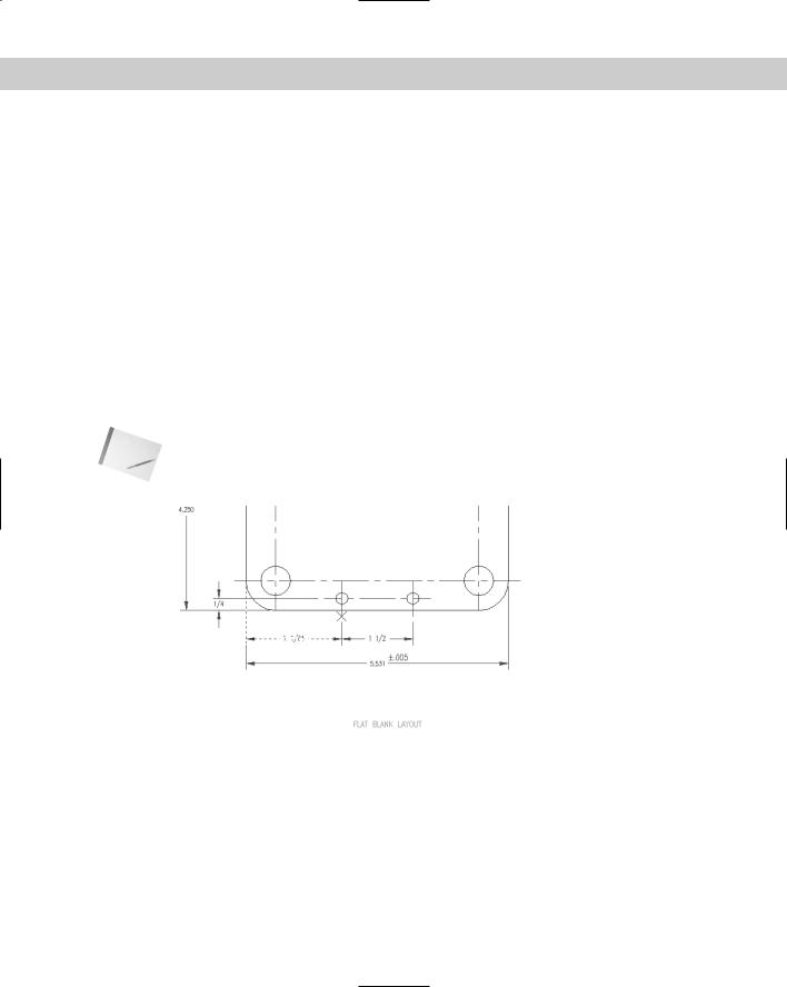
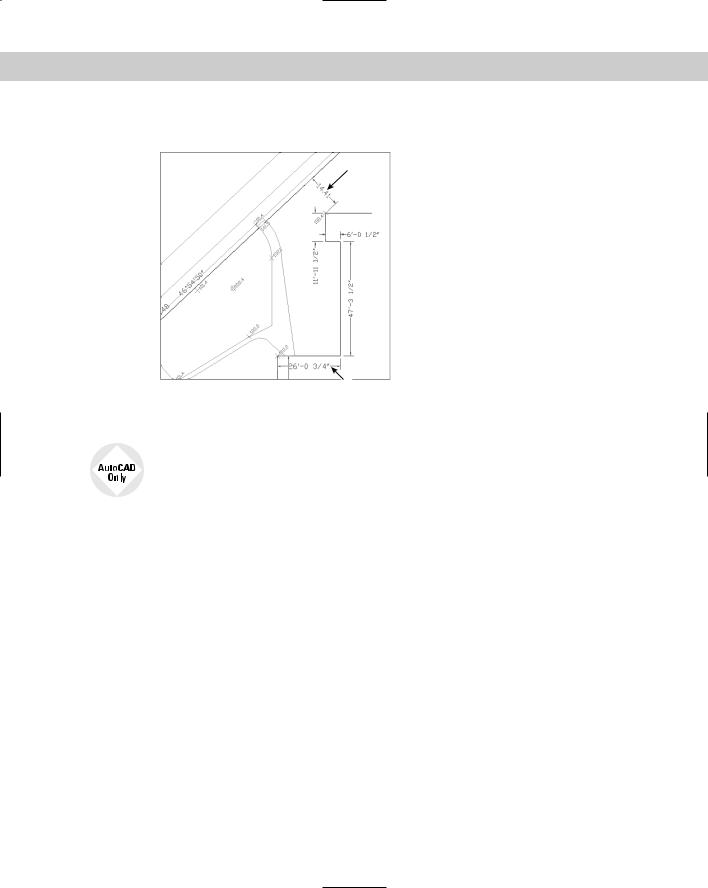
2.Save the file as ab14-08.dwg in your AutoCAD Bible folder. This is a civil engineering drawing whose dimensions need some editing (see Figure 14-33). If the Dimension toolbar isn’t visible, right-click any toolbar and check Dimension.
3.The dimension at 1 in Figure 14-33 is not in the proper units because the text was entered explicitly as 14.41. To correct this error, choose Dimension Edit from the
Dimension toolbar. At the Enter type of dimension editing [Home/New/Rotate/ Oblique] <Home>: prompt, right-click and choose New. The Multiline Text Editor opens, showing the angle brackets. Because you want the original text, click OK. At the Select objects: prompt, pick 1. Press Enter to end object selection. (You could correct several dimensions this way.) This action corrects the dimension, automatically creating the text in the current units.
4.The dimension text at 2 in Figure 14-33 is too close to the dimension line of the vertical dimension that crosses it. Choose Dimension Text Edit from the
Dimension toolbar. At the Select dimension: prompt, pick 2. At the Specify new location for dimension text or [Left/Right/Center/Home/Angle]: prompt, right-click and choose Right. This action moves the text to the right.
Chapter 14 Drawing Dimensions 371
5. Save your drawing.
1
2
Figure 14-33: A dimensioned civil engineering drawing.
The Express Tools command, DIMREASSOC, does the same thing you accomplished in Step 3 of this exercise — restoring the default measurement value to modified dimension text. Choose Express Dimension Reset Dim Text Value. For information about installing Express Tools, see Appendix A.
Editing dimension text
You can edit dimension text as you would any other multiline text object. Choose Modify Object Text Edit. At the Select an annotation object or [Undo]: prompt, choose the dimension. The Multiline Text Editor opens. Using the Multiline Text Editor for dimension text has already been covered in this chapter under the MText option of the dimensioning commands.
Using the Properties palette to edit dimensions
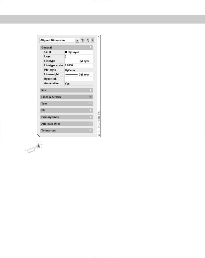
You can edit dimensions by using the Properties palette just as you can edit the properties of any other object. Double-click any dimension to open the Properties palette. You see the properties of the dimensions that you can edit, as shown in Figure 14-34.
Parts of this palette make more sense after you learn about dimension styles, which are covered in the next chapter. For example, the listings for Primary Units, Alternate Units, Fit, Lines & Arrows, Text, and so on duplicate the tabs on the New Dimension Style and Modify Dimension Style dialog boxes. You can change the color, layer, lineweight, and linetype. To override the automatic dimension text, enter the text in the Text Override field of the Text section of the Properties palette.
372 Part II Drawing in Two Dimensions
Figure 14-34: The Properties palette as it appears with one aligned dimension selected.
New |
You can create a background mask like the one you can create for multiline text. (For more |
Feature |
information, see Chapter 13.) If dimension text covers other objects, select the dimension |
|
|
|
and open the Properties palette (Ctrl+1). Choose an option from the Text Fill item. For the |
|
background mask to work, the dimension needs to be on top of any other objects that it |
|
overlaps. To bring a dimension to the top, use the new TEXTTOFRONT command. |
Using Quick Dimension to edit dimensions
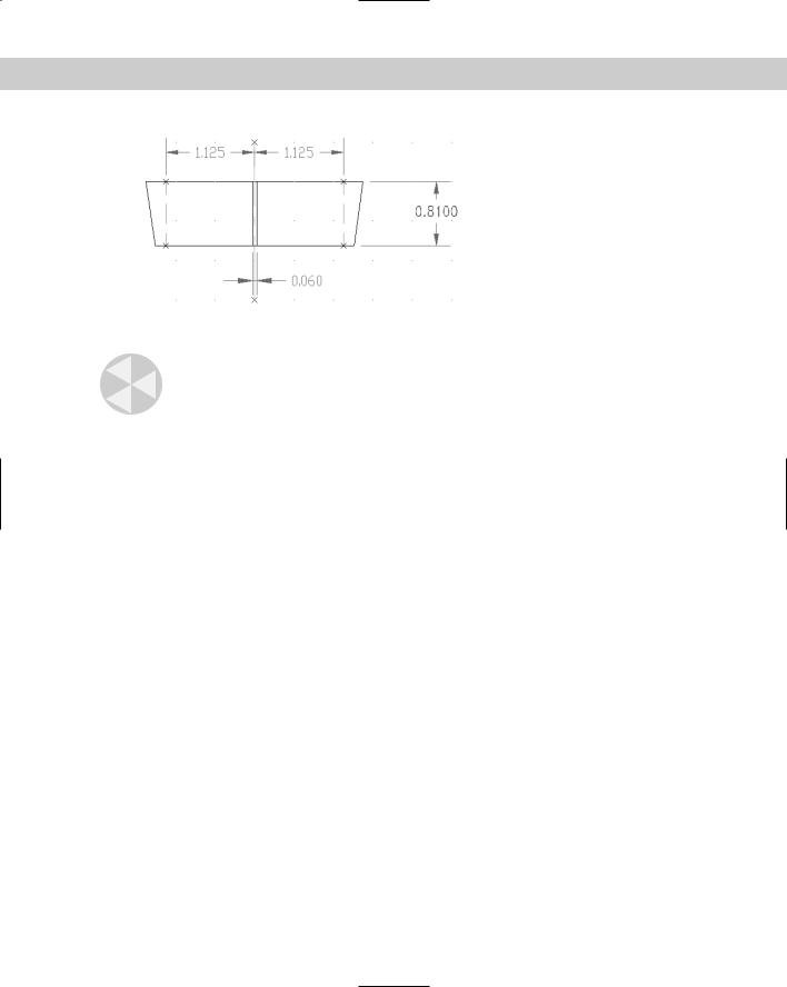
You can also use Quick Dimension to edit dimensions, whether created with QDIM or some other dimensioning command. When you select the geometry and dimensions you want to edit, you see an X at each eligible edit point, as shown in Figure 14-35.
Here’s what you can do with QDIM:
You can join two dimensions by removing the edit points between them.
You can split a dimension into two dimensions by adding edit points within the existing dimension.
You can move the dimension line.
You can change the type of dimension.
Chapter 14 Drawing Dimensions 373
Figure 14-35: When you edit with QDIM, you see an X at eligible edit points.
Caution |
Editing with QDIM works best when the geometry is simple. Unless you can select only the |
|
geometry and dimensions that you want to work with, you’ll end up changing dimensions |
|
that you don’t want to edit. |
To edit dimensions with QDIM, follow these steps:
1.Choose Quick Dimension from the Dimension toolbar.
2.At the Select geometry to dimension: prompt, select the geometry and the dimensions that you want to edit.
3.At the Specify dimension line position, or [Continuous/Staggered/ Baseline/Ordinate/Radius/Diameter/datumPoint/Edit/SeTtings] <Continuous>: prompt, right-click and choose Edit. You see a cross at each eligible edit point.
4.At the Indicate dimension point to remove, or [Add/eXit] <eXit>: prompt, you can:
•Select the points of the dimensions you want to remove. If you see two possible edit points in line with each other that could be creating the dimension you want to remove, select both of them.
•Right-click and choose Add. Use object snaps to add one or more points.
•Right-click and choose Exit to continue with the command.
5.At the Specify dimension line position, or [Continuous/Staggered/ Baseline/Ordinate/Radius/Diameter/datumPoint/Edit/SeTtings] <Continuous>: prompt, right-click and choose an option if you want to change the type of dimension.
6.The prompt repeats. Pick a location for the new set of dimensions.
7.Press Enter to end the command and update the dimensions.
Using grips to edit dimensions
Grips are ideal for moving dimension lines and text. The grips at the dimension line endpoints and the text insertion point are quite useful for making adjustments in dimensions.
374 Part II Drawing in Two Dimensions
To move a dimension line closer or farther from the dimensioned object, pick the dimension to display the grips. Pick one of the grips at the endpoints of the dimension line to highlight it. The Specify stretch point or /Base point/Copy/ Undo/eXit: prompt appears.
Drag the dimension line to the desired location. Press Esc to remove the grips.
To move dimension text, pick the dimension to display the grips. Pick the grip on the dimension text to highlight it. Drag the dimension text to its desired location.
Tip For best results, turn ORTHO on while trying to drag the dimension line or the dimension text. Polar tracking also works well.
Editing objects and dimensions together
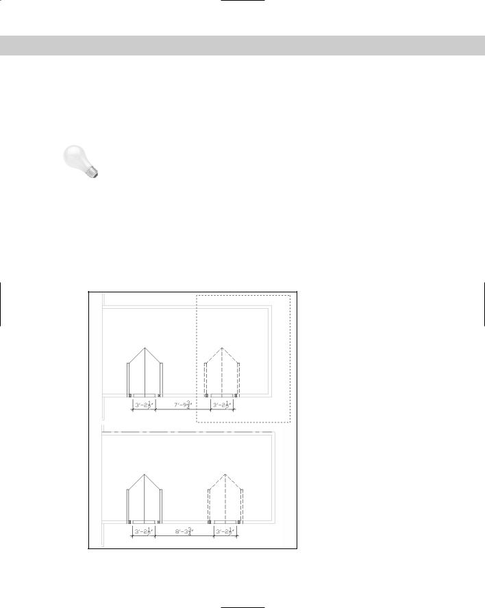
Dimension associativity enables you to edit objects and have the dimensions automatically adjust to the new object measurements. Stretching the object with the STRETCH command or grips is usually the best way to accomplish this. The object and the dimension adjust at the same time. Figure 14-36 shows a house plan before and after stretching to move a window 6 inches to the left. The crossing window included the entire window, so it was simply moved. However, the crossing window crossed the walls on either side of the window and both dimensions so that they were stretched 6 inches to the left. Notice the change in the dimension text, indicating the new measurements.
Figure 14-36: When you stretch objects, the dimensions are automatically updated.
Chapter 14 Drawing Dimensions 375
On the |
The drawing used in the following Step-by-Step exercise on using DDEDIT, QDIM, grips, and |
CD-ROM |
STRETCH to edit dimensions, ab14-h.dwg, is in the Drawings folder on the CD-ROM. |
STEP-BY-STEP: Using DDEDIT, QDIM, Grips, and STRETCH to Edit Dimensions
1.Open ab14-h.dwg from your CD-ROM.
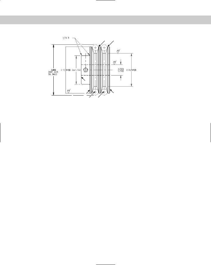
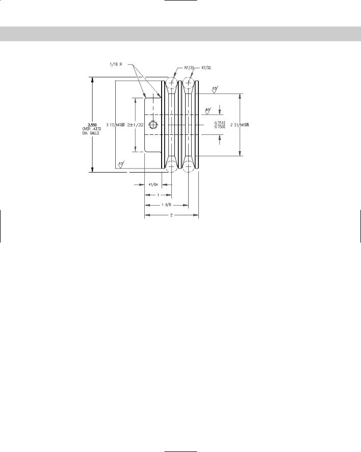
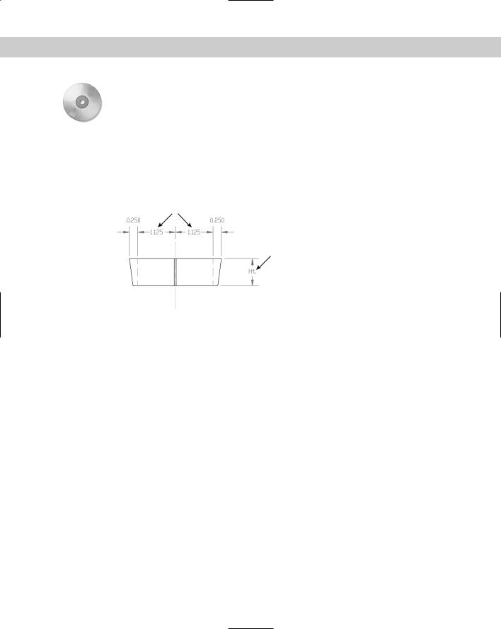
2.Save the file as ab14-09.dwg in your AutoCAD Bible folder. This is a cross-section of a valve part, as shown in Figure 14-37. Open the Dimension toolbar if it isn’t displayed.
2
1
3
4
Figure 14-37: A dimensioned cross-section of a valve part.
3.To replace the dimension marked Ht., choose Modify Object Text Edit. At the
Select an annotation object or [Undo]: prompt, choose the dimension at 1 in Figure 14-37. The Multiline Text Editor opens with the text displayed. Select the current text and type <>. Click OK. The command automatically creates the original measured dimension. Press Enter to end the command.
4.If you are using AutoCAD LT skip to Step 5. Select the two dimensions marked 2 in Figure 14-37. Also select the cyan center line and the two green hidden lines. Choose Quick Dimension from the Dimension toolbar. At the first prompt, right-click and choose Edit.
At the Indicate dimension point to remove, or [Add/eXit] <eXit>: prompt, choose the two edit points (each marked with an X) on the cyan centerline. Right-click and choose Exit. At the Specify dimension line position, or [Continuous/ Staggered/Baseline/Ordinate/Radius/Diameter/ datumPoint/Edit/SeTtings] <Continuous>: prompt, place the dimension line where it was previously. (You can use the outside arrows as a guide.)
5.Pick the dimension at 1. Click the grip on the text to activate it. Drag it to the left slightly to place it closer to the object it is dimensioning.
6.Choose Stretch from the Modify toolbar. Follow the prompts:
Select objects: Pick at 3.
Specify opposite corner: Pick at 4.
9 found
Select objects:
Specify base point or displacement: 0,–.25 Specify second point of displacement: