

- •Foreword
- •Preface
- •Is This Book for You?
- •How This Book Is Organized
- •How to Use This Book
- •Doing the Exercises
- •Conventions Used in This Book
- •What the Icons Mean
- •About the CD-ROM
- •Other Information
- •Contacting the Author
- •Acknowledgments
- •Contents at a Glance
- •Contents
- •Getting Acquainted with AutoCAD and AutoCAD LT
- •Starting AutoCAD and AutoCAD LT
- •Creating a New Drawing
- •Using the AutoCAD and AutoCAD LT Interface
- •Creating Your First Drawing
- •Saving a Drawing
- •Summary
- •Creating a New Drawing from a Template
- •Working with Templates
- •Opening a Drawing with Default Settings
- •Opening an Existing Drawing
- •Using an Existing Drawing as a Prototype
- •Saving a Drawing Under a New Name
- •Summary
- •The Command Line
- •Command Techniques
- •Of Mice and Pucks
- •Getting Help
- •Summary
- •Typing Coordinates
- •Displaying Coordinates
- •Picking Coordinates on the Screen
- •Locating Points
- •Summary
- •Unit Types
- •Drawing Limits
- •Understanding Scales
- •Inserting a Title Block
- •Common Setup Options
- •The MVSETUP Command
- •Summary
- •Using the LINE Command
- •Drawing Rectangles
- •Drawing Polygons
- •Creating Construction Lines
- •Creating Rays
- •Summary
- •Drawing Circles
- •Drawing Arcs
- •Creating Ellipses and Elliptical Arcs
- •Making Donuts
- •Placing Points
- •Summary
- •Panning
- •The ZOOM Command
- •Aerial View
- •Named Views
- •Tiled Viewports
- •Snap Rotation
- •User Coordinate Systems
- •Isometric Drawing
- •Summary
- •Editing a Drawing
- •Selecting Objects
- •Summary
- •Copying and Moving Objects
- •Using Construction Commands
- •Creating a Revision Cloud
- •Hiding Objects with a Wipeout
- •Double-Clicking to Edit Objects
- •Grips
- •Editing with the Properties Palette
- •Selection Filters
- •Groups
- •Summary
- •Working with Layers
- •Changing Object Color, Linetype, and Lineweight
- •Working with Linetype Scales
- •Importing Layers and Linetypes from Other Drawings
- •Matching Properties
- •Summary
- •Drawing-Level Information
- •Object-Level Information
- •Measurement Commands
- •AutoCAD’s Calculator
- •Summary
- •Creating Single-Line Text
- •Understanding Text Styles
- •Creating Multiline Text
- •Creating Tables
- •Inserting Fields
- •Managing Text
- •Finding Text in Your Drawing
- •Checking Your Spelling
- •Summary
- •Working with Dimensions
- •Drawing Linear Dimensions
- •Drawing Aligned Dimensions
- •Creating Baseline and Continued Dimensions
- •Dimensioning Arcs and Circles
- •Dimensioning Angles
- •Creating Ordinate Dimensions
- •Drawing Leaders
- •Using Quick Dimension
- •Editing Dimensions
- •Summary
- •Understanding Dimension Styles
- •Defining a New Dimension Style
- •Changing Dimension Styles
- •Creating Geometric Tolerances
- •Summary
- •Creating and Editing Polylines
- •Drawing and Editing Splines
- •Creating Regions
- •Creating Boundaries
- •Creating Hatches
- •Creating and Editing Multilines
- •Creating Dlines
- •Using the SKETCH Command
- •Digitizing Drawings with the TABLET Command
- •Summary
- •Preparing a Drawing for Plotting or Printing
- •Creating a Layout in Paper Space
- •Working with Plot Styles
- •Plotting a Drawing
- •Summary
- •Combining Objects into Blocks
- •Inserting Blocks and Files into Drawings
- •Managing Blocks
- •Using Windows Features
- •Working with Attributes
- •Summary
- •Understanding External References
- •Editing an Xref within Your Drawing
- •Controlling Xref Display
- •Managing Xrefs
- •Summary
- •Preparing for Database Connectivity
- •Connecting to Your Database
- •Linking Data to Drawing Objects
- •Creating Labels
- •Querying with the Query Editor
- •Working with Query Files
- •Summary
- •Working with 3D Coordinates
- •Using Elevation and Thickness
- •Working with the User Coordinate System
- •Summary
- •Working with the Standard Viewpoints
- •Using DDVPOINT
- •Working with the Tripod and Compass
- •Getting a Quick Plan View
- •Shading Your Drawing
- •Using 3D Orbit
- •Using Tiled Viewports
- •Defining a Perspective View
- •Laying Out 3D Drawings
- •Summary
- •Drawing Surfaces with 3DFACE
- •Drawing Surfaces with PFACE
- •Creating Polygon Meshes with 3DMESH
- •Drawing Standard 3D Shapes
- •Drawing a Revolved Surface
- •Drawing an Extruded Surface
- •Drawing Ruled Surfaces
- •Drawing Edge Surfaces
- •Summary
- •Drawing Standard Shapes
- •Creating Extruded Solids
- •Drawing Revolved Solids
- •Creating Complex Solids
- •Sectioning and Slicing Solids
- •Using Editing Commands in 3D
- •Editing Solids
- •Listing Solid Properties
- •Summary
- •Understanding Rendering
- •Creating Lights
- •Creating Scenes
- •Working with Materials
- •Using Backgrounds
- •Doing the Final Render
- •Summary
- •Accessing Drawing Components with the DesignCenter
- •Accessing Drawing Content with Tool Palettes
- •Setting Standards for Drawings
- •Organizing Your Drawings
- •Working with Sheet Sets
- •Maintaining Security
- •Keeping Track of Referenced Files
- •Handling Errors and Crashes
- •Managing Drawings from Prior Releases
- •Summary
- •Importing and Exporting Other File Formats
- •Working with Raster Images
- •Pasting, Linking, and Embedding Objects
- •Summary
- •Sending Drawings
- •Opening Drawings from the Web
- •Creating Object Hyperlinks
- •Publishing Drawings
- •Summary
- •Working with Customizable Files
- •Creating Keyboard Shortcuts for Commands
- •Customizing Toolbars
- •Customizing Tool Palettes
- •Summary
- •Creating Macros with Script Files
- •Creating Slide Shows
- •Creating Slide Libraries
- •Summary
- •Creating Linetypes
- •Creating Hatch Patterns
- •Summary
- •Creating Shapes
- •Creating Fonts
- •Summary
- •Working with Menu Files
- •Customizing a Menu
- •Summary
- •Introducing Visual LISP
- •Getting Help in Visual LISP
- •Working with AutoLISP Expressions
- •Using AutoLISP on the Command Line
- •Creating AutoLISP Files
- •Summary
- •Creating Variables
- •Working with AutoCAD Commands
- •Working with Lists
- •Setting Conditions
- •Managing Drawing Objects
- •Getting Input from the User
- •Putting on the Finishing Touches
- •Summary
- •Understanding Local and Global Variables
- •Working with Visual LISP ActiveX Functions
- •Debugging Code
- •Summary
- •Starting to Work with VBA
- •Writing VBA Code
- •Getting User Input
- •Creating Dialog Boxes
- •Modifying Objects
- •Debugging and Trapping Errors
- •Moving to Advanced Programming
- •A Final Word
- •Installing AutoCAD and AutoCAD LT
- •Configuring AutoCAD
- •Starting AutoCAD Your Way
- •Configuring a Plotter
- •System Requirements
- •Using the CD with Microsoft Windows
- •What’s on the CD
- •Troubleshooting
- •Index

338 Part II Drawing in Two Dimensions
1.Find Word’s custom dictionary. If necessary, choose Start Find and use the Windows Find dialog box to find the file. It is called custom.dic. You can open this file with Notepad and edit it directly.
2.As explained in the previous Tip, find the location of sample.cus. Use Windows Explorer to copy the file to that folder. You can hold down Ctrl as you drag it from one folder to another or use the right mouse button to click the file, choose Copy, and then paste it in its new location.
3.Click custom.dic to highlight it. Click it again and change its filename extension to
.cus. Press Enter. (Windows asks you if you are sure you want to do this. Click Yes.)
4.Click Change Dictionaries in the Check Spelling dialog box to open the Change Dictionaries dialog box. In the Custom Dictionary text box, type in the name of the dictionary file, or choose Browse, find it, and click Open.
5.Click Apply & Close to return to the Check Spelling dialog box. Then click Cancel to return to your drawing.
Summary
In this chapter, you learned how to create, edit, and manage text. You read about:
Using DTEXT and TEXT to create single-line text
Editing single-line text
Scaling and justifying text without moving it
Creating text styles to control the formatting of your text
Utilizing MTEXT for creating and editing paragraph text, including using the Multiline Text Editor
Importing text
Managing text for the fastest display
Finding and replacing text and how to check spelling in your drawing
In the next chapter, you read about how to create dimensions.
|
|
|

Drawing
Dimensions
Dimensions are an important part of most drawings. Dimensions indicate the measurement of the models you’ve created and are used in the manufacturing process. The dimensions in AutoCAD and AutoCAD LT offer a great deal of flexibility. In this chapter, I cover the process of drawing dimensions. In the next chapter, I explain how to customize the format of your dimensions by using dimension styles.
Working with Dimensions
Dimensioning is usually done after you complete all or most of a drawing. Dimensioning a drawing all at once lets you create a unified, organized look for your dimensions. Before you can dimension a drawing, you need to understand the elements of a dimension and how to prepare for dimensioning.
Cross- |
In Chapter 17, I explain how to dimension a drawing on a paper |
|
space layout. |
||
Reference |
The elements of a dimension
A dimension is a complex object, containing many parts. Understanding these parts and how they relate to the object you’re dimensioning is an important first step. Figure 14-1 shows a typical linear dimension.
The parts of a dimension are:
Extension lines: These extend from the dimensioned object to the dimension line and arrowheads. A small gap usually separates the dimensioned object and the start of the extension lines. Extension lines visually clarify the extents of the object being dimensioned.
Note In dimensions, the word extension (or extend) is used in two other ways besides referring to extension lines. First, the extension line itself usually extends not only from the object being dimensioned but past the dimension line. You can specify the amount of this extension. Also, in architectural dimensions, the dimension line extends past the extension lines. You can specify this extension as well.
14C H A P T E R
In This Chapter
Working with dimensions
Drawing linear and aligned dimensions
Dimensioning arcs, circles, and angles
Creating ordinate dimensions
Drawing leaders
Editing dimensions
340 Part II Drawing in Two Dimensions
Arrowhead |
Dimension text |
Dimension line |
 Extension line
Line object
Figure 14-1: The parts of a dimension.
Dimension text: This tells you the actual measurement of the dimensioned object. You can format this text in decimals, fractions, scientific units, and so on.
Dimension line: This extends between the extension lines.
Arrowheads: These mark the intersection of the dimension line and the extension lines. They can take several forms, such as tick marks, open arrows, or dots.
Dimensions have two interesting properties that you need to understand before you can successfully work with them.
Dimensions are blocks. I have mentioned blocks earlier in this book, and they are fully covered in Chapter 18. Blocks are groups of objects that you can manipulate as one object. As a result, if you pick a dimension, all parts of the dimension are selected.
Dimensions are associative. This means that an association connects the dimension and the object it dimensions. If you change the size of the object, the dimension automatically adjusts appropriately.
All the parts of a dimension can be formatted individually. You generally format a dimension by creating a dimension style, which is a named set of formats for dimensions — just as a text style is a named set of formats for text. (Dimension styles are the topic of the next chapter.)
Preparing to dimension
Dimensioning requires some preparation so that the result will be what you want. Before starting to create dimensions, you should prepare as follows:
1.Create a layer for your dimensions. It’s important that dimensions be easily distinguishable from the rest of your drawing. The color is usually a contrast to that of your models. For example, if your models are black (and you’re working on a white screen), you might want your dimensions to be green, magenta, or cyan.
Tip |
If you often turn layers on and off (or freeze and thaw them), you may want to create a sep- |
|
arate dimension layer for each layer of drawing data. For example, if you dimension an elec- |
|
trical layer that you turn off regularly, you can have a special Dim-elec dimension layer that |
|
you can turn off with the electrical layer. |
Chapter 14 Drawing Dimensions 341
2.If you’re dimensioning an existing drawing that was created in a pre-2002 version of
AutoCAD or AutoCAD LT, turn on associative dimensioning with the DIMASSOC system variable. Type dimassoc on the command line and type 2 at the prompt. (You can also choose Tools Options, click the User Preferences tab, and check the check box in the Associative Dimensioning section of the dialog box. Then click OK.)
3.Create a text style for your dimensions.
Tip |
Set the height of the text style to zero. You can then set the text height when you create the |
|
dimension style. If you do specify a fixed height in your text style, that height overrides any |
|
height you specify in the dimension style. |
4.Choose Tools Drafting Settings, click the Object Snap tab, and set the running object snaps you want. Endpoint and intersection are a necessity. Add center and quadrant if you need to dimension arcs and circles. Click OSNAP on the status bar to turn it on.
5.Create a dimension style. The next chapter covers dimension styles.
6.Save your dimension layer, dimension text style, and dimension style in your drawing templates.
The Dimension toolbar makes it easy to find the dimension commands quickly. The Dimension menu offers most of the same commands as the toolbar. To display the Dimension toolbar, right-click any toolbar and check Dimension from the list.
Drawing Linear Dimensions
Just as the most common objects are lines, the most common dimensions are linear dimensions. Use linear dimensions for lines, a straight segment of a polyline, or a straight segment in a block. You can also use a linear dimension for arcs and circles — you get the linear length of the arc (not its perimeter length) and the diameter of the circle.
|
Specifying the dimensioned object |
|
To dimension a line, choose Linear Dimension from the Dimension toolbar. The com- |
|
mand responds with the Specify first extension line origin or <select |
|
object>: prompt. You can now either pick two extension line origin points or press Enter |
|
and select an object for dimensioning. |
Tip |
Make it standard practice to use object snaps for choosing extension line origins. The point |
|
you pick specifies the definition point that determines the final measurement. Also, proper |
|
association of dimensions with their objects depends on the points you specify. Accurate |
|
dimensioning requires accurate drawings and, therefore, exact specification of the points you |
|
want to use for the dimensions. |
|
If you’re dimensioning more than one object, such as the distance from the endpoint of one |
|
line to the endpoint of another line, pick the first extension line origin. At the Specify second |
|
extension line origin: prompt, pick the second extension line origin. These two points |
|
define the length of the dimension. |
|
If you’re dimensioning one object, press Enter at the Specify first extension line ori- |
|
gin or <select object>: prompt. The Select object to dimension: prompt appears. |
|
Pick the object. |
342 Part II Drawing in Two Dimensions
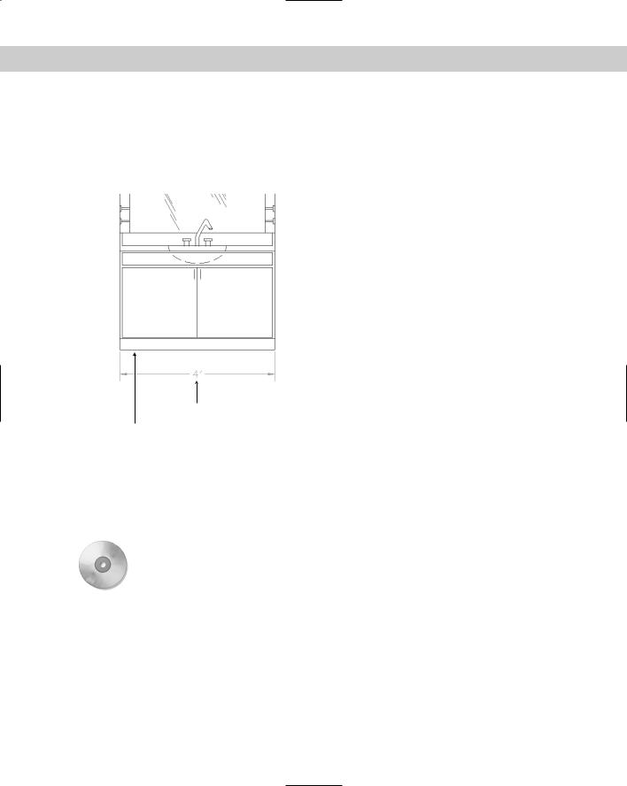
At the Specify dimension line location or [Mtext/Text/Angle/Horizontal/ Vertical/Rotated]: prompt, pick a point for the location of the dimension line. As you move the mouse, you can see the results on your screen, as shown in Figure 14-2. If you want an exact location, you can type in a relative coordinate, such as @0,.5 to specify that the dimension line should be 0.5 units above the object. Snap mode may also work well for you, depending on the drawing environment.
Figure 14-2: Picking a dimension line location for a linear dimension.
Pick point
Dimensioned object
Object snap tracking makes it a snap to pick points for dimensioning. For example, if you’re dimensioning a house, your first extension line origin may be the outside corner of the house, but the second extension line origin may be an inner wall. At the Specify first extension line origin or <select object>: prompt, move the cursor over the inner wall endpoint to acquire it. Move the cursor back to the line you’re dimensioning and click when you see the tooltip showing the snap point you chose. The dimension goes just where you need it.
On the |
The drawing used in the following Step-by-Step exercise on drawing linear dimensions, |
CD-ROM |
ab14-a.dwg, is in the Drawings folder on the CD-ROM. |
STEP-BY-STEP: Drawing Linear Dimensions
1.Open ab14-a.dwg from your CD-ROM.
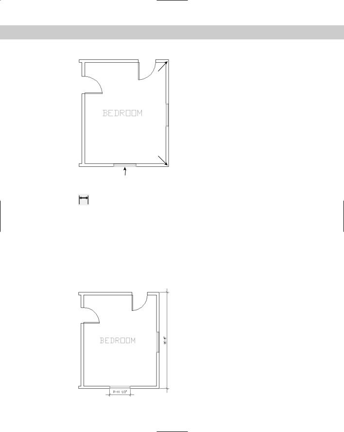
2.Save the file as ab14-01.dwg in your AutoCAD Bible folder. This is a plan of a bedroom, as shown in Figure 14-3. ORTHO and OSNAP should be on. Set running object snaps for endpoint, midpoint, and intersection. The current layer should be set to Dim.
3.To display the Dimension toolbar, right-click any toolbar. Click Dimension. If you want, drag the toolbar to the top or bottom of your screen until it docks.
Chapter 14 Drawing Dimensions 343
Figure 14-3: A bedroom plan.
2
1
3
4.Choose Linear Dimension from the Dimension toolbar. At the Specify first
extension line origin or <select object>: prompt, pick 1 in Figure 14-3. At the Specify second extension line origin: prompt, pick 2. At the Specify dimension line location or [Mtext/Text/Angle/Horizontal/Vertical/ Rotated]: prompt, move the cursor to the right until you have sufficient space for the dimension text and click.
5.Repeat the DIMLINEAR command. At the Specify first extension line origin or <select object>: prompt, press Enter. At the Select object to dimension: prompt, pick 3 (the window) in Figure 14-3. At the Specify dimension line location or [Mtext/Text/Angle/Horizontal/Vertical/ Rotated]: prompt, move the cursor down until you have sufficient space for the dimension text and click.
6.Save your drawing. It should look like Figure 14-4.
Figure 14-4: The bedroom with two linear dimensions.
344 Part II Drawing in Two Dimensions
Using dimension options
You can also use one of the options offered at the command prompt to further control the final dimension. Dimension options control the text and the angle of the dimension.
MText
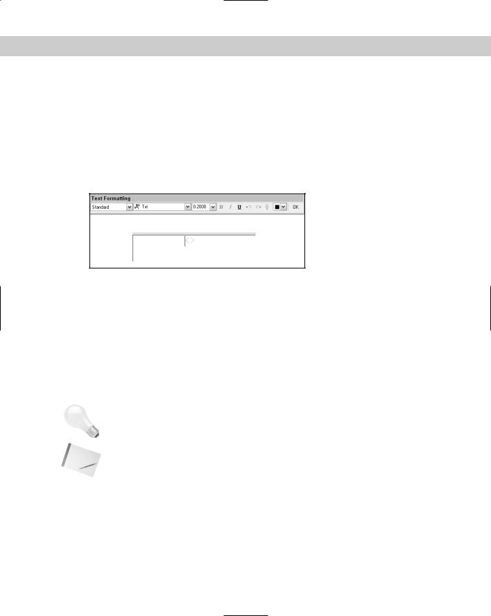
The MText option lets you replace the calculated dimension text or add a prefix or suffix to it. When you right-click and choose MText at the Specify dimension line location or [Mtext/Text/Angle/Horizontal/Vertical/Rotated]: prompt, the Multiline Text Editor opens, as shown in Figure 14-5.
Figure 14-5: Changing the dimension text with the Multiline
Text Editor.
The angle brackets represent the automatic dimension text. The best use of the MText option is to add some text before or after the measurement, such as TYP (for typical — used when one dimension applies to several objects) or subject to final approval. To add text before the measurement, place the cursor before the angle brackets. Similarly, to add text after the measurement, place the cursor after the angle brackets. Add the text and click OK.
If the measurement text itself does not appear the way you want it, you should change the annotation specifications in the dimension style. You can also specify a prefix or suffix (such as mm) for all dimensions, as explained in the next chapter. You can delete the brackets and type your own dimension text, but you lose the ability of the dimension’s measurement to automatically adjust to any change in the object’s size.
Tip |
To add text below the dimension line, enter \X after the dimension text. Any text after the \X |
|
goes below the dimension line. |
Note |
Typing your own dimension text is most commonly used where a dimension represents sev- |
|
eral sizes and refers to a size chart elsewhere in the drawing. For example, the text “Dim A” |
|
might be used for this purpose. |
Text
The Text option also lets you change dimension text but does not open the Multiline Text Editor. Instead, you can quickly retype the entire dimension text as you want it on the command line.
Chapter 14 Drawing Dimensions 345
Angle
The angle of the text (horizontal, vertical, or aligned) is specified in your dimension style. However, you can use this option to change the angle of the dimension text for a particular circumstance. Right-click and choose Angle to get the Specify angle of dimension text: prompt. Type in an angle or pick two points to align the text with an existing object.
Horizontal/vertical
The DIMLINEAR command assumes that you want a horizontal dimension if you select a horizontal object or two definition points running horizontally — ditto for a vertical dimension. Also, if you want to draw a vertical dimension of an object at an angle, you can specify this simply by moving the mouse cursor horizontally when specifying the dimension line location, as shown in Figure 14-6. If for some reason you need to force either a horizontal or vertical dimension, you can use the vertical or horizontal options.
Figure 14-6: By dragging the mouse cursor to the right, you can create a vertical dimension for this angled line. The vertical dimension measures the change in the
Y coordinates of the line, not the length of the line.
Rotated
Use a rotated linear dimension when the length you want to dimension is not parallel to the extension line origins. Just as the vertical dimension in Figure 14-6 does not measure the length of the line its extension lines extend to, a rotated linear dimension does not measure a specific object but the distance of an imaginary line parallel to the dimension line. Rotated dimensions are not very common, but when you need them they’re the only way to get the dimension measurement you need.
To use a rotated dimension, start a linear dimension, pick the two extension line origins and choose the Rotate option. At the Specify angle of dimension line <0>: prompt, type the angle (or pick two points) to draw the dimension.