102 Part II Drawing in Two Dimensions
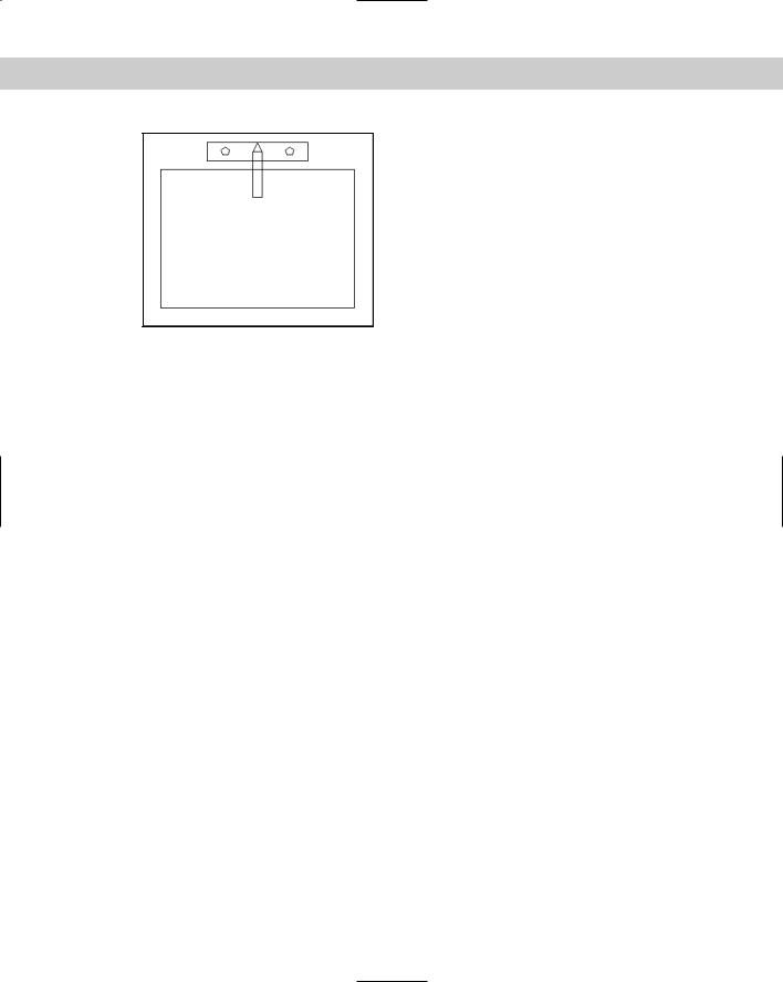
Figure 6-3: The completed sink, drawn with rectangles and polygons.
Thanks to Bill Wynn of New Windsor, Maryland, for this drawing, which he created in his AutoCAD class as part of a plan drawing of an entire house.
Creating Construction Lines
Sometimes you want to create a line that is used solely for the purpose of reference. For example, you might want to do the following:
Draw two lines from the midpoints of two perpendicular lines so that you can use their intersection as the center for a circle.
Draw a line from one object to another to visually indicate the relationship between the two objects.
Show the relationship between equivalent parts of a model shown in front and right-side views.
Draw a line through the center of an object shown in cross-section so that you can show dimensions from the centerline to the edge of an object.
You could use regular lines for these purposes. However, construction lines (also known as xlines) are unique in that they extend infinitely in both directions. This makes them especially useful for seeing the relationships among various objects in your drawing.
Of course, construction lines are not actually infinite. However, they extend to the edge of the drawing area on your screen, and if you zoom out to see more of your drawing, they expand so that they always extend to the edge of the screen. The object snap tracking feature sometimes eliminates the need for construction lines; nevertheless, sometimes you can work more easily having a line visible for several commands and then erasing it.
If you zoom to show the extents of your drawing, AutoCAD or AutoCAD LT ignores the xlines and shows you just the extents of the regular objects in your drawing. Chapter 8 covers the ZOOM command.
Chapter 6 Drawing Simple Lines 103
Cross- |
Construction lines are also helpful when working in 3D. See Part IV of this book. |
Reference |
|
The XLINE command offers several ways to create construction lines. Start the command by choosing Construction Line from the Draw toolbar. You see the following
prompt:
Specify a point or [Hor/Ver/Ang/Bisect/Offset]:
Table 6-2 lists the possible options. AutoCAD or AutoCAD LT continues to prompt you for more points so that you can continue to draw construction lines — much like the LINE command. Press Enter to end the command.
|
Table 6-2: XLINE Command Options |
|
|
Option |
Description |
|
|
Specify a point |
This option enables you to define the construction line with two points. At the first |
|
prompt, specify a point. At the Specify through point: prompt, specify another |
|
point. The first point becomes the base point for subsequent construction lines that |
|
you can draw by specifying other through points. |
Hor |
To draw a construction line parallel to the X axis, type h to specify the Horizontal |
|
option. The command responds with the Specify through point: prompt. |
|
Specify one point. Useful for drawing a series of horizontal construction lines. |
Ver |
To draw a construction line parallel to the Y axis, type v to specify the Vertical option. |
|
The command responds with the Specify through point: prompt. Specify one |
|
point. |
Ang |
Type a (for Angle). The command responds with the Enter angle of xline |
|
(0) or [Reference]: prompt. If you enter an angle, the command asks for a |
|
through point. Or you can type r and select a line as a reference, then provide an |
|
angle and a through point. AutoCAD or AutoCAD LT then calculates the angle of the |
|
construction line from the angle of the reference line. Useful for drawing a series of |
|
construction lines at a specified angle. |
Bisect |
To draw a construction line that bisects an angle (divides the angle in half), type b . |
|
The command responds with the Specify angle vertex point: prompt. |
|
Choose any point that you want the construction line to pass through. Then, at the |
|
Specify angle start point: prompt, choose a point that defines the base of |
|
the angle. At the Specify angle end point: prompt, choose a point that |
|
defines the end of the angle. |
Offset |
To draw a construction line parallel to a line, type o . You can specify the offset |
|
distance by typing in the number or using the Through option to pick a point through |
|
which the construction line should pass. Either way, the next step is to select a line. If |
|
you specified an offset distance, the command displays the Specify side to |
|
offset: prompt. Respond by picking a point on the side of the selected line on |
|
which you want the construction line to appear. |
|
|
104 Part II Drawing in Two Dimensions
Creating Rays
Rays are similar to construction lines, except that they start at a specific point and extend to infinity in one direction only. If you need a line to extend only in one direction, using a ray may be less confusing.
Tip |
You can use most object snaps with construction lines and rays. (You can’t use endpoint for |
|
construction lines or midpoint for rays.) Construction lines and rays can be edited like any |
|
other object. |
To draw a ray, choose Draw Ray. At the Specify start point: prompt, specify the start point for the ray. At the Specify through point: prompt, specify another point. AutoCAD or AutoCAD LT continues to ask for through points. Press Enter to end the command.
On the |
The drawing used in this Step-by-Step exercise on drawing construction lines and rays, |
CD-ROM |
ab06-b.dwg, is in the Drawings folder on the CD-ROM. |
STEP-BY-STEP: Drawing Construction Lines and Rays
1.Open ab06-b.dwg from the CD-ROM.
2.Save the drawing as ab06-03.dwg in your AutoCAD Bible folder.
3. Choose Construction Line from the Draw toolbar.
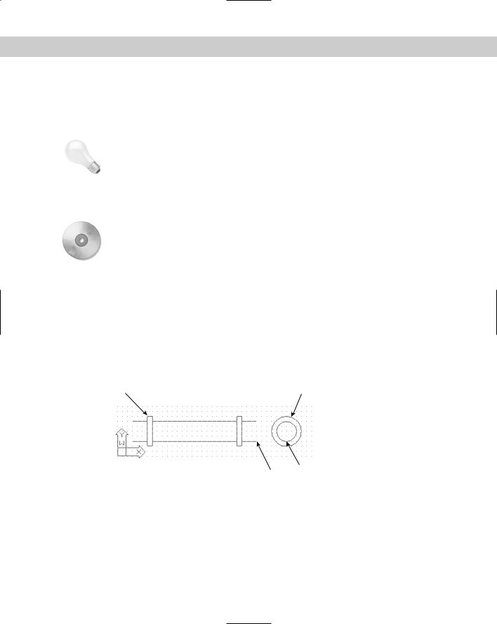
4.At the Specify a point or [Hor/Ver/Ang/Bisect/Offset]: prompt, choose point 1, shown in Figure 6-4.
5.At the Specify through point: prompt, choose point 2, shown in Figure 6-4.
2 |
1 |
4
3
Figure 6-4: A pipe with cross-section.
6.Press Enter to end the command. Notice that the drawing has been set up so that the construction line is drawn in green and with a noncontinuous linetype. This is to distinguish it from the main drawing. (See Chapter 11 for details on how to set up a drawing in this way.)

Chapter 6 Drawing Simple Lines 105
7.Choose Draw Ray.
8.At the Specify start point: prompt, choose point 3, shown in Figure 6-4.
9.At the Specify through point: prompt, choose point 4, shown in Figure 6-4. Press Enter to end the command.
10.Save your drawing.
Summary
This chapter covered the ins and outs of lines. You read about:
Using the LINE command
Drawing rectangles
Drawing polygons
Creating construction lines, including xlines that extend infinitely in both directions and rays that extend infinitely in one direction
The next chapter explains how to draw curves and point objects. Curves include circles, arcs, ellipses, and donuts.
|
|
|