

- •Foreword
- •Preface
- •Is This Book for You?
- •How This Book Is Organized
- •How to Use This Book
- •Doing the Exercises
- •Conventions Used in This Book
- •What the Icons Mean
- •About the CD-ROM
- •Other Information
- •Contacting the Author
- •Acknowledgments
- •Contents at a Glance
- •Contents
- •Getting Acquainted with AutoCAD and AutoCAD LT
- •Starting AutoCAD and AutoCAD LT
- •Creating a New Drawing
- •Using the AutoCAD and AutoCAD LT Interface
- •Creating Your First Drawing
- •Saving a Drawing
- •Summary
- •Creating a New Drawing from a Template
- •Working with Templates
- •Opening a Drawing with Default Settings
- •Opening an Existing Drawing
- •Using an Existing Drawing as a Prototype
- •Saving a Drawing Under a New Name
- •Summary
- •The Command Line
- •Command Techniques
- •Of Mice and Pucks
- •Getting Help
- •Summary
- •Typing Coordinates
- •Displaying Coordinates
- •Picking Coordinates on the Screen
- •Locating Points
- •Summary
- •Unit Types
- •Drawing Limits
- •Understanding Scales
- •Inserting a Title Block
- •Common Setup Options
- •The MVSETUP Command
- •Summary
- •Using the LINE Command
- •Drawing Rectangles
- •Drawing Polygons
- •Creating Construction Lines
- •Creating Rays
- •Summary
- •Drawing Circles
- •Drawing Arcs
- •Creating Ellipses and Elliptical Arcs
- •Making Donuts
- •Placing Points
- •Summary
- •Panning
- •The ZOOM Command
- •Aerial View
- •Named Views
- •Tiled Viewports
- •Snap Rotation
- •User Coordinate Systems
- •Isometric Drawing
- •Summary
- •Editing a Drawing
- •Selecting Objects
- •Summary
- •Copying and Moving Objects
- •Using Construction Commands
- •Creating a Revision Cloud
- •Hiding Objects with a Wipeout
- •Double-Clicking to Edit Objects
- •Grips
- •Editing with the Properties Palette
- •Selection Filters
- •Groups
- •Summary
- •Working with Layers
- •Changing Object Color, Linetype, and Lineweight
- •Working with Linetype Scales
- •Importing Layers and Linetypes from Other Drawings
- •Matching Properties
- •Summary
- •Drawing-Level Information
- •Object-Level Information
- •Measurement Commands
- •AutoCAD’s Calculator
- •Summary
- •Creating Single-Line Text
- •Understanding Text Styles
- •Creating Multiline Text
- •Creating Tables
- •Inserting Fields
- •Managing Text
- •Finding Text in Your Drawing
- •Checking Your Spelling
- •Summary
- •Working with Dimensions
- •Drawing Linear Dimensions
- •Drawing Aligned Dimensions
- •Creating Baseline and Continued Dimensions
- •Dimensioning Arcs and Circles
- •Dimensioning Angles
- •Creating Ordinate Dimensions
- •Drawing Leaders
- •Using Quick Dimension
- •Editing Dimensions
- •Summary
- •Understanding Dimension Styles
- •Defining a New Dimension Style
- •Changing Dimension Styles
- •Creating Geometric Tolerances
- •Summary
- •Creating and Editing Polylines
- •Drawing and Editing Splines
- •Creating Regions
- •Creating Boundaries
- •Creating Hatches
- •Creating and Editing Multilines
- •Creating Dlines
- •Using the SKETCH Command
- •Digitizing Drawings with the TABLET Command
- •Summary
- •Preparing a Drawing for Plotting or Printing
- •Creating a Layout in Paper Space
- •Working with Plot Styles
- •Plotting a Drawing
- •Summary
- •Combining Objects into Blocks
- •Inserting Blocks and Files into Drawings
- •Managing Blocks
- •Using Windows Features
- •Working with Attributes
- •Summary
- •Understanding External References
- •Editing an Xref within Your Drawing
- •Controlling Xref Display
- •Managing Xrefs
- •Summary
- •Preparing for Database Connectivity
- •Connecting to Your Database
- •Linking Data to Drawing Objects
- •Creating Labels
- •Querying with the Query Editor
- •Working with Query Files
- •Summary
- •Working with 3D Coordinates
- •Using Elevation and Thickness
- •Working with the User Coordinate System
- •Summary
- •Working with the Standard Viewpoints
- •Using DDVPOINT
- •Working with the Tripod and Compass
- •Getting a Quick Plan View
- •Shading Your Drawing
- •Using 3D Orbit
- •Using Tiled Viewports
- •Defining a Perspective View
- •Laying Out 3D Drawings
- •Summary
- •Drawing Surfaces with 3DFACE
- •Drawing Surfaces with PFACE
- •Creating Polygon Meshes with 3DMESH
- •Drawing Standard 3D Shapes
- •Drawing a Revolved Surface
- •Drawing an Extruded Surface
- •Drawing Ruled Surfaces
- •Drawing Edge Surfaces
- •Summary
- •Drawing Standard Shapes
- •Creating Extruded Solids
- •Drawing Revolved Solids
- •Creating Complex Solids
- •Sectioning and Slicing Solids
- •Using Editing Commands in 3D
- •Editing Solids
- •Listing Solid Properties
- •Summary
- •Understanding Rendering
- •Creating Lights
- •Creating Scenes
- •Working with Materials
- •Using Backgrounds
- •Doing the Final Render
- •Summary
- •Accessing Drawing Components with the DesignCenter
- •Accessing Drawing Content with Tool Palettes
- •Setting Standards for Drawings
- •Organizing Your Drawings
- •Working with Sheet Sets
- •Maintaining Security
- •Keeping Track of Referenced Files
- •Handling Errors and Crashes
- •Managing Drawings from Prior Releases
- •Summary
- •Importing and Exporting Other File Formats
- •Working with Raster Images
- •Pasting, Linking, and Embedding Objects
- •Summary
- •Sending Drawings
- •Opening Drawings from the Web
- •Creating Object Hyperlinks
- •Publishing Drawings
- •Summary
- •Working with Customizable Files
- •Creating Keyboard Shortcuts for Commands
- •Customizing Toolbars
- •Customizing Tool Palettes
- •Summary
- •Creating Macros with Script Files
- •Creating Slide Shows
- •Creating Slide Libraries
- •Summary
- •Creating Linetypes
- •Creating Hatch Patterns
- •Summary
- •Creating Shapes
- •Creating Fonts
- •Summary
- •Working with Menu Files
- •Customizing a Menu
- •Summary
- •Introducing Visual LISP
- •Getting Help in Visual LISP
- •Working with AutoLISP Expressions
- •Using AutoLISP on the Command Line
- •Creating AutoLISP Files
- •Summary
- •Creating Variables
- •Working with AutoCAD Commands
- •Working with Lists
- •Setting Conditions
- •Managing Drawing Objects
- •Getting Input from the User
- •Putting on the Finishing Touches
- •Summary
- •Understanding Local and Global Variables
- •Working with Visual LISP ActiveX Functions
- •Debugging Code
- •Summary
- •Starting to Work with VBA
- •Writing VBA Code
- •Getting User Input
- •Creating Dialog Boxes
- •Modifying Objects
- •Debugging and Trapping Errors
- •Moving to Advanced Programming
- •A Final Word
- •Installing AutoCAD and AutoCAD LT
- •Configuring AutoCAD
- •Starting AutoCAD Your Way
- •Configuring a Plotter
- •System Requirements
- •Using the CD with Microsoft Windows
- •What’s on the CD
- •Troubleshooting
- •Index

1062 Part VII Programming AutoCAD
Keywords: Keywords are words that have a special meaning in VBA. They are often used as parts of VBA statements. For example Else is a keyword that is used in the If...Then...Else statement. You’re already familiar with the Set keyword, which is used in the Set statement.
Operators: VBA includes all the usual arithmetic operations, such as +, –, *, /, and ^. You can also use & to concatenate text strings. There are several logical operators, such as and, not, and or.
Statements: Statements help you create the flow of your code. You’re already familiar with the Set statement. Other statements are For Each...Next and If...Then...Else. These provide looping capabilities in VBA.
Remember that you can also get a list of objects and their properties and methods from the Object Browser, as explained earlier in this chapter.
Getting User Input
The examples used in this chapter weren’t very useful, partly because the routines provided no way to get user input for the properties of the objects they drew. There are two main ways to get user input — on the command line and via a dialog box. In this section, I explain how to get user input on the command line.
In order to use the user-input methods, you need to first use something called the Utility object. The Utility object belongs to the Document object and controls the methods that get user input. You can also use ThisDrawing, as in the following example.
Dim iReturn as Integer
iReturn = ThisDrawing.Utility.GetInteger(“Enter an integer: “)
Here you set a variable called iReturn equal to the integer that the user types on the command line. The prompt is Enter an integer:.
You can use this type of user input to get a pick point, a numeric value (such as the radius of a circle), a text string, or an object. Use this method when the input is short and sweet.
To avoid several prompts appearing on the same line, use vbCrLf, the carriage return/linefeed constant, at the beginning of a prompt, as in the following example:
prompt1 = vbCrLf & “Specify center point: “
Here’s an example that illustrates how to get user input on the command line:
Sub AddCircle()
Dim thePt As Variant
Dim theRadius As Double
Dim myCircle As AcadCircle
thePt = ThisDrawing.Utility.GetPoint(, vbCrLf & “Enter Center Point:”)
theRadius = ThisDrawing.Utility.GetReal(“Enter radius: “)
Set myCircle = ThisDrawing.ModelSpace.AddCircle(thePt, theRadius) End Sub
Table 37-3 lists some commonly used methods for getting user input. If you know the GET functions in AutoLISP, you’ll be familiar with these methods.

Chapter 37 Programming with Visual Basic for Applications 1063
Table 37-3: Common User-Input Methods
Method |
Syntax |
Description |
|
|
|
GetEntity |
object.GetEntity Object, |
The user selects an object (entity) by picking it. |
|
PickedPoint, Prompt |
Returns the object in the first parameter and the |
|
|
point picked in the second parameter. The |
|
|
prompt is optional. Example: ThisDrawing. |
|
|
utility.GetEntity getObj, basePnt, |
|
|
“Select an object” where getObj has |
|
|
been declared as an Object type variable. |
GetInteger |
RetVal = GetInteger (Prompt) |
Any integer from –32,768 to +32,767 is valid. |
|
|
The prompt is optional. Example: getInt = |
|
|
ThisDrawing.utility.GetInteger |
|
|
(“Enter an integer:“) |
GetPoint |
RetVal = GetPoint (Point, Prompt) |
Returns a variant (which contains a three- |
|
|
element array of doubles). The user can pick |
|
|
a point or type in a coordinate. If the Point |
|
|
parameter (optional) is provided, AutoCAD draws |
|
|
a rubberband line from Point to the current |
|
|
crosshair position. The prompt is also optional. |
|
|
Example: getPnt = ThisDrawing. utility. |
|
|
GetPoint(, “Specify a point:“) |
GetReal |
RetVal = GetReal (Prompt) |
Gets any real (positive or negative) number. The |
|
|
prompt is optional. Example: getaReal = |
|
|
ThisDrawing.utility.GetReal(“Enter a |
|
|
real number:“) |
GetString |
RetVal = GetString |
The HasSpaces parameter specifies whether the |
|
(HasSpaces, Prompt) |
string can contain spaces. If the HasSpaces |
|
|
parameter is TRUE, the string can contain blanks |
|
|
and the user must press Enter to end input. If |
|
|
HasSpaces is FALSE, entering either a blank |
|
|
or Enter ends input. The prompt is optional. |
|
|
Example: getaString = ThisDrawing. |
|
|
utility. GetString(False, “Enter |
|
|
text (a space or <enter> terminates |
|
|
input):”) |
|
|
|
STEP-BY-STEP: Creating a VBA Routine That Gets User Input
1.Open a new AutoCAD drawing using the acad.dwt template.
2.To start a new project, choose Tools Macro VBA Manager. Click New and then click Visual Basic Editor.
3.Choose Insert Module and then choose Insert Procedure. Name it HappyFace and click OK.

1064 Part VII Programming AutoCAD
4. At the cursor, type the following:
Dim prompt |
As String, prompt2 As String |
|
Dim cen As Variant |
|
|
Dim rad As Double |
|
|
Dim cir As AcadCircle |
|
|
Dim arc As AcadArc |
|
|
Dim pi As Double |
|
|
Dim dStart As Double |
‘start angle |
|
Dim dEnd As Double |
‘end angle |
|
pi = 3.1415
prompt = vbCrLf & “Specify center point: “ prompt2 = vbCrLf & “Specify radius: “
‘get center point from user
cen = ThisDrawing.Utility.GetPoint(, prompt)
rad = ThisDrawing.Utility.GetDistance(cen, prompt2)
‘draw head
Set cir = ThisDrawing.ModelSpace.AddCircle(cen, rad) ‘draw smile
dStart = 225 * pi / 180 ‘pi / 180 converts to radians DEnd = 315 * pi / 180
Set arc = ThisDrawing.ModelSpace.AddArc(cen, rad / 2, dStart, dEnd) ‘draw eyes
cen(0) = cen(0) - rad / 4 cen(1) = cen(1) + rad / 4
Set cir = ThisDrawing.ModelSpace.AddCircle(cen, rad / 8) cen(0) = cen(0) + rad / 2
Set cir = ThisDrawing.ModelSpace.AddCircle(cen, rad / 8)
5.Change the module name to HappyFace.
6.Choose Save from the VBA IDE Standard toolbar and save the VBA project as ab37-02. dvb in your AutoCAD Bible folder.
7.Return to your drawing and choose Tools Macro Macros. In the Macro dialog box, choose HappyFace and click Run.
8.Respond to the prompts. HappyFace draws the circle with the center point and radius you specify.
You don’t need to save your drawing.
The previous example uses GetDistance rather than GetReal to enable the user to select the radius of the circle with the mouse. The center point you previously selected feeds into the GetDistance function. Also, there are calculations to convert degrees to radians. The location and size of the eyes and smile are relative to the center and radius.
Chapter 37 Programming with Visual Basic for Applications 1065
Creating Dialog Boxes
One of the main characteristics of VBA is the ease with which you can create dialog boxes to get user input. Whenever you need input that is more complex than you can get using the Get methods, you should use a dialog box. You can also use a dialog box to create a more professional look or for ease of use.
When working with a dialog box, you generally create the dialog box first and then attach code to the dialog box buttons. You then use a second module to display the dialog box. Running the second module then controls the entire routine.
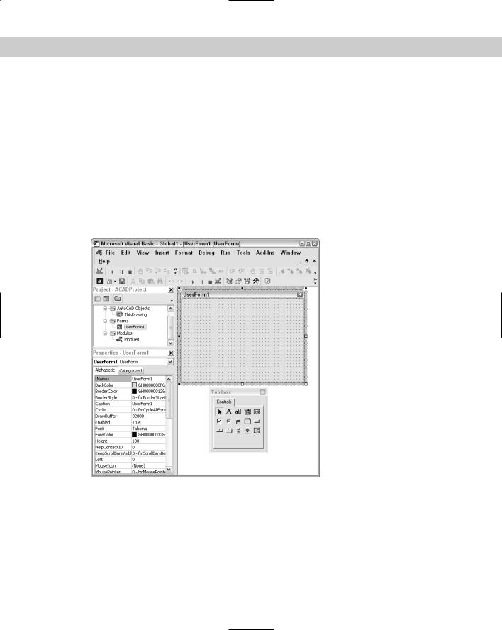
In VBA, a dialog box is called a user form. To create one, choose Insert UserForm. VBA creates a blank user form that will become your dialog box. Simultaneously, the Toolbox toolbar appears. If this toolbar covers up some other part of your screen, drag it to one side. Your screen looks like Figure 37-6.
Figure 37-6: The VBA IDE with a blank user form and the
Toolbox toolbar.
Understanding the Toolbox toolbar
The Toolbox toolbar contains the tools you need to create a dialog box. These are the familiar controls you see in the dialog boxes you use all the time, such as text boxes, list boxes, check boxes, and so on.
Table 37-4 explains the Toolbox toolbar buttons.

1066 Part VII Programming AutoCAD
|
Table 37-4: The Toolbox Toolbar Buttons |
|
|
Button |
Description |
|
|
Select Objects |
Enables the user to select objects |
Label |
Creates a label on the dialog box |
TextBox |
Enables the user to type in text |
ComboBox |
Combines features of text and list boxes |
ListBox |
Enables the user to choose from a list |
CheckBox |
Creates a box that can be checked or unchecked |
OptionButton |
Enables the user to choose one option from several possibilities (also called a |
|
radio button) |
ToggleButton |
Creates an on/off switch |
Frame |
Creates a box around a section of the dialog box |
CommandButton |
Creates a button that executes a command, such as OK and Cancel buttons |
TabStrip |
Creates tabs along the top of the dialog box |
MultiPage |
Creates multiple pages |
ScrollBar |
Creates a scroll bar |
SpinButton |
Enables the user to specify a number |
Image |
Inserts an image |
|
|
Tip |
If you think the Toolbox toolbar has lots of possibilities, right-click the Toolbox toolbar and |
|
choose Additional Controls. From the Additional Controls dialog box, you can choose from |
|
many more controls. |
Changing dialog-box properties
After you insert a user form, you should name it. Find the Name property in the Properties window and change it from UserForm1 (the default name) to any useful name you want. You might find it useful to use the word form in the name. For example, for a routine to draw a circle, you could call the user form formCircle.
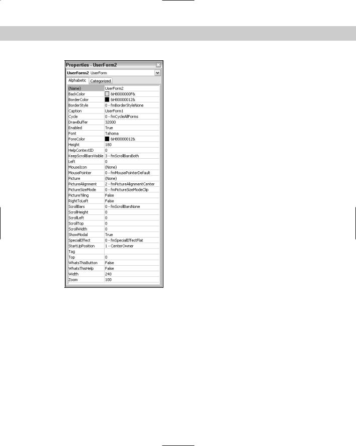
Figure 37-7 shows the property box when you insert a user form. You can easily change the dialog box’s properties in the property box.
One property you’ll want to change is the Caption property of the dialog box. The dialog box should have a caption that summarizes its purpose. When you type the new caption in the property box, the caption on the dialog box changes at the same time.
Chapter 37 Programming with Visual Basic for Applications 1067
Figure 37-7: When you insert a user form (dialog box), the Properties window lists all its properties.
Adding dialog-box controls
One of the more commonly used controls is the command button. A command button is a button you click in the dialog box to execute an action. The most familiar command buttons are the OK and Cancel buttons.
Add a command button
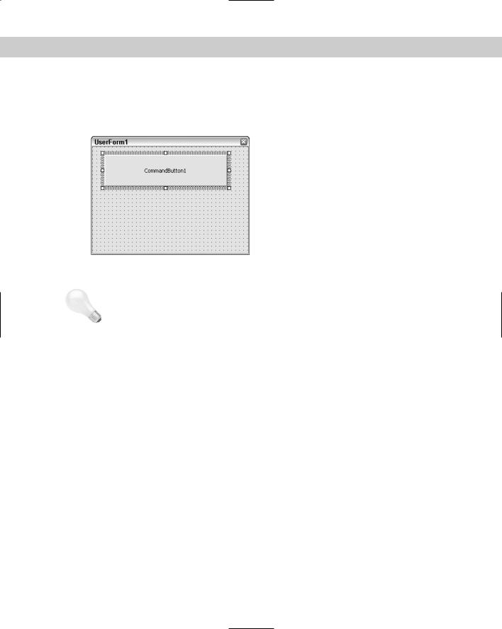
To add a command button, click CommandButton on the Toolbox toolbar. Move your cursor over the dialog box and drag to create a button. Figure 37-8 shows a dialog box with a new command button. The selection border and handles indicate that the button is a selected
1068 Part VII Programming AutoCAD
object. You can move the button by dragging it. You can resize the button by dragging one of the handles. Add all the command buttons you need. Don’t forget to include at least a Cancel button. Many dialog boxes also have an OK button. If you know in advance all the controls you’ll need, you can add them all at once.
Figure 37-8: A dialog box with one selected command button.
Tip There’s an art to laying out a dialog box so that it’s clear and easy to understand. After a while you’ll get the hang of it. Pay more attention to the dialog boxes you use every day to pick up some design pointers.
Just as the dialog box has properties, each control on the dialog box has properties. When a control such as a command button is selected, you see its properties in the Properties window. You generally would change at least the caption and the name of a command button. It’s a good idea to change the names to something meaningful rather than using the default name. For example, instead of CommandButton1, use something such as cmdDrawBox or cmdOk.
Write the VBA Code for a command button
After you create a command button, you can attach VBA code to it. To attach VBA code to a control, double-click the control. The text editor opens with the Sub and End Sub lines already entered for you. Type the code you want to attach to the button.
VBA dialog boxes are modal by default, which means that they must be closed before AutoCAD can do anything further. To close a dialog box after your VBA code has run, use Unload Me at the end of a routine.
To run VBA code attached to a dialog box, you need to show the dialog box so you can use it — click a command button, type in text, and so on. The VBA IDE creates private subroutines for each dialog box control. To show the dialog box, start a new module and create code that looks like the code in this example.
Sub DrawArc()
FormArc.Show
End Sub

Chapter 37 Programming with Visual Basic for Applications 1069
FormArc is the name of the user form in this example. Don’t forget to name the user form in the Properties window. Also, remember to name the module, because the module name is what appears in the Macro dialog box when you want to run the routine.
Add a label
A command button is quite simple. You just click it, and it performs. You can label its function right on the command button. However, most other controls require some more explanation. For example, if you want the user to type in text, you need a text box. However, a text box has no caption. Therefore, you need to add instructions to the user. A dialog box may also need other instructions to clarify the purpose of the controls, which responses are required, and so on.
You add instructions with the Label tool on the Toolbox toolbar. Click Label and drag a rectangle on your dialog box. Then type the label. You can resize or move the label as needed.
Add other dialog-box controls
The code for some of the dialog-box controls can be quite complex. For example, to create a list box that enables the user to choose from an existing list of options, you’d probably create the list of options in advance. For help on creating dialog boxes, choose Help Microsoft Visual Basic Help. On the Contents tab, double-click Microsoft Forms Reference, then Microsoft Forms Object Model Reference. From there, you may want to double-click Objects, Collections, and Controls. You can double-click a control, such as the ListBox control, and read more about it. The specific controls also offer hyperlinks to examples you can look at.
STEP-BY-STEP: Creating a Dialog Box with a Command Button
1.Open a new drawing in AutoCAD using the acad.dwt template. Choose Tools Macro Visual Basic Editor.
2.Choose Insert UserForm. If the Toolbox toolbar covers the user form or project window, drag it to the right.
3.With the user form active (click its title bar to make it active), change the Name property of the user form to frmArc in the Properties window.
4.Change the Caption property of the user form to Draw an arc. Watch the caption of the user form change as you type.
5.Choose CommandButton on the Toolbox toolbar. (It’s the last button in the second row. If you don’t see the Toolbox toolbar, click in the user form on the right side of your screen.) Move the cursor over the user form and drag to create a wide button across the upper center of the user form.
6.Change the Caption property of the button to Draw the Arc! Change the name property to cmdDrawArc.
7.Again, choose CommandButton on the Toolbox toolbar. Create a smaller button below the first one near the right side of the user form.
8.Change the Caption property of the smaller button to Cancel. Change its name property to cmdCancel. Your dialog box should look like the one in Figure 37-9.
1070 Part VII Programming AutoCAD
Figure 37-9: A simple dialog box created in VBA.
9.Double-click the larger button. In the text editor, type the following code at the cursor’s current location between the Private Sub and End Sub statements:
‘declare variables Dim startang As Double Dim endang As Double
Dim ctr(0 To 2) As Double Dim rad As Double
Dim newarc As Object ‘specify arc parameters startang = 0
‘angles are in radians. endang = 100
ctr(0) = 5 ctr(1) = 2 ctr(2) = 0 rad = 2 ‘draw arc
Set newarc = ThisDrawing.ModelSpace.AddArc(ctr, rad, startang, endang) ‘close dialog box
Unload Me
10.From the left (Object) drop-down list at the top of the text editor, choose cmdCancel to add the code for the second button. In the space below the start of the subroutine
(Private Sub cmdCancel_Click()), type Unload Me.
11.Choose Insert Module. In the new text editor, type the following to display the dialog box.
Sub DrawArc() frmArc.Show
Visual Basic places the End Sub statement for you after the code.
12.In the Properties window, change the module’s name to DrawArc.
13.Click Save on the toolbar and save the file in your AutoCAD Bible folder as ab37-03.dvb.

Chapter 37 Programming with Visual Basic for Applications 1071
14.Return to your drawing. Choose Tools Macro Macros. In the Macro dialog box, choose DrawArc and click Run.
15.Click the large button. AutoCAD draws the arc.
Getting user input for a circle radius
Here’s another example of a routine that draws a circle, but here you get user input for the radius using the VAL function. The VAL function returns a numerical value from a text string. Here you create a text box that enables users to type in a radius. The VAL function converts the string in the text box to a number and uses it as the circle’s radius. Follow these steps:
1.Open AutoCAD with a new drawing using the acad.dwt template. Open the VBA IDE.
2.Choose Insert UserForm.
3.In the Properties window, change the name of the form to frmDrawCircle and the caption to Draw a Circle Demo.
4.From the Toolbox toolbar, choose Label and drag a small rectangle on the left side of the form, around the middle.
5.Change the caption to Radius.
6.Choose Textbox on the Toolbox toolbar and drag a box on the form to the right of the label.
7.Change the name to txtRadius.
8.Choose CommandButton on the Toolbox toolbar and drag a larger box at the top-center of the form.
9.Change the name to cmdDrawCircle and the caption to Draw Circle.
10.Double-click this command button to bring up the code editor in the cmdDrawCircle_Click () subroutine.
11.Add the following lines:
Dim dCenter(0 To 2) As Double Dim dRadius As Double
Dim myCircle as AcadCircle
dCenter(0) = 0# dCenter(1) = 0# dCenter(2) = 0#
dRadius = Val(txtRadius)
Set myCircle = ThisDrawing.ModelSpace.AddCircle(dCenter, dRadius) myCircle.Update
12.Close the code window. Save the routine if you want. On the VBA IDE menu, choose Run Run Sub/UserForm. Visual Basic returns you to your drawing and displays the dialog box. Enter a number for the radius and click the Draw Circle command button.
13.Add as many circles as you like. Click the Close box of the dialog box when you’re done.