

- •Foreword
- •Preface
- •Is This Book for You?
- •How This Book Is Organized
- •How to Use This Book
- •Doing the Exercises
- •Conventions Used in This Book
- •What the Icons Mean
- •About the CD-ROM
- •Other Information
- •Contacting the Author
- •Acknowledgments
- •Contents at a Glance
- •Contents
- •Getting Acquainted with AutoCAD and AutoCAD LT
- •Starting AutoCAD and AutoCAD LT
- •Creating a New Drawing
- •Using the AutoCAD and AutoCAD LT Interface
- •Creating Your First Drawing
- •Saving a Drawing
- •Summary
- •Creating a New Drawing from a Template
- •Working with Templates
- •Opening a Drawing with Default Settings
- •Opening an Existing Drawing
- •Using an Existing Drawing as a Prototype
- •Saving a Drawing Under a New Name
- •Summary
- •The Command Line
- •Command Techniques
- •Of Mice and Pucks
- •Getting Help
- •Summary
- •Typing Coordinates
- •Displaying Coordinates
- •Picking Coordinates on the Screen
- •Locating Points
- •Summary
- •Unit Types
- •Drawing Limits
- •Understanding Scales
- •Inserting a Title Block
- •Common Setup Options
- •The MVSETUP Command
- •Summary
- •Using the LINE Command
- •Drawing Rectangles
- •Drawing Polygons
- •Creating Construction Lines
- •Creating Rays
- •Summary
- •Drawing Circles
- •Drawing Arcs
- •Creating Ellipses and Elliptical Arcs
- •Making Donuts
- •Placing Points
- •Summary
- •Panning
- •The ZOOM Command
- •Aerial View
- •Named Views
- •Tiled Viewports
- •Snap Rotation
- •User Coordinate Systems
- •Isometric Drawing
- •Summary
- •Editing a Drawing
- •Selecting Objects
- •Summary
- •Copying and Moving Objects
- •Using Construction Commands
- •Creating a Revision Cloud
- •Hiding Objects with a Wipeout
- •Double-Clicking to Edit Objects
- •Grips
- •Editing with the Properties Palette
- •Selection Filters
- •Groups
- •Summary
- •Working with Layers
- •Changing Object Color, Linetype, and Lineweight
- •Working with Linetype Scales
- •Importing Layers and Linetypes from Other Drawings
- •Matching Properties
- •Summary
- •Drawing-Level Information
- •Object-Level Information
- •Measurement Commands
- •AutoCAD’s Calculator
- •Summary
- •Creating Single-Line Text
- •Understanding Text Styles
- •Creating Multiline Text
- •Creating Tables
- •Inserting Fields
- •Managing Text
- •Finding Text in Your Drawing
- •Checking Your Spelling
- •Summary
- •Working with Dimensions
- •Drawing Linear Dimensions
- •Drawing Aligned Dimensions
- •Creating Baseline and Continued Dimensions
- •Dimensioning Arcs and Circles
- •Dimensioning Angles
- •Creating Ordinate Dimensions
- •Drawing Leaders
- •Using Quick Dimension
- •Editing Dimensions
- •Summary
- •Understanding Dimension Styles
- •Defining a New Dimension Style
- •Changing Dimension Styles
- •Creating Geometric Tolerances
- •Summary
- •Creating and Editing Polylines
- •Drawing and Editing Splines
- •Creating Regions
- •Creating Boundaries
- •Creating Hatches
- •Creating and Editing Multilines
- •Creating Dlines
- •Using the SKETCH Command
- •Digitizing Drawings with the TABLET Command
- •Summary
- •Preparing a Drawing for Plotting or Printing
- •Creating a Layout in Paper Space
- •Working with Plot Styles
- •Plotting a Drawing
- •Summary
- •Combining Objects into Blocks
- •Inserting Blocks and Files into Drawings
- •Managing Blocks
- •Using Windows Features
- •Working with Attributes
- •Summary
- •Understanding External References
- •Editing an Xref within Your Drawing
- •Controlling Xref Display
- •Managing Xrefs
- •Summary
- •Preparing for Database Connectivity
- •Connecting to Your Database
- •Linking Data to Drawing Objects
- •Creating Labels
- •Querying with the Query Editor
- •Working with Query Files
- •Summary
- •Working with 3D Coordinates
- •Using Elevation and Thickness
- •Working with the User Coordinate System
- •Summary
- •Working with the Standard Viewpoints
- •Using DDVPOINT
- •Working with the Tripod and Compass
- •Getting a Quick Plan View
- •Shading Your Drawing
- •Using 3D Orbit
- •Using Tiled Viewports
- •Defining a Perspective View
- •Laying Out 3D Drawings
- •Summary
- •Drawing Surfaces with 3DFACE
- •Drawing Surfaces with PFACE
- •Creating Polygon Meshes with 3DMESH
- •Drawing Standard 3D Shapes
- •Drawing a Revolved Surface
- •Drawing an Extruded Surface
- •Drawing Ruled Surfaces
- •Drawing Edge Surfaces
- •Summary
- •Drawing Standard Shapes
- •Creating Extruded Solids
- •Drawing Revolved Solids
- •Creating Complex Solids
- •Sectioning and Slicing Solids
- •Using Editing Commands in 3D
- •Editing Solids
- •Listing Solid Properties
- •Summary
- •Understanding Rendering
- •Creating Lights
- •Creating Scenes
- •Working with Materials
- •Using Backgrounds
- •Doing the Final Render
- •Summary
- •Accessing Drawing Components with the DesignCenter
- •Accessing Drawing Content with Tool Palettes
- •Setting Standards for Drawings
- •Organizing Your Drawings
- •Working with Sheet Sets
- •Maintaining Security
- •Keeping Track of Referenced Files
- •Handling Errors and Crashes
- •Managing Drawings from Prior Releases
- •Summary
- •Importing and Exporting Other File Formats
- •Working with Raster Images
- •Pasting, Linking, and Embedding Objects
- •Summary
- •Sending Drawings
- •Opening Drawings from the Web
- •Creating Object Hyperlinks
- •Publishing Drawings
- •Summary
- •Working with Customizable Files
- •Creating Keyboard Shortcuts for Commands
- •Customizing Toolbars
- •Customizing Tool Palettes
- •Summary
- •Creating Macros with Script Files
- •Creating Slide Shows
- •Creating Slide Libraries
- •Summary
- •Creating Linetypes
- •Creating Hatch Patterns
- •Summary
- •Creating Shapes
- •Creating Fonts
- •Summary
- •Working with Menu Files
- •Customizing a Menu
- •Summary
- •Introducing Visual LISP
- •Getting Help in Visual LISP
- •Working with AutoLISP Expressions
- •Using AutoLISP on the Command Line
- •Creating AutoLISP Files
- •Summary
- •Creating Variables
- •Working with AutoCAD Commands
- •Working with Lists
- •Setting Conditions
- •Managing Drawing Objects
- •Getting Input from the User
- •Putting on the Finishing Touches
- •Summary
- •Understanding Local and Global Variables
- •Working with Visual LISP ActiveX Functions
- •Debugging Code
- •Summary
- •Starting to Work with VBA
- •Writing VBA Code
- •Getting User Input
- •Creating Dialog Boxes
- •Modifying Objects
- •Debugging and Trapping Errors
- •Moving to Advanced Programming
- •A Final Word
- •Installing AutoCAD and AutoCAD LT
- •Configuring AutoCAD
- •Starting AutoCAD Your Way
- •Configuring a Plotter
- •System Requirements
- •Using the CD with Microsoft Windows
- •What’s on the CD
- •Troubleshooting
- •Index

986 Part VII Programming AutoCAD
Introducing Visual LISP
Visual LISP (VLISP) is an integrated development environment (IDE) that provides an easy-to- use interface to help you create code, debug errors, and test programs.
Some useful Visual LISP features include the following:
Syntax checker and highlighting to help correct syntax errors
File compilation for security and faster execution
Debugger, with support for stepping through source code to find errors
Helpful Inspect and Watch windows for querying a value or examining a variable during execution
Context-sensitive help
Management of multiple file applications from a project window
Compiled multiple projects, as well as other files, using the application wizard
Console history, which makes it possible to recall previously entered information
Opening Visual LISP
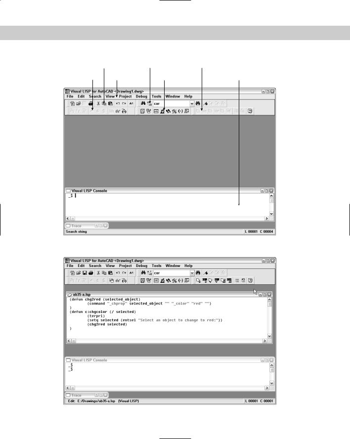
To start Visual LISP, you can either type Vlide at the AutoCAD command prompt, or choose Tools AutoLISP Visual LISP Editor. At any time, you can switch to Visual LISP using either of these methods. Figure 34-1 shows your screen after you open Visual LISP.
AutoLISP and Visual LISP are discussed throughout Chapters 34, 35, and 36. Although this book does not provide complete coverage of either AutoLISP or Visual LISP, many of the major features are explained within these three chapters.
Opening and loading an AutoLISP file with Visual LISP
As soon as you’re in the Visual LISP environment, you can create a new AutoLISP file or open an existing file.
To edit or view a file in the Visual LISP text editor, follow these steps:
1.Choose File Open File from the Visual LISP menu.
2.In the Open File to Edit/View dialog box, locate and choose the file you want to open.
3.Click Open. Visual LISP opens the file in its own window, as shown in Figure 34-2.
When you open a file, the title bar of its window displays a blank paper icon to show that the file has not been changed. If you make any changes to the file, Visual LISP adds a pencil to the image to show that you’ve edited the file.
You can open as many files as you want.
Chapter 34 Understanding AutoLISP and Visual LISP Basics |
987 |
Standard toolbar |
Search toolbar |
Tools toolbar |
|
Debug toolbar |
Menu |
View toolbar |
Console window |
Figure 34-1: The Visual LISP window.
Figure 34-2: An AutoLISP file open in its own window in the Visual LISP window.
988 Part VII Programming AutoCAD
Loading an AutoLISP file
To use the AutoLISP program in AutoCAD, you must load it. You can load it from within Visual LISP or from within AutoCAD.
If you have a file open in Visual LISP, choose Tools Load Text in Editor or choose Load Active Edit Window from the Tools toolbar.
If you’re in AutoCAD, you can load AutoLISP files into AutoCAD in two ways. One method is on the command line. To load 3DARRAY from the command line, type (load “3darray”) . The parentheses are required, and they indicate that you’re entering an AutoLISP expression. AutoLISP requires the quotation marks because you’re specifying a filename. AutoCAD responds with 3DARRAY loaded.
When you enter the command to load 3DARRAY, AutoCAD searches all support paths for a file called 3darray.lsp. At installation time, AutoCAD automatically configures the support-file search path to include the path of AutoCAD 2005\Support. For a full list of folders in
the support-file search path, choose Tools Options and click the Files tab. Double-click the Support File Search Path item.
Note AutoLISP files have the extension of .lsp. However, for security and speed, you can compile AutoLISP routines as .fas or .vlx project application files. AutoCAD loads .vlx first, then .fas, and .lsp files last. For example, if you have both a redline.vlx and a redline.lsp, AutoCAD loads the redline.vlx file. If, however, the .lsp file is newer than the .fas file, AutoCAD will load the .lsp file. If an AutoLISP routine is associated with a menu, it has an .mnl extension. For more information, see Chapter 33.
If your file is not in a folder in AutoCAD’s support file search path, you must specify the full path name. To specify the full path to the routine type, you would enter:
(load “c:/Program Files/AutoCAD 2005/Support/3darray”) /
or
(load “c:\\Program Files\\AutoCAD 2005\\Support\\3darray”)
The backslash (\) has special meaning in AutoLISP, so you need to use two of them or a regular slash (/) when specifying a path. (The backslash character tells AutoLISP to interpret the following character as a special control code. To use a double quote in an AutoLISP expression, for example, precede it with a backslash.)
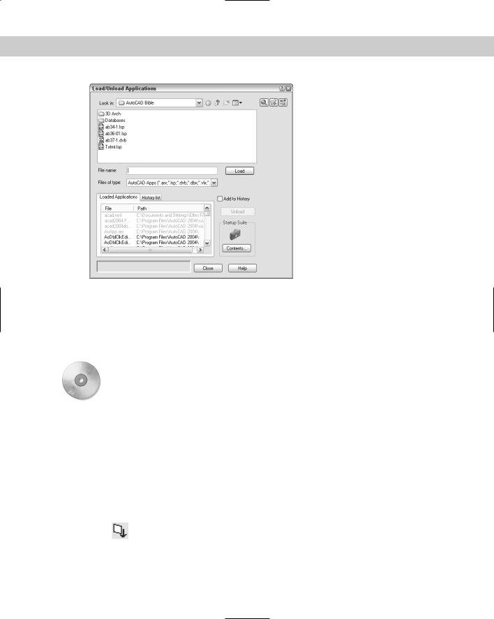
You can also load AutoLISP routines with the APPLOAD command by choosing Tools Load Application or by typing appload at the command line. AutoCAD opens the Load/ Unload Applications dialog box, shown in Figure 34-3.
Use this dialog box to load FAS, VLX, and LSP files. (You can also load other types of programming files in this dialog box — ARX, DVB, and DBX files.) If you check Add to History, AutoCAD lists previously loaded applications in the dialog box — just click the History List tab. Locate and choose the file you want to load and click Load.
Chapter 34 Understanding AutoLISP and Visual LISP Basics |
989 |
Figure 34-3: The Load/Unload Applications dialog box.
Using an AutoLISP routine in AutoCAD
After you load an AutoLISP routine, you can use it. How you use the routine depends on the routine. If the program creates a function, you can type the function’s name on the command line like any other AutoCAD command. Most routines contain prompts to guide you in their use.
On the |
The AutoLISP file used in the following Step-by-Step exercise on loading and using an |
CD-ROM |
AutoLISP routine, circle3.lsp, is in the Drawings folder on the CD-ROM. |
STEP-BY-STEP: Loading and Using an AutoLISP Routine
1.Use Windows Explorer to copy circle3.lsp from the CD-ROM to your AutoCAD 2005\Support\ folder or to a folder you added to the support file search path.
2.Create a new drawing using any template.
3.Choose Tools AutoLISP Visual LISP Editor. The Visual LISP IDE opens.
4.If any AutoLISP files are displayed in the main area, click their Close boxes.
5.Choose Open on the Standard Visual LISP toolbar. In the Open dialog box, navigate to the folder where you saved circle3.lsp and double-click it. It appears in the Visual LISP window.
6.Choose Load Active Edit Window from the Visual LISP Tools toolbar. The Visual LISP Console window confirms that circle3.lsp has been loaded.
990 Part VII Programming AutoCAD
7.Choose Activate AutoCAD from the Visual LISP View toolbar. Visual LISP returns you to AutoCAD.
8.Now that circle3 has been loaded, at the command prompt, type circle3 .
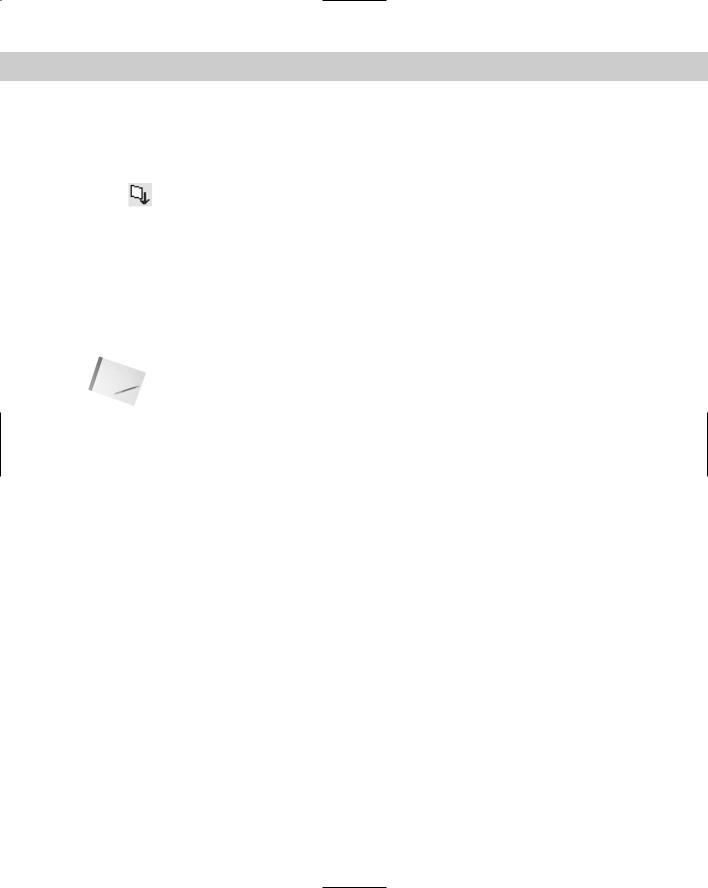
9.At the Please click a point: prompt, pick any point on-screen. You see a 3-unit radius circle with its center at the point you picked, as shown in Figure 34-4.
Figure 34-4: The circle drawn using the circle3
AutoLISP routine.
10. Save your drawing in your AutoCAD Bible folder as ab34-01.dwg.
Looking at an AutoLISP routine
To examine the contents of the circle3.lsp file, open it in the Visual LISP editor. Figure 34-5 shows the circle3 routine. At this point, ignore the color formatting, which is discussed later in this chapter.
Figure 34-5: The circle3 AutoLISP routine.
This figure illustrates several general characteristics of AutoLISP routines:
As in many programming languages, indentation is used in AutoLISP to make it easier to read the code. It has no effect on the operation of the routine.
The returns at the end of each line also make it easier to read and understand the code. All five lines could be placed on a single line, and the program would work exactly the same way.
All AutoLISP statements are placed in parentheses. Therefore, whenever you open a parenthesis you must close it. Every AutoLISP routine must have the same number of left and right parentheses. The physical location of a right parenthesis is not relevant — it can be placed on a new line or positioned several spaces away from the left parenthesis. In both cases, the pair is interpreted the same way.
AutoLISP is interpreted from the innermost parenthetical elements first. On line 3 of the code shown in Figure 34-5, for instance, (getpoint) is done first, and then the result is
used for the (setq pt (getpoint)) expression. This is analogous to mathematics, as in the expression (3 + (5 × 4)), where 5 × 4 is computed first and the result is added to 3.

Chapter 34 Understanding AutoLISP and Visual LISP Basics |
991 |
At the end of the first line is a comment, ;Creates a circle of radius 3. The program ignores any text preceded by a semicolon. Use this technique to place explanations in your routines to help you and others understand what the routine is doing.
The following explains the routine in Figure 34-5 line by line:
Line 1 begins with an open parenthesis that is balanced with the one on line 5. This pair of parentheses delineates the body of the function. The line begins with defun, which stands for define function, and the function is called c:circle3. When you prefix the function with c:, you can use it in AutoCAD by just entering circle3 at the command line like any other AutoCAD command. (The c: stands for command and has no relation to your hard drive, which is also usually called c:.) You could use just circle3, but you would have to type (circle3) at the command line to use the routine. The last item on Line 1 is (/ pt). The pt after the slash means that pt is a local variable. A variable stores a value for later use in the routine. A local variable is used only in its own routine and is not retained for use in other routines. If you replaced (/ pt) with simply ( ), the pt variable would be available to other AutoLISP routines as well.
Line 2 is the simplest line in this routine — it simply prints the statement Please click a point: at the command line. Anything in the quotes after princ will be printed on the AutoCAD command line. In this case, the statement is used as a prompt to tell the user to pick a point.
Line 3 is typical of AutoLISP routines in which nested parentheses can drive the reader crazy. Remember to read from the innermost parenthetical element outward. So reading from the innermost parenthetical element, you have first (getpoint). This means to simply get a point. Any of the AutoCAD input methods work — clicking the screen, typing coordinates for a point, or using object snaps. Reading outward you have (set q pt (getpoint)). The statement setq means that the variable pt is set to whatever comes back from getpoint. So if you enter the coordinates 2,2 by typing them or selecting them on the screen, the variable pt equals 2,2.
Line 4 reads (command “_circle” pt “3”). The command function in AutoLISP is one of the easier functions to understand. It simply executes whatever AutoCAD command is specified in the quotes that follow, using all subsequent arguments. When the CIRCLE command is invoked in AutoCAD, it asks for the center point first and then the radius. Line 4 starts the CIRCLE command, uses for the center point whatever is assigned to the variable pt, and sets the radius to 3 units.
Note An underscore precedes the CIRCLE command so that it can be translated into other language versions of AutoCAD.
Using the Visual LISP interface
The Visual LISP window contains a number of tools that make your programming life simpler. These tools represent the difference between the old way of writing AutoLISP code — creating text files in a text editor — and the new visual way, with tools that help you format and complete your code. Some of the more useful tools include:
Format Edit Window: Choose Format Edit Window on the Tools toolbar (or
choose Tools Format Code in Editor) to indent code (and comments) so that it’s more readable. Indenting code helps you understand levels of nested parentheses more clearly. Of course, you can indent your code manually, but automatic indenting is a boon to all AutoLISP programmers.
992 Part VII Programming AutoCAD
Format Selection: Select the code you want to format. Then choose Format Selection on the Tools toolbar (or choose Tools Format Code in Selection)
to indent only the selected code.
Check Edit Window: Choose Check Edit Window from the Tools toolbar (or choose Tools Check Text in Editor) to perform a preliminary evaluation prior
to loading the file. This evaluation checks the code for unbalanced parentheses, invalid function definition formatting (an attempt to redefine a built-in or protected function), and many other common errors. Visual LISP opens the Build Output window to show you the results.
Check Selection: Select the code you want to check. Choose Check Selection from
the Tools toolbar (or choose Tools Check Selection) to perform a preliminary evaluation on selected code. Visual LISP opens the Build Output window to show you the results.
Parentheses Matching: The most common error for an AutoLISP programmer is incorrect parentheses matching. Visual LISP enables you to jump between matching parentheses and quickly check your current nesting level as you develop your application. While you can use the menu items (choose Edit Parentheses Matching Match Forward and Match Backward), you’ll find that the keyboard shortcuts distract you less from the code you’re looking at. To find a matching right parenthesis, press Ctrl+]. To find a left matching parenthesis, press Ctrl+[.
Tip |
You can highlight all the code between matching parentheses. To highlight from left to right, |
|
place the cursor in front of a left parenthesis and press Ctrl+Shift+] or simply double-click. To |
|
highlight from right to left (backwards), place the cursor after a right parenthesis and press |
|
Ctrl+Shift+[ or double-click. |
Load Selection: You’ve already seen how to load the code in the active window. You can also load selected code. Select the code you want to load and choose
Load Selection from the Tools toolbar or choose Tools Load Selection.
Comment Block: In Figure 34-5, you see an example of a comment. Visual LISP supports several comment styles, which Chapter 35 covers. Visual LISP simplifies
the addition of a 3-semicolon comment. To place a 3-semicolon comment, highlight the text you want to change into a comment and click Comment Block on the Tools toolbar. See Chapter 35 for more information on creating comments.
Uncomment Block: To remove a 3-semicolon comment, click Uncomment Block on the Tools toolbar.
Another feature of Visual LISP is the Console window. The Console window usually resides at the bottom of the Visual LISP window. The Console window is similar to the AutoCAD command line. Just as you can enter AutoLISP expressions on the AutoCAD command line, as explained later in this chapter, you can also enter AutoLISP expressions in the Console window and see the results. Each line uses a _$ prompt.
A nice feature of the Console window is that Visual LISP remembers everything you enter. You can retrieve it by pressing Tab for a forward history or Shift+Tab for a backward history.