

Basic Analog and Digital (Students guide, v13)
.pdfChapter 3: Basic Analog to Digital Conversion · Page 51
The Calc_Volts subroutine is empty right now, but we will develop the code for this subroutine shortly. The subroutine will calculate the measured voltage to the hundredth’s decimal place.
Calc_Volts:
RETURN
At present, the Display subroutine just displays the binary output for each analog voltage sample taken by the ADC0831. It will be modified to display the decimal equivalent of the 8-bit binary value. It will also be modified to display the voltage measurement.
The following DEBUG commands send the cursor to the top-left "home" position in the Debug Terminal. Then it prints the message in quotes. The modifier BIN8 makes it so the value of the adcBits variable is displayed as 8 binary digits.
DEBUG HOME
DEBUG "8-bit binary value: ", BIN8 adcBits
If the number of digits displayed is likely to vary, when using the DEBUG HOME command, always specify how many digits the numeric outputs should have with modifiers like BIN8, DEC3, etc. When DEBUG CLS is used, it’s OK to skip specifying the number of digits, so modifiers such as BIN and DEC can be used instead.
The DEBUG HOME command is better for programs that cycle through loops where the Debug Terminal display is updated frequently and rapidly. When DEBUG CLS is used under these circumstances, the repeated clearing the Debug Terminal causes a flicker that makes the display difficult to read.
The RETURN command sends the program back to the line immediately following the
GOSUB Display command.
We will modify the Display subroutine to display the decimal equivalent of the binary contents of adcBits in the Debug Terminal. Code will also be added to make the Debug Terminal display our DVM reading.

Page 52 · Basic Analog and Digital
Interpreting the Output
The ADC0831 measures an analog voltage at its input. Then it sends the BASIC Stamp a binary number describing the value it measured. For now, we’ll focus on a voltage scale that starts with 0 volts and ends at 5 volts.
With an 8-bit binary number, you can start counting with 00000000 and count all the way up to 11111111. Translated to decimal numbers, it's the same as counting from 0 to 255. When applied to a 5 volt scale that starts at 0 volts, it’s the same as counting from 0 to 5 volts using 255 voltage steps.
For the 5 volt scale, when the ADC0831 measures 0 volts, you get 00000000. When it measures 5 volts, the output is 11111111. It turns out that the Debug Terminal output 10110100 from Figure 3-4 is the same as the decimal number 180. Decimal-180 in turn corresponds to a measured voltage of 3.53 volts.
Binary to Decimal Conversion Revisited
So how do we know that 256 combinations can come from an 8-bit binary number? Remember, you can always tell how many numbers (combinations of 0s and 1s) can come from a given number of bits by using this formula from Chapter #2:
combinations =2bits
This means the number of combinations equals two raised to the power of the number of bits. For 8-bits, the number of combinations is 28 = 256. For 12-bits, the number of combinations is 212 = 4096, and so on.
Let's use the two-step method from Chapter #2 to convert the 8-bit binary number 10100101 to its decimal equivalent. Here is a repeat of the bit multipliers table to work with:
Table 3-1:Bit Multipliers for an 8-bit Binary Number
Bit |
7 |
6 |
5 |
4 |
3 |
2 |
1 |
0 |
|
|
|
|
|
|
|
|
|
Multiplier |
128 |
64 |
32 |
16 |
8 |
4 |
2 |
1 |
|
|
|
|
|
|
|
|
|

Chapter 3: Basic Analog to Digital Conversion · Page 53
First, multiply each bit by its power of two from Table 3-1:
128 x 1 = 128
64 x 0 = 0
32 x 1 = 32
16 x 0 = 0
8 x 0 = 0
4 x 1 = 4
2 x 0 = 0
1 x 1 = 1
Second, add all 8 of the decimal values:
128 + 0 + 32 + 0 + 0 + 4 + 0 + 1 = 165
Now we know the binary number 10100101 is equal to the decimal number 165. To display this conversion, a single DEBUG command can be added to the Display subroutine. Added lines are shown with a "Ƒ".
Display: |
|
DEBUG HOME, "8 bit binary value: ", BIN8 adcBits |
'Ƒ new line |
DEBUG CR, CR, "Decimal value: ", DEC3 adcBits |
|
RETURN |
|
The command DEBUG CR, CR, "Decimal value: ", DEC3 adcBits tells the Debug Terminal to display two carriage returns followed by the message in quotes, followed again by the 3-digit decimal value of adcBits. If the actual number only has one or two digits, the Debug Terminal will automatically display leading zeros since DEC3 was specified. For example, the number 7 will display as 007, and the number 85 as 085, etc.
With some careful adjustment of the pot, we can check our work using output sample shown in Figure 3-6.

Page 54 · Basic Analog and Digital
Figure 3-6
Debug Terminal
Output for Program
Listing 3.1,
Revision 1.
Calculate Voltage
Now that we know the decimal equivalent of the ADC0831’s binary output, we can do a few calculations to get the measured voltage. To find out what voltage the decimal number corresponds to, we need to calculate where in the voltage range the number falls. Here is an effective way to think about the problem.
•We know that the voltage is on a 0 to 5 volt scale, and we know that the ADC0831’s output is on a scale from 0 to 255.
•In other words, the measured voltage is to 5 as the A/D output is to 255.
This translates to fractions as:
Voltage |
= |
Decimal A / D Output |
|
5 |
255 |
||
|
We can re-arrange this equality to calculate the voltage:
Voltage= 5 × (Decimal A/D Output)
255

Chapter 3: Basic Analog to Digital Conversion · Page 55
So, now we know to multiply by 5 and divide by 255 for a 5 volt scale with 256 levels. We can calculate the voltage from Figure 3-6 where the ADC0831’s output is 10100101 = 165. The measured voltage is:
Voltage = 5 ×255165 = 3.24 Volts rounded to two decimal places.
To calculate and display this voltage using the BASIC Stamp, we’ll add some code to both the Calc_Volts and Display subroutines. First, the voltage equation needs to be expressed in PBASIC code. Here is an example of some code that could reasonably be expected to work.
v = 5 * adcBits / 255
This PBASIC calculation looks like it will give us the output we want, but it won’t. It’s instructive to try it this way and see what happens. Modify the Calc_Volts and Display subroutines in Program Listing 3.1 as follows:
Calc_Volts:
v = 5 * adcBits / 255 'Ƒ new line RETURN
Display: DEBUG HOME
DEBUG "8-bit binary value: ", BIN8 adcBits DEBUG CR, CR, "Decimal value: ", DEC3 adcBits
DEBUG CR, CR, "DVM Reading: ", DEC3 v, " Volts" 'Ƒ new line RETURN
We calculated that 165 would lead to a measured voltage of 3.24 volts. The 003 volts shown in Figure 3-7 is only accurate to the nearest volt! What happened?

Page 56 · Basic Analog and Digital
Figure 3-7
Debug Terminal Output for Program Listing 3.1, Revision 2.
The PBASIC command set for the BASIC Stamp does arithmetic using integer values. Integers are the counting numbers: …-2, -1, 0, 1, 2, 3, etc. The largest integer the BASIC Stamp can process is 65535. When using integer arithmetic, the fractional part of any answer is discarded. Fortunately, we can still use integer arithmetic to find the fractional values we are trying to display.
Before dividing, the A/D output is multiplied by 5. This doesn’t cause any problems.
5 × (Decimal A/D Output) is essentially the same as 5 × adcBits .
In our voltage calculation example, that’s 5 × 165 = 825. Since 825 is an integer that is
less than 65535, this part of the calculation goes without a hitch. The problem occurs when we try to divide 825 by 255. The answer has a fractional component that never gets calculated with integer math.
Doing “long division” with a pencil and a piece of paper takes several steps, and it relies solely on integer arithmetic. Let's look at how to calculate the answer for this division problem.

Chapter 3: Basic Analog to Digital Conversion · Page 57
Voltage = 5 × (Decimal A/D Output) = 3 + a remainder of 60 255
In long division, calculating the part of the answer to the right of the decimal point is repetitive. We multiply the remainder by 10, then divide by 255 again, then take another remainder, multiply it by 10, and divide by 255 again, etc. A shortcut to this procedure is to take the remainder, and multiply it by 100, then divide by 255. This gives us two decimal places. Let's try it.
(60×100) ÷ 255 = 6000 ÷ 255 = 23.5924... → 23
Integer Math
Remember: the BASIC Stamp cuts off everything to the right of the decimal point without rounding. This is called truncating. The result we get is 23. This result should have been rounded up to 24 because 23.5294 is more than half way to the next integer value, 24. For now, let's stick with 23 to the right of the decimal point.
Our answer using this algorithm is the integer 3 to the left of the decimal point, and the integer value 23 to the right of the decimal point. Since we used only integers in our arithmetic, it should work using PBASIC and the BASIC Stamp.
What’s an Algorithm? An algorithm is a procedure for solving a problem. The procedure is broken down into repeatable steps.
Since the BASIC Stamp works with integers, it's not surprising that there is a PBASIC command to calculate the integer remainder of a division problem. The operator for division is / and the operator for getting the remainder is //. Let's try converting this algorithm into PBASIC code to do the work for us. The steps for long division below show the PBASIC commands corresponding to the steps in the algorithm.
|
|
|
5×adcBits |
v+r |
|
|
|
|
|
|
|||
v=5*adcBits/255 |
255 |
R=(5*adcBits//255) |
||||
|
|
|
v2 |
|
|
|
|
|
|
|
|
|
|
|
|
|
100×r |
|
|
|
v2=(100*R)/255 |
255 |
|
|
|
||
Page 58 · Basic Analog and Digital
This gives us our three PBASIC commands for calculating the values to the left and right of the decimal point. To reconstruct the fractional value on the display, we’ll print a period "." in-between the two values.
The first of the three commands is already in our Calc_Volts subroutine. Just add the other two instructions to complete the algorithm.
Calc_Volts: |
|
|
||
v |
= 5 |
* adcBits / 255 |
'Ƒ |
|
r |
= 5 |
* adcBits // 255 |
new line |
|
v2 = 100 * R / 255 |
'Ƒ |
new line |
||
RETURN |
|
|
|
|
The Display subroutine also needs to be updated to print the two variable values with a period in between them. Make sure to update the line in the Display subroutine exactly as shown below.
Display:
DEBUG HOME
DEBUG "8-bit binary value: ", BIN8 adcBits
DEBUG CR, CR, "Decimal value: ", DEC3 adcBits
DEBUG CR, CR, "DVM Reading: " |
'Ƒ |
new line |
DEBUG DEC1 v, ".", DEC2 v2, " Volts" |
'Ƒ |
new line |
RETURN |
|
|
Now run the program again, and see what happens. Figure 3-8 shows an output sample, which is now almost ready to display to the nearest hundredth of a volt. All that needs to be corrected is a rounding error in the hundredths decimal place.
Chapter 3: Basic Analog to Digital Conversion · Page 59
Figure 3-8
Debug
Terminal
Output for
Program
Listing 3.1,
Revision 3.
All that remains to be done is to correct the rounding error in the hundredth’s place. This rounding problem can be corrected by adding the segment of code shown below to the Calc_Volts subroutine.
Calc_Volts: |
|
|
||||
v = 5 * adcBits / 255 |
|
|||||
r = 5 * adcBits // 255 |
|
|||||
v2 |
= |
100 |
* r / 255 |
'Ƒ new line |
||
v3 |
= |
100 |
* r // 255 |
|||
v3 |
= |
10 * |
v3 / 255 |
'Ƒ new line |
||
IF (v3 |
>= |
5) THEN v2 = v2 + 1 |
'Ƒ new line |
|||
IF (v2 |
>= |
100) THEN |
'Ƒ new line |
|||
|
v = v + |
1 |
'Ƒ new line |
|||
|
v2 |
= |
0 |
|
|
'Ƒ new line |
ENDIF |
|
|
|
|
'Ƒ new line |
|
RETURN |
|
|
|
|
|
|

Page 60 · Basic Analog and Digital
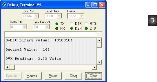
The Output
The output sample from Figure 3-9 indicates that the DVM is now calculating to the hundredth’s decimal place correctly.
Figure 3-9
Debug Terminal Output for Program Listing 3.1, Revision 4.
As soon as you're sure your program works right, save it as P3_1R4.bs2. We will add to both the code and circuit in the next experiment.
About the Code
To round off to the nearest hundredth, we need to know the digit in the thousandth’s place. Using the rules of long division, we can simply set a new variable, v3 equal to the remainder from the calculation for v2, and divide by 255 again.
v3= 100 * R // 255 v3 = 10 * v3 / 255
Instead of using another variable, v3 is simply redefined in the second line. The value of v3 to the right of the equals sign is the one calculated in the first line. The value of v3 to the left of the equals sign is the redefined value, which is ten times the old v3, divided by 255.