

3Data Types
In order to write VHDL code e‰ciently, it is essential to know what data types are allowed, and how to specify and use them. In this chapter, all fundamental data types are described, with special emphasis on those that are synthesizable. Discussions on data compatibility and data conversion are also included.
3.1Pre-Defined Data Types
VHDL contains a series of pre-defined data types, specified through the IEEE 1076 and IEEE 1164 standards. More specifically, such data type definitions can be found in the following packages / libraries:
Package standard of library std: Defines BIT, BOOLEAN, INTEGER, and REAL data types.
Package std_logic_1164 of library ieee: Defines STD_LOGIC and STD_ULOGIC data types.
Package std_logic_arith of library ieee: Defines SIGNED and UNSIGNED data types, plus several data conversion functions, like conv_integer(p), conv_unsigned(p, b), conv_signed(p, b), and conv_std_logic_vector(p, b).
Packages std_logic_signed and std_logic_unsigned of library ieee: Contain functions that allow operations with STD_LOGIC_VECTOR data to be performed as if the data were of type SIGNED or UNSIGNED, respectively.
All pre-defined data types (specified in the packages/libraries listed above) are described below.
BIT (and BIT_VECTOR): 2-level logic (‘0’, ‘1’).
Examples:
SIGNAL x: BIT;
-- x is declared as a one-digit signal of type BIT.
SIGNAL y: BIT_VECTOR (3 DOWNTO 0);
-- y is a 4-bit vector, with the leftmost bit being the MSB.
SIGNAL w: BIT_VECTOR (0 TO 7);
-- w is an 8-bit vector, with the rightmost bit being the MSB.
Based on the signals above, the following assignments would be legal (to assign a value to a signal, the ‘‘<¼’’ operator must be used):
TLFeBOOK
26 |
Chapter 3 |
x <= '1';
--x is a single-bit signal (as specified above), whose value is
--'1'. Notice that single quotes (' ') are used for a single bit.
y <= "0111";
--y is a 4-bit signal (as specified above), whose value is "0111"
--(MSB='0'). Notice that double quotes (" ") are used for
--vectors.
w <= "01110001";
-- w is an 8-bit signal, whose value is "01110001" (MSB='1').
STD_LOGIC (and STD_LOGIC_VECTOR): 8-valued logic system introduced in the IEEE 1164 standard.
‘X’ |
Forcing Unknown |
(synthesizable unknown) |
‘0’ |
Forcing Low |
(synthesizable logic ‘1’) |
‘1’ |
Forcing High |
(synthesizable logic ‘0’) |
‘Z’ |
High impedance |
(synthesizable tri-state bu¤er) |
‘W’ |
Weak unknown |
|
‘L’ |
Weak low |
|
‘H’ |
Weak high |
|
‘–’ |
Don’t care |
|
Examples:
SIGNAL x: STD_LOGIC;
-- x is declared as a one-digit (scalar) signal of type STD_LOGIC.
SIGNAL y: STD_LOGIC_VECTOR (3 DOWNTO 0) := "0001";
--y is declared as a 4-bit vector, with the leftmost bit being
--the MSB. The initial value (optional) of y is "0001". Notice
--that the ":=" operator is used to establish the initial value.
Most of the std_logic levels are intended for simulation only. However, ‘0’, ‘1’, and ‘Z’ are synthesizable with no restrictions. With respect to the ‘‘weak’’ values, they are resolved in favor of the ‘‘forcing’’ values in multiply-driven nodes (see table 3.1). Indeed, if any two std_logic signals are connected to the same node, then conflicting logic levels are automatically resolved according to table 3.1.
STD_ULOGIC (STD_ULOGIC_VECTOR): 9-level logic system introduced in the IEEE 1164 standard (‘U’, ‘X’, ‘0’, ‘1’, ‘Z’, ‘W’, ‘L’, ‘H’, ‘–’). Indeed, the
TLFeBOOK
Data Types |
27 |
Table 3.1
Resolved logic system (STD_LOGIC).
|
X |
0 |
1 |
Z |
W |
L |
H |
- |
|
|
|
|
|
|
|
|
|
X |
X |
X |
X |
X |
X |
X |
X |
X |
0 |
X |
0 |
X |
0 |
0 |
0 |
0 |
X |
1 |
X |
X |
1 |
1 |
1 |
1 |
1 |
X |
Z |
X |
0 |
1 |
Z |
W |
L |
H |
X |
W |
X |
0 |
1 |
W |
W |
W |
W |
X |
L |
X |
0 |
1 |
L |
W |
L |
W |
X |
H |
X |
0 |
1 |
H |
W |
W |
H |
X |
- |
X |
X |
X |
X |
X |
X |
X |
X |
|
|
|
|
|
|
|
|
|
STD_LOGIC system described above is a subtype of STD_ULOGIC. The latter includes an extra logic value, ‘U’, which stands for unresolved. Thus, contrary to STD_LOGIC, conflicting logic levels are not automatically resolved here, so output wires should never be connected together directly. However, if two output wires are never supposed to be connected together, this logic system can be used to detect design errors.
BOOLEAN: True, False.
INTEGER: 32-bit integers (from 2,147,483,647 to þ2,147,483,647).
NATURAL: Non-negative integers (from 0 to þ2,147,483,647).
REAL: Real numbers ranging from 1.0E38 to þ1.0E38. Not synthesizable.
Physical literals: Used to inform physical quantities, like time, voltage, etc. Useful in simulations. Not synthesizable.
Character literals: Single ASCII character or a string of such characters. Not synthesizable.
SIGNED and UNSIGNED: data types defined in the std_logic_arith package of the ieee library. They have the appearance of STD_LOGIC_VECTOR, but accept arithmetic operations, which are typical of INTEGER data types (SIGNED and UNSIGNED will be discussed in detail in section 3.6).
Examples:
x0 |
<= '0'; |
-- bit, std_logic, or |
std_ulogic |
value '0' |
|||
x1 |
<= "00011111"; |
-- bit_vector, std_logic_vector, |
|
||||
|
|
|
-- std_ulogic_vector, |
signed, or |
unsigned |
||
x2 |
<= |
"0001_1111"; |
-- |
underscore allowed to |
ease visualization |
||
x3 |
<= |
"101111" |
-- |
binary representation |
of decimal 47 |
||
TLFeBOOK
28 |
Chapter 3 |
x4 |
<= B"101111" |
-- binary representation of decimal 47 |
x5 |
<= O"57" |
-- octal representation of decimal 47 |
x6 |
<= X"2F" |
-- hexadecimal representation of decimal 47 |
n <= 1200; |
-- integer |
|
m <= 1_200; |
-- integer, underscore allowed |
|
IF ready THEN... |
-- Boolean, executed if ready=TRUE |
|
y <= 1.2E-5; |
-- real, not synthesizable |
|
q <= d after 10 ns; |
-- physical, not synthesizable |
|
Example: Legal and illegal operations between data of di¤erent types. |
||
SIGNAL a: BIT; |
|
|
SIGNAL b: BIT_VECTOR(7 |
DOWNTO 0); |
|
SIGNAL c: STD_LOGIC;
SIGNAL d: STD_LOGIC_VECTOR(7 DOWNTO 0);
SIGNAL e: INTEGER RANGE 0 TO 255;
... |
|
|
a <= b(5); |
-- legal (same scalar type: BIT) |
|
b(0) |
<= a; |
-- legal (same scalar type: BIT) |
c <= |
d(5); |
-- legal (same scalar type: STD_LOGIC) |
d(0) |
<= c; |
-- legal (same scalar type: STD_LOGIC) |
a <= |
c; |
-- illegal (type mismatch: BIT x STD_LOGIC) |
b <= d; |
-- illegal (type mismatch: BIT_VECTOR x |
|
|
|
-- STD_LOGIC_VECTOR) |
e <= b; |
-- illegal (type mismatch: INTEGER x BIT_VECTOR) |
|
e <= d; |
-- illegal (type mismatch: INTEGER x |
|
|
|
-- STD_LOGIC_VECTOR) |
3.2 User-Defined Data Types
VHDL also allows the user to define his/her own data types. Two categories of userdefined data types are shown below: integer and enumerated.
User-defined integer types:
TYPE integer IS RANGE -2147483647 TO +2147483647; -- This is indeed the pre-defined type INTEGER.
TYPE natural IS RANGE 0 TO +2147483647;
-- This is indeed the pre-defined type NATURAL.
TLFeBOOK
Data Types |
29 |
TYPE my_integer IS RANGE -32 TO 32; -- A user-defined subset of integers.
TYPE student_grade IS RANGE 0 TO 100;
--A user-defined subset of integers or naturals.
User-defined enumerated types:
TYPE bit IS ('0', '1');
-- This is indeed the pre-defined type BIT
TYPE my_logic IS ('0', '1', 'Z');
-- A user-defined subset of std_logic.
TYPE bit_vector IS ARRAY (NATURAL RANGE <>) OF BIT;
--This is indeed the pre-defined type BIT_VECTOR.
--RANGE <> is used to indicate that the range is unconstrained.
--NATURAL RANGE <>, on the other hand, indicates that the only
--restriction is that the range must fall within the NATURAL
--range.
TYPE state IS (idle, forward, backward, stop);
-- An enumerated data type, typical of finite state machines.
TYPE color IS (red, green, blue, white); -- Another enumerated data type.
The encoding of enumerated types is done sequentially and automatically (unless specified otherwise by a user-defined attribute, as will be shown in chapter 4). For example, for the type color above, two bits are necessary (there are four states), being ‘‘00’’ assigned to the first state (red), ‘‘01’’ to the second (green), ‘‘10’’ to the next (blue), and finally ‘‘11’’ to the last state (white).
3.3Subtypes
A SUBTYPE is a TYPE with a constraint. The main reason for using a subtype rather than specifying a new type is that, though operations between data of di¤erent types are not allowed, they are allowed between a subtype and its corresponding base type.
Examples: The subtypes below were derived from the types presented in the previous examples.
TLFeBOOK
30 |
Chapter 3 |
SUBTYPE natural IS INTEGER RANGE 0 TO INTEGER'HIGH;
-- As expected, NATURAL is a subtype (subset) of INTEGER.
SUBTYPE my_logic IS STD_LOGIC RANGE '0' TO 'Z';
--Recall that STD_LOGIC=('X','0','1','Z','W','L','H','-').
--Therefore, my_logic=('0','1','Z').
SUBTYPE my_color IS color RANGE red TO blue;
--Since color=(red, green, blue, white), then
--my_color=(red, green, blue).
SUBTYPE small_integer IS INTEGER RANGE -32 TO 32; -- A subtype of INTEGER.
Example: Legal and illegal operations between types and subtypes.
SUBTYPE my_logic IS STD_LOGIC RANGE '0' TO '1';
SIGNAL a: BIT;
SIGNAL b: STD_LOGIC;
SIGNAL c: my_logic;
...
b |
<= |
a; |
-- |
illegal (type mismatch: BIT versus STD_LOGIC) |
b |
<= |
c; |
-- |
legal (same "base" type: STD_LOGIC) |
3.4Arrays
Arrays are collections of objects of the same type. They can be one-dimensional (1D), two-dimensional (2D), or one-dimensional-by-one-dimensional (1Dx1D). They can also be of higher dimensions, but then they are generally not synthesizable.
Figure 3.1 illustrates the construction of data arrays. A single value (scalar) is shown in (a), a vector (1D array) in (b), an array of vectors (1Dx1D array) in (c), and an array of scalars (2D array) in (d).
Indeed, the pre-defined VHDL data types (seen in section 3.1) include only the scalar (single bit) and vector (one-dimensional array of bits) categories. The predefined synthesizable types in each of these categories are the following:
Scalars: BIT, STD_LOGIC, STD_ULOGIC, and BOOLEAN.
Vectors: BIT_VECTOR, STD_LOGIC_VECTOR, STD_ULOGIC_VECTOR, INTEGER, SIGNED, and UNSIGNED.
TLFeBOOK

Data Types |
31 |
|
|
|
|
|
|
|
|
0 |
1 |
0 |
0 |
0 |
|
0 |
|
1 |
|
0 |
|
0 |
|
0 |
|
|
|
|
|
|
|
|
|
|
|
|
|
|
|
|
|
|
|
|
|
|
|
0 |
|
0 |
1 |
0 |
0 |
0 |
|
1 |
0 |
0 |
1 |
0 |
|
1 |
|
0 |
|
0 |
|
1 |
|
0 |
|
|
|
|
|
|
|
|
|
|
|
|
|
|
|
|
|
|
|
|
|
|
|
|
|
|
|
|
|
|
|
1 |
1 |
0 |
0 |
1 |
|
1 |
|
1 |
|
0 |
|
0 |
|
1 |
|
|
|
|
|
|
|
|
|
|
|
|
|
|
|
|
|
|
|
|
|
|
|
(a) (b) (c) (d)
Figure 3.1
Illustration of (a) scalar, (b) 1D, (c) 1Dx1D, and (d) 2D data arrays.
As can be seen, there are no pre-defined 2D or 1Dx1D arrays, which, when necessary, must be specified by the user. To do so, the new TYPE must first be defined, then the new SIGNAL, VARIABLE, or CONSTANT can be declared using that data type. The syntax below should be used.
To specify a new array type:
TYPE type_name IS ARRAY (specification) OF data_type;
To make use of the new array type:
SIGNAL signal_name: type_name [:= initial_value];
In the syntax above, a SIGNAL was declared. However, it could also be a CONSTANT or a VARIABLE. Notice that the initial value is optional (for simulation only).
Example: 1Dx1D array.
Say that we want to build an array containing four vectors, each of size eight bits. This is then an 1Dx1D array (see figure 3.1). Let us call each vector by row, and the complete array by matrix. Additionally, say that we want the leftmost bit of each vector to be its MSB (most significant bit), and that we want the top row to be row 0. Then the array implementation would be the following (notice that a signal, called x, of type matrix, was declared as an example):
TYPE |
row IS |
ARRAY (7 DOWNTO 0) OF STD_LOGIC; |
-- 1D array |
|
TYPE |
matrix |
IS ARRAY (0 TO 3) OF row; |
-- 1Dx1D |
array |
SIGNAL x: matrix; |
-- 1Dx1D |
signal |
||
TLFeBOOK
32 |
Chapter 3 |
Example: Another 1Dx1D array.
Another way of constructing the 1Dx1D array above would be the following:
TYPE matrix IS ARRAY (0 TO 3) OF STD_LOGIC_VECTOR(7 DOWNTO 0);
From a data-compatibility point of view, the latter might be advantageous over that in the previous example (see example 3.1).
Example: 2D array.
The array below is truly two-dimensional. Notice that its construction is not based on vectors, but rather entirely on scalars.
TYPE matrix2D IS ARRAY (0 TO 3, 7 DOWNTO 0) OF STD_LOGIC;
-- 2D array
Example: Array initialization.
As shown in the syntax above, the initial value of a SIGNAL or VARIABLE is optional. However, when initialization is required, it can be done as in the examples below.
... :="0001"; |
-- for 1D |
array |
|
... :=('0','0','0','1') |
-- for 1D |
array |
|
... :=(('0','1','1','1'), ('1','1','1','0')); |
-- |
for 1Dx1D or |
|
|
-- |
2D array |
|
Example: Legal and illegal array assignments.
The assignments in this example are based on the following type definitions and signal declarations:
TYPE row IS ARRAY (7 DOWNTO 0) OF STD_LOGIC;
-- 1D array
TYPE array1 IS ARRAY (0 TO 3) OF row;
-- 1Dx1D array TYPE array2 IS ARRAY (0 TO 3) OF STD_LOGIC_VECTOR(7 DOWNTO 0);
-- 1Dx1D TYPE array3 IS ARRAY (0 TO 3, 7 DOWNTO 0) OF STD_LOGIC;
-- 2D array
SIGNAL x: row;
SIGNAL y: array1;
SIGNAL v: array2;
SIGNAL w: array3;
TLFeBOOK
Data Types |
33 |
--------- Legal scalar assignments: ---------------
--The scalar (single bit) assignments below are all legal,
--because the "base" (scalar) type is STD_LOGIC for all signals
--(x,y,v,w).
x(0) |
<= |
y(1)(2); |
-- notice two pairs of parenthesis |
|||
|
|
|
-- (y is 1Dx1D) |
|
||
x(1) |
<= |
v(2)(3); |
-- two pairs of parenthesis (v is 1Dx1D) |
|||
x(2) |
<= |
w(2,1); |
-- a single pair of parenthesis (w is 2D) |
|||
y(1)(1) |
<= x(6); |
|
|
|
|
|
y(2)(0) |
<= v(0)(0); |
|
|
|
|
|
y(0)(0) |
<= w(3,3); |
|
|
|
|
|
w(1,1) <= x(7); |
|
|
|
|
||
w(3,0) <= v(0)(3); |
|
|
|
|
||
--------- |
|
Vector assignments: |
--------------------- |
|
||
x <= |
y(0); |
|
-- |
legal (same data types: ROW) |
||
x <= |
v(1); |
|
-- |
illegal (type mismatch: ROW x |
||
|
|
|
|
-- |
STD_LOGIC_VECTOR) |
|
x <= |
w(2); |
|
-- |
illegal (w must have 2D index) |
||
x <= |
w(2, 2 DOWNTO 0); |
|
-- |
illegal (type mismatch: ROW x |
||
|
|
|
|
-- |
STD_LOGIC) |
|
v(0) |
<= |
w(2, 2 DOWNTO 0); |
-- |
illegal (mismatch: STD_LOGIC_VECTOR |
||
|
|
|
|
-- |
x STD_LOGIC) |
|
v(0) |
<= |
w(2); |
|
-- |
illegal (w must have 2D index) |
|
y(1) |
<= |
v(3); |
|
-- |
illegal (type mismatch: ROW x |
|
|
|
|
|
-- |
STD_LOGIC_VECTOR) |
|
y(1)(7 DOWNTO 3) <= x(4 DOWNTO 0); |
-- legal (same type, |
|||||
|
|
|
|
|
|
-- same size) |
v(1)(7 DOWNTO 3) <= v(2)(4 |
DOWNTO 0); |
-- legal (same type, |
||||
|
|
|
|
|
|
-- same size) |
w(1, |
5 DOWNTO 1) <= v(2)(4 |
DOWNTO 0); |
-- illegal (type mismatch) |
|||
3.5Port Array
As we have seen, there are no pre-defined data types of more than one dimension. However, in the specification of the input or output pins (PORTS) of a circuit (which is made in the ENTITY), we might need to specify the ports as arrays of vectors. Since TYPE declarations are not allowed in an ENTITY, the solution is to declare
TLFeBOOK
34 |
Chapter 3 |
user-defined data types in a PACKAGE, which will then be visible to the whole design (thus including the ENTITY). An example is shown below.
------- Package: --------------------------
LIBRARY ieee;
USE ieee.std_logic_1164.all;
----------------------------
PACKAGE my_data_types IS
TYPE vector_array IS ARRAY (NATURAL RANGE <>) OF
STD_LOGIC_VECTOR(7 DOWNTO 0);
END my_data_types;
--------------------------------------------
------- |
Main code: ------------------------- |
|
LIBRARY ieee; |
|
|
USE |
ieee.std_logic_1164.all; |
|
USE |
work.my_data_types.all; |
-- user-defined package |
--------------------------- |
|
|
ENTITY mux IS
PORT (inp: IN VECTOR_ARRAY (0 TO 3);
... ); END mux;
... ;
--------------------------------------------
As can be seen in the example above, a user-defined data type, called vector_array, was created, which can contain an indefinite number of vectors of size eight bits each (NATURAL RANGE <> signifies that the range is not fixed, with the only restriction that it must fall within the NATURAL range, which goes from 0 to þ2,147,483,647). The data type was saved in a PACKAGE called my_data_types, and later used in an ENTITY to specify a PORT called inp. Notice in the main code the inclusion of an additional USE clause to make the user-defined package my_data_types visible to the design.
Another option for the PACKAGE above would be that shown below, where a CONSTANT declaration is included (a detailed study of PACKAGES will be presented in chapter 10).
------- Package: -------------------------------
LIBRARY ieee;
USE ieee.std_logic_1164.all;
TLFeBOOK
Data Types |
35 |
----------------------------
PACKAGE my_data_types IS
CONSTANT b: INTEGER := 7;
TYPE vector_array IS ARRAY (NATURAL RANGE <>) OF
STD_LOGIC_VECTOR(b DOWNTO 0);
END my_data_types;
-------------------------------------------------
3.6Records
Records are similar to arrays, with the only di¤erence that they contain objects of di¤erent types.
Example:
TYPE birthday IS RECORD
day: INTEGER RANGE 1 TO 31;
month: month_name;
END RECORD;
3.7Signed and Unsigned Data Types
As mentioned earlier, these types are defined in the std_logic_arith package of the ieee library. Their syntax is illustrated in the examples below.
Examples:
SIGNAL x: SIGNED (7 DOWNTO 0);
SIGNAL y: UNSIGNED (0 TO 3);
Notice that their syntax is similar to that of STD_LOGIC_VECTOR, not like that of an INTEGER, as one might have expected.
An UNSIGNED value is a number never lower than zero. For example, ‘‘0101’’ represents the decimal 5, while ‘‘1101’’ signifies 13. If type SIGNED is used instead, the value can be positive or negative (in two’s complement format). Therefore, ‘‘0101’’ would represent the decimal 5, while ‘‘1101’’ would mean 3.
To use SIGNED or UNSIGNED data types, the std_logic_arith package, of the ieee library, must be declared. Despite their syntax, SIGNED and UNSIGNED data types are intended mainly for arithmetic operations, that is, contrary to
TLFeBOOK
36 |
Chapter 3 |
STD_LOGIC_VECTOR, they accept arithmetic operations. On the other hand, logical operations are not allowed. With respect to relational (comparison) operations, there are no restrictions.
Example: Legal and illegal operations with signed/unsigned data types.
LIBRARY ieee; |
|
|
|
USE ieee.std_logic_1164.all; |
|
||
USE ieee.std_logic_arith.all; |
-- extra package necessary |
||
... |
|
|
|
SIGNAL |
a: IN SIGNED (7 DOWNTO 0); |
|
|
SIGNAL |
b: IN SIGNED (7 DOWNTO 0); |
|
|
SIGNAL |
x: OUT SIGNED (7 DOWNTO 0); |
||
... |
|
|
|
v <= a |
+ b; |
-- legal (arithmetic operation OK) |
|
w <= a |
AND b; |
-- illegal (logical operation not OK) |
|
Example: Legal and illegal operations with std_logic_vector.
LIBRARY ieee; |
|
|
|
USE ieee.std_logic_1164.all; |
-- no extra package required |
||
... |
|
|
|
SIGNAL |
a: IN STD_LOGIC_VECTOR (7 DOWNTO 0); |
||
SIGNAL |
b: IN STD_LOGIC_VECTOR (7 DOWNTO 0); |
||
SIGNAL |
x: OUT STD_LOGIC_VECTOR (7 DOWNTO 0); |
||
... |
|
|
|
v <= a |
+ b; |
-- illegal (arithmetic operation not OK) |
|
w <= a |
AND b; |
-- legal (logical operation OK) |
|
Despite the constraint mentioned above, there is a simple way of allowing data of type STD_LOGIC_VECTOR to participate directly in arithmetic operations. For that, the ieee library provides two packages, std_logic_signed and std_logic_unsigned, which allow operations with STD_LOGIC_VECTOR data to be performed as if the data were of type SIGNED or UNSIGNED, respectively.
Example: Arithmetic operations with std_logic_vector.
LIBRARY ieee;
USE ieee.std_logic_1164.all;
USE ieee.std_logic_unsigned.all; |
-- extra package included |
...
TLFeBOOK
Data Types |
37 |
SIGNAL a: IN STD_LOGIC_VECTOR (7 DOWNTO 0);
SIGNAL b: IN STD_LOGIC_VECTOR (7 DOWNTO 0);
SIGNAL x: OUT STD_LOGIC_VECTOR (7 DOWNTO 0);
... |
|
|
|
|
v |
<= |
a + b; |
-- |
legal (arithmetic operation OK), unsigned |
w |
<= |
a AND b; |
-- |
legal (logical operation OK) |
3.8Data Conversion
VHDL does not allow direct operations (arithmetic, logical, etc.) between data of di¤erent types. Therefore, it is often necessary to convert data from one type to another. This can be done in basically two ways: or we write a piece of VHDL code for that, or we invoke a FUNCTION from a pre-defined PACKAGE which is capable of doing it for us.
If the data are closely related (that is, both operands have the same base type, despite being declared as belonging to two di¤erent type classes), then the std_logic_1164 of the ieee library provides straightforward conversion functions. An example is shown below.
Example: Legal and illegal operations with subsets.
TYPE |
long IS INTEGER RANGE -100 |
TO 100; |
|||
TYPE |
short IS |
INTEGER RANGE -10 |
TO 10; |
||
SIGNAL x |
: short; |
|
|
||
SIGNAL y |
: long; |
|
|
||
... |
|
|
|
|
|
y <= |
2*x |
+ 5; |
|
-- error, type mismatch |
|
y <= |
long(2*x |
+ 5); |
-- OK, result converted into type long |
||
Several data conversion functions can be found in the std_logic_arith package of the ieee library. They are:
conv_integer(p) : Converts a parameter p of type INTEGER, UNSIGNED, SIGNED, or STD_ULOGIC to an INTEGER value. Notice that STD_LOGIC_ VECTOR is not included.
conv_unsigned(p, b): Converts a parameter p of type INTEGER, UNSIGNED, SIGNED, or STD_ULOGIC to an UNSIGNED value with size b bits.
conv_signed(p, b): Converts a parameter p of type INTEGER, UNSIGNED, SIGNED, or STD_ULOGIC to a SIGNED value with size b bits.
TLFeBOOK
38 |
Chapter 3 |
conv_std_logic_vector(p, b): Converts a parameter p of type INTEGER, UNSIGNED, SIGNED, or STD_LOGIC to a STD_LOGIC_VECTOR value with size b bits.
Example: Data conversion.
LIBRARY ieee;
USE ieee.std_logic_1164.all;
USE ieee.std_logic_arith.all;
...
SIGNAL a: IN UNSIGNED (7 DOWNTO 0);
SIGNAL b: IN UNSIGNED (7 DOWNTO 0);
SIGNAL y: OUT STD_LOGIC_VECTOR (7 DOWNTO 0);
...
y <= CONV_STD_LOGIC_VECTOR ((a+b), 8);
--Legal operation: a+b is converted from UNSIGNED to an
--8-bit STD_LOGIC_VECTOR value, then assigned to y.
Another alternative was already mentioned in the previous section. It consists of using the std_logic_signed or the std_logic_unsigned package from the ieee library. Such packages allow operations with STD_LOGIC_VECTOR data to be performed as if the data were of type SIGNED or UNSIGNED, respectively.
Besides the data conversion functions described above, several others are often o¤ered by synthesis tool vendors.
3.9 Summary
The fundamental synthesizable VHDL data types are summarized in table 3.2.
3.10 Additional Examples
We close this chapter with the presentation of additional examples illustrating the specification and use of data types. The development of actual designs from scratch will only be possible after we conclude laying out the basic foundations of VHDL (chapters 1 to 4).
Example 3.1: Dealing with Data Types
The legal and illegal assignments presented next are based on the following type definitions and signal declarations:
TLFeBOOK

Data Types |
39 |
Table 3.2
Synthesizable data types.
Data types |
Synthesizable values |
|
|
BIT, BIT_VECTOR |
‘0’, ‘1’ |
STD_LOGIC, STD_LOGIC_VECTOR |
‘X’, ‘0’, ‘1’, ‘Z’ (resolved) |
STD_ULOGIC, STD_ULOGIC_VECTOR |
‘X’, ‘0’, ‘1’, ‘Z’ (unresolved) |
BOOLEAN |
True, False |
NATURAL |
From 0 to þ2, 147, 483, 647 |
INTEGER |
From 2,147,483,647 to þ2,147,483,647 |
SIGNED |
From 2,147,483,647 to þ2,147,483,647 |
UNSIGNED |
From 0 to þ2,147,483,647 |
User-defined integer type |
Subset of INTEGER |
User-defined enumerated type |
Collection enumerated by user |
SUBTYPE |
Subset of any type (preor user-defined) |
ARRAY |
Single-type collection of any type above |
RECORD |
Multiple-type collection of any types above |
|
|
TYPE byte IS ARRAY (7 DOWNTO 0) OF STD_LOGIC; |
-- 1D |
|
|
|
-- array |
TYPE mem1 IS ARRAY (0 TO 3, 7 DOWNTO 0) OF STD_LOGIC; |
-- 2D |
|
|
|
-- array |
TYPE mem2 IS ARRAY (0 TO 3) |
OF byte; |
-- 1Dx1D |
|
|
-- array |
TYPE mem3 IS ARRAY (0 TO 3) |
OF STD_LOGIC_VECTOR(0 TO 7); |
-- 1Dx1D |
|
|
-- array |
SIGNAL a: STD_LOGIC; |
-- scalar signal |
|
SIGNAL b: BIT; |
-- scalar signal |
|
SIGNAL x: byte; |
-- 1D signal |
|
SIGNAL y: STD_LOGIC_VECTOR (7 DOWNTO 0); |
-- 1D |
signal |
SIGNAL v: BIT_VECTOR (3 DOWNTO 0); |
-- 1D |
signal |
SIGNAL z: STD_LOGIC_VECTOR (x'HIGH DOWNTO 0); |
-- 1D |
signal |
SIGNAL w1: mem1; |
-- 2D |
signal |
SIGNAL w2: mem2; |
-- 1Dx1D signal |
||
SIGNAL w3: mem3; |
-- 1Dx1D signal |
||
-------- Legal scalar |
assignments: --------------------- |
||
x(2) |
<= |
a; |
-- same types (STD_LOGIC), correct indexing |
y(0) |
<= |
x(0); |
-- same types (STD_LOGIC), correct indexing |
z(7) |
<= |
x(5); |
-- same types (STD_LOGIC), correct indexing |
b <= |
v(3); |
-- same types (BIT), correct indexing |
|
w1(0,0) |
<= x(3); |
-- same types (STD_LOGIC), correct indexing |
|
TLFeBOOK
40 |
Chapter 3 |
w1(2,5) <= y(7); |
-- same types (STD_LOGIC), correct indexing |
||||||
w2(0)(0) |
<= |
x(2); |
-- |
same |
types (STD_LOGIC), |
correct |
indexing |
w2(2)(5) |
<= |
y(7); |
-- |
same |
types (STD_LOGIC), |
correct |
indexing |
w1(2,5) |
<= w2(3)(7); |
-- same types (STD_LOGIC), correct indexing |
|
------- |
Illegal scalar assignments: |
-------------------- |
|
b <= a; |
|
-- type mismatch (BIT x STD_LOGIC) |
|
w1(0)(2) <= x(2); |
-- index of w1 |
must be 2D |
|
w2(2,0) |
<= a; |
-- index of w2 |
must be 1Dx1D |
------- |
Legal vector |
assignments: ---------------------- |
|
x <= "11111110";
y <= ('1','1','1','1','1','1','0','Z'); z <= "11111" & "000";
x <= (OTHERS => '1');
y <= (7 =>'0', 1 =>'0', OTHERS => '1');
z <= y; |
|
||
y(2 DOWNTO 0) <= z(6 DOWNTO 4); |
|
||
w2(0)(7 DOWNTO 0) <= "11110000"; |
|
||
w3(2) |
<= y; |
|
|
z <= w3(1); |
|
||
z(5 DOWNTO 0) <= w3(1)(2 TO 7); |
|
||
w3(1) |
<= "00000000"; |
|
|
w3(1) |
<= (OTHERS => '0'); |
|
|
w2 |
<= |
((OTHERS=>'0'),(OTHERS=>'0'),(OTHERS=>'0'),(OTHERS=>'0')); |
|
w3 |
<= |
("11111100", ('0','0','0','0','Z','Z','Z','Z',), |
|
|
|
(OTHERS=>'0'), (OTHERS=>'0')); |
|
w1 |
<= |
((OTHERS=>'Z'), "11110000" ,"11110000", (OTHERS=>'0')); |
|
------ Illegal array assignments: ---------------------- |
|||
x <= y; |
-- type mismatch |
||
y(5 TO 7) <= z(6 DOWNTO 0); |
-- wrong direction of y |
||
w1 |
<= |
(OTHERS => '1'); |
-- w1 is a 2D array |
w1(0, |
7 DOWNTO 0) <="11111111"; |
-- w1 is a 2D array |
|
w2 |
<= |
(OTHERS => 'Z'); |
-- w2 is a 1Dx1D array |
w2(0, |
7 DOWNTO 0) <= "11110000"; |
-- index should be 1Dx1D |
|
-- Example of |
data type independent array initialization: |
||
FOR i IN |
0 |
TO |
3 LOOP |
FOR j |
IN 7 |
DOWNTO 0 LOOP |
|
x(j) <= |
'0'; |
||
y(j) |
<= |
'0' |
|
TLFeBOOK
Data Types |
41 |
z(j) <= '0'; w1(i,j) <= '0'; w2(i)(j) <= '0'; w3(i)(j) <= '0';
END LOOP;
END LOOP;
---------------------------------------------------------
Example 3.2: Single Bit Versus Bit Vector
This example illustrates the di¤erence between a single bit assignment and a bit vector assignment (that is, BIT versus BIT_VECTOR, STD_LOGIC versus STD_ LOGIC_VECTOR, or STD_ULOGIC versus STD_ULOGIC_VECTOR).
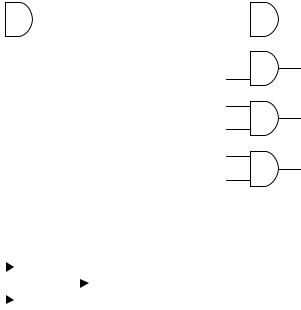
Two VHDL codes are presented below. Both perform the AND operation between the input signals and assign the result to the output signal. The only di¤erence between them is the number of bits in the input and output ports (one bit in the first, four bits in the second). The circuits inferred from these codes are shown in figure 3.2.
---------------------------- |
----------------------------------- |
ENTITY and2 IS |
ENTITY and2 IS |
PORT (a, b: IN BIT; |
PORT (a, b: IN BIT_VECTOR (0 TO 3); |
x: OUT BIT); |
x: OUT BIT_VECTOR (0 TO 3)); |
END and2; |
END and2; |
---------------------------- |
----------------------------------- |
ARCHITECTURE and2 OF and2 IS |
ARCHITECTURE and2 OF and2 IS |
BEGIN |
BEGIN |
x <= a AND b; |
x <= a AND b; |
END and2; |
END and2; |
---------------------------- |
----------------------------------- |
Example 3.3: Adder
Figure 3.3 shows the top-level diagram of a 4-bit adder. The circuit has two inputs (a, b) and one output (sum). Two solutions are presented. In the first, all signals are of type SIGNED, while in the second the output is of type INTEGER. Notice in solution 2 that a conversion function was used in line 13, for the type of a þ b does not match that of sum. Notice also the inclusion of the std_logic_arith package (line 4 of each solution), which specifies the SIGNED data type. Recall that a SIGNED value is represented like a vector; that is, similar to STD_LOGIC_VECTOR, not like an INTEGER.
TLFeBOOK
42 |
Chapter 3 |
1 ----- Solution 1: in/out=SIGNED ----------
2LIBRARY ieee;
3 USE ieee.std_logic_1164.all;
4 USE ieee.std_logic_arith.all;
5 ------------------------------------------
6ENTITY adder1 IS
7PORT ( a, b : IN SIGNED (3 DOWNTO 0);
8 |
sum : OUT SIGNED (4 DOWNTO 0)); |
9 |
END adder1; |
10 |
------------------------------------------ |
11 |
ARCHITECTURE adder1 OF adder1 IS |
12BEGIN
13sum <= a + b;
14END adder1;
15 ------------------------------------------
a |
|
|
|
x |
a(0) |
|
|
|
x(0) |
|
|
||||||||
b |
|
|
|
b(0) |
|
|
|
||
|
|
|
|
||||||
|
|
|
|
|
|
|
|
||
|
|
||||||||
|
|
|
|
|
a(1) |
|
|
||
|
|
|
|
|
|
||||
x(1)
b(1)
a(2)
x(2)
b(2)
a(3)
x(3)
b(3)
Figure 3.2
Circuits inferred from the codes of example 3.2.
a (3:0) |
|
|
+ |
|
sum (4:0) |
|
|
||||||
|
|
|
||||
|
|
|||||
b (3:0) |
|
|
|
|
|
|
|
|
|||||
|
|
|
|
|||
Figure 3.3 |
|
|||||
4-bit adder of example 3.3. |
|
|||||
TLFeBOOK
Data Types |
43 |
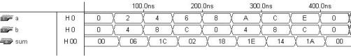
Figure 3.4
Simulation results of example 3.3.
1 ------ Solution 2: out=INTEGER -----------
2LIBRARY ieee;
3 USE ieee.std_logic_1164.all;
4 USE ieee.std_logic_arith.all;
5 ------------------------------------------
6ENTITY adder2 IS
7PORT ( a, b : IN SIGNED (3 DOWNTO 0);
8 |
sum : OUT INTEGER RANGE -16 TO 15); |
9 |
END adder2; |
10 |
------------------------------------------ |
11 |
ARCHITECTURE adder2 OF adder2 IS |
12BEGIN
13sum <= CONV_INTEGER(a + b);
14END adder2;
15 ------------------------------------------
Simulation results (for either solution) are presented in figure 3.4. Notice that the numbers are represented in hexadecimal 2’s complement form. Since the input range is from 8 to 7, its representation is 7 ! 7, 6 ! 6, . . . , 0 ! 0, 1 ! 15, 2 ! 14,
. . . , 8 ! 8. Likewise, the output range is from 16 to 15, so its representation is 15 ! 15, . . . , 0 ! 0, 1 ! 31, . . . , 16 ! 16. Therefore, 2H þ 4H ¼ 06H (that is, 2 þ 4 ¼ 6), 4H þ 8H ¼ 1CH (that is, 4 þ ( 8) ¼ 4), etc., where H ¼ Hexadecimal.
3.11Problems
The problems below are based on the following TYPE definitions and SIGNAL declarations:
TYPE array1 IS ARRAY (7 DOWNTO 0) OF STD_LOGIC;
TYPE array2 IS ARRAY (3 DOWNTO 0, 7 DOWNTO 0) OF STD_LOGIC; TYPE array3 IS ARRAY (3 DOWNTO 0) OF array1;
TLFeBOOK
44 |
Chapter 3 |
SIGNAL a : BIT;
SIGNAL b : STD_LOGIC;:
SIGNAL x : array1;
SIGNAL y : array2;
SIGNAL w : array3;
SIGNAL z : STD_LOGIC_VECTOR (7 DOWNTO 0);
Problem 3.1
Determine the dimensionality (scalar, 1D, 2D, or 1Dx1D) of the signals given. Also, write down a numeric example for each signal.
Problem 3.2
Determine which among the assignments in table P3.2 are legal and which are illegal. Briefly justify your answers. Also, determine the dimensionality of each assignment (on both sides).
Problem 3.3: Subtypes
Consider the pre-defined data types INTEGER and STD_LOGIC_VECTOR. Consider also the user-defined types ARRAY1 and ARRAY2 specified above. For each, write down a possible SUBTYPE.
Problem 3.4: ROM
Consider the implementation of a ROM (read-only memory). It can be done utilizing a 1Dx1D CONSTANT. Say that the ROM must be organized as a pile of eight words of four bits each. Create an array called rom, then define a signal of type rom capable of solving this problem. Choose the values to be stored in the ROM and declare them along with your CONSTANT, that is, ‘‘CONSTANT my_rom: rom :=(values);’’.
Problem 3.5: Simple Adder
Rewrite solution 1 of example 3.3, but this time with all input and output signals of type STD_LOGIC_VECTOR. (Suggestion: review section 3.8).
TLFeBOOK

Data Types |
45 |
Table P3.2
|
|
Dimension |
Legal or illegal |
Assignment |
(on each side) |
(why) |
|
|
|
|
|
a <= x(2); |
|
|
|
b <= x(2); |
|
|
|
b <= y(3,5); |
|
|
|
b <= w(5)(3); |
|
|
|
y(1)(0) <= z(7); |
|
|
|
x(0) |
<= y(0,0); |
|
|
x <= |
"1110000"; |
|
|
a <= |
"0000000"; |
|
|
y(1) |
<= x; |
|
|
w(0) |
<= y; |
|
|
w(1) |
<= (7=>'1', OTHERS=>'0'); |
|
|
y(1) |
<= (0=>'0', OTHERS=>'1'); |
|
|
w(2)(7 DOWNTO 0) <= x;
w(0)(7 DOWNTO 6) <= z(5 DOWNTO 4); x(3) <= x(5 DOWNTO 5);
b <= x(5 DOWNTO 5);
y <= ((OTHERS=>'0'), (OTHERS=>'0'), (OTHERS=>'0'), "10000001");
z(6) <= x(5);
z(6 DOWNTO 4) <= x(5 DOWNTO 3); z(6 DOWNTO 4) <= y(5 DOWNTO 3); y(6 DOWNTO 4) <= z(3 TO 5); y(0, 7 DOWNTO 0) <= z;
w(2,2) <= '1';
TLFeBOOK
TLFeBOOK