

CodeVisionAVR
5.6 Setting the UART or USART
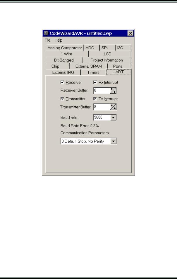
By selecting the UART tab of the CodeWizardAVR, you can specify the UART configuration.
Checking the Receiver check box activates the UART receiver.
The receiver can function in the following modes:
•polled, the Rx Interrupt check box isn't checked
•interrupt driven circular buffer, the Rx Interrupt check box is checked.
In the interrupt driven mode you can specify the size of the circular buffer using the Receiver Buffer spinedit box.
Checking the Transmitter check box activates the UART transmitter.
The transmitter can function in the following modes:
•polled, the Tx Interrupt check box isn't checked
•interrupt driven circular buffer, the Tx Interrupt check box is checked.
In the interrupt driven mode you can specify the size of the circular buffer using the Transmitter Buffer spinedit box.
The communication Baud rate can be specified using the UART Baud Rate list box. CodeWizardAVR will automatically set the UBRR according to the Baud rate and AVR chip clock frequency. The Baud rate error for these parameters will be calculated and displayed.
The Communications Parameters list box allows you to specify the number of data bits, stop bits and parity used for serial communication.
© 1998-2007 HP InfoTech S.R.L. |
Page 192 |

CodeVisionAVR
For devices featuring an USART there will be an additional Mode list box.
It allows you to specify the following communication modes:
•Asynchronous
•Synchronous Master, with the UCSRC register's UCPOL bit set to 0
•Synchronous Master, with the UCSRC register's UCPOL bit set to 1
•Synchronous Slave, with the UCSRC register's UCPOL bit set to 0
•Synchronous Slave, with the UCSRC register's UCPOL bit set to 1.
The serial communication is realized using the Standard Input/Output Functions getchar, gets, scanf, putchar, puts and printf.
For interrupt driven serial communication, CodeWizardAVR automatically redefines the basic getchar and putchar functions.
The receiver buffer is implemented using the global array rx_buffer.
The global variable rx_wr_index is the rx_buffer array index used for writing received characters in the buffer.
The global variable rx_rd_index is the rx_buffer array index used for reading received characters from the buffer by the getchar function.
The global variable rx_counter contains the number of characters received in rx_buffer and not yet read by the getchar function.
If the receiver buffers overflows the rx_buffer_overflow global bit variable will be set.
© 1998-2007 HP InfoTech S.R.L. |
Page 193 |

CodeVisionAVR
The transmitter buffer is implemented using the global array tx_buffer.
The global variable tx_wr_index is the tx_buffer array index used for writing in the buffer the characters to be transmitted.
The global variable tx_rd_index is the tx_buffer array index used for reading from the buffer the characters to be transmitted by the putchar function.
The global variable tx_counter contains the number of characters from tx_buffer not yet transmitted by the interrupt system.
For devices with 2 UARTs, respectively 2 USARTs, there will be two tabs present: UART0 and
UART1, respectively USART0 and USART1.
The functions of configuration check and list boxes will be the same as described above.
The UART0 (USART0) will use the normal putchar and getchar functions.
In case of interrupt driven buffered communication, UART0 (USART0) will use the following variables: rx_buffer0, rx_wr_index0, rx_rd_index0, rx_counter0, rx_buffer_overflow0,
tx_buffer0, tx_wr_index0, tx_rd_index0, tx_counter0.
The UART1 (USART1) will use the putchar1 and getchar1 functions.
In case of interrupt driven buffered communication, UART1 (USART1) will use the following variables: rx_buffer1, rx_wr_index1, rx_rd_index1, rx_counter1, rx_buffer_overflow1,
tx_buffer1, tx_wr_index1, tx_rd_index1, tx_counter1.
All serial I/O using functions declared in stdio.h, will be done using UART0 (USART0).
© 1998-2007 HP InfoTech S.R.L. |
Page 194 |

CodeVisionAVR
5.7 Setting the Analog Comparator
By selecting the Analog Comparator tab of the CodeWizardAVR, you can specify the analog comparator configuration.
Checking the Analog Comparator Enabled check box enables the on-chip analog comparator. Checking the Bandgap Voltage Reference check box will connect an internal voltage reference to the analog comparator's positive input.
Checking the Input Multiplexer check box will connect the ADCs analog multiplexer to the analog comparator's negative input.
If you want to generate interrupts if the analog comparator's output changes state, then you must check the Analog Comparator Interrupt check box.
The type of output change that triggers the interrupt can be specified in the Analog Comparator Interrupt Mode settings.
If the analog comparator's output is to be used for capturing the state of timer/counter 1 then the
Analog Comparator Input Capture check box must be checked.
The Disable Digital Input Buffer on AIN0, respectively Disable Digital Input Buffer on AIN1 check boxes, if checked, will deactivate the digital input buffers on the AIN0, respectively AIN1 pins, thus reducing the power consumption of the chip.
The corresponding bits in the PIN registers will always read 0 in this case. Some of this check boxes may not be present on all the AVR chips.
If the analog comparator interrupt is enabled, the CodeWizardAVR will define the ana_comp_isr interrupt service routine.
© 1998-2007 HP InfoTech S.R.L. |
Page 195 |