


CodeVisionAVR
3.14 Accessing the EEPROM
Accessing the AVR internal EEPROM is accomplished using global variables, preceded by the keyword eeprom.
Example:
/* The value 1 is stored in the EEPROM during chip programming */ eeprom int alfa=1;
eeprom char beta; eeprom long array1[5];
/* The string is stored in the EEPROM during chip programming */ eeprom char string[]=”Hello”;
void main(void) { int i;
/* Pointer to EEPROM */ int eeprom *ptr_to_eeprom;
/* Write directly the value 0x55 to the EEPROM */ alfa=0x55;
/* or indirectly by using a pointer */ ptr_to_eeprom=&alfa; *ptr_to_eeprom=0x55;
/* Read directly the value from the EEPROM */ i=alfa;
/* or indirectly by using a pointer */ i=*ptr_to_eeprom;
}
Pointers to the EEPROM always use 16 bits.
© 1998-2007 HP InfoTech S.R.L. |
Page 96 |

CodeVisionAVR
3.15 Using Interrupts
The access to the AVR interrupt system is implemented with the interrupt keyword. Example:
/* Vector numbers are for the AT90S8515 */
/* Called automatically on external interrupt */ interrupt [2] void external_int0(void) {
/* Place your code here */
}
/* Called automatically on TIMER0 overflow */ interrupt [8] void timer0_overflow(void) { /* Place your code here */
}
Interrupt vector numbers start with 1.
The compiler will automatically save the affected registers when calling the interrupt functions and restore them back on exit.
A RETI assembly instruction is placed at the end of the interrupt function. Interrupt functions can’t return a value nor have parameters.
You must also set the corresponding bits in the peripheral control registers to configure the interrupt system and enable the interrupts.
The automatic saving and restoring of registers affected by the interrupt handler, can be turned on or off using the #pragma savereg directive.
Example:
/* Turn registers saving off */ #pragma savereg-
/* interrupt handler */ interrupt [1] void my_irq(void) {
/* now save only the registers that are affected by the routines in the interrupt handler, for example R30, R31 and SREG */
#asm
push r30 push r31
in r30,SREG push r30
#endasm
/* place the C code here */ /* .... */
/* now restore SREG, R31 and R30 */ #asm
pop r30
out SREG,r30 pop r31
pop r30 #endasm
}
/* re-enable register saving for the other interrupts */ #pragma savereg+
© 1998-2007 HP InfoTech S.R.L. |
Page 97 |

CodeVisionAVR
The default state is automatic saving of registers during interrupts.
The #pragma savereg directive is maintained only for compatibility with versions of the compiler prior to V1.24.1. This directive is not recommended for new projects.
© 1998-2007 HP InfoTech S.R.L. |
Page 98 |
CodeVisionAVR
3.16 SRAM Memory Organization
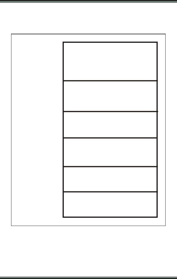
A compiled program has the following memory map:
0
20h
60h (or 100h)
60h (or 100h)+ Data Stack Size
60h (or 100h)+ Data Stack Size+ Global Var. Size
_HEAP_START_
SRAM End
Working Registers
I/O Registers
DSTACKEND
Data Stack
Y initial value
Global Variables
HSTACKEND Hardware Stack SP initial value
Heap
The Working Registers area contains 32x8 bit general purpose working registers.
The compiler uses the following registers: R0, R1, R15, R22, R23, R24, R25, R26, R27, R28, R29, R30 and R31.
Also some of the registers from R2 to R15 may be allocated by the compiler for global and local bit variables. The rest of unused registers, in this range, are allocated for global char and int variables and global pointers.
Registers R16 to R21 are allocated for local char and int variables.
© 1998-2007 HP InfoTech S.R.L. |
Page 99 |
CodeVisionAVR
The I/O Registers area contains 64 addresses for the CPU peripheral functions as Port Control Registers, Timer/Counters and other I/O functions. You may freely use these registers in your assembly programs.
The Data Stack area is used to dynamically store local variables, passing function parameters and saving registers R0, R1, R15, R22, R23, R24, R25, R26, R27, R30, R31 and SREG during interrupt routine servicing.
The Data Stack Pointer is implemented using the Y register.
At start-up the Data Stack Pointer is initialized with the value 5Fh (or FFh for some chips)+Data Stack Size.
When saving a value in the Data Stack, the Data Stack Pointer decrements. When the value is retrieved, the Data Stack Pointer is incremented back.
When configuring the compiler, in the Project|Configure|C Compiler|Code Generation menu, you must specify a sufficient Data Stack Size, so it will not overlap the I/O Register area during program execution.
The Global Variables area is used to statically store the global variables during program execution. The size of this area can be computed by summing the size of all the declared global variables.
The Hardware Stack area is used for storing the functions return addresses.
The SP register is used as a stack pointer and is initialized at start-up with value of the
_HEAP_START_ -1 address.
During the program execution the Hardware Stack grows downwards to the Global Variables area.
When configuring the compiler you have the option to place the strings DSTACKEND, respectively
HSTACKEND, at the end of the Data Stack, respectively Hardware Stack areas.
When you debug the program with AVR Studio you may see if these strings are overwritten, and consequently modify the Data Stack Size using the Project|Configure|C Compiler|Code Generation menu command.
When your program runs correctly, you may disable the placement of the strings in order to reduce code size.
The Heap is a memory area located between the Hardware Stack and the SRAM end.
It is used by the memory allocation functions from the Standard Library: malloc, calloc, realloc and free.
The Heap size must be specified in the Project|Configure|C Compiler|Code Generation menu. It can be calculated using the following formulae:
heap _ size =(n +1) 4 +∑n block _ sizei
i=1
where: n is the number of memory blocks that will be allocated in the Heap block _ sizei is the size of the memory block i
If the memory allocation functions will not be used, then the Heap size must be specified as zero.
© 1998-2007 HP InfoTech S.R.L. |
Page 100 |