

CodeVisionAVR
5.5 Setting the Timers/Counters
By selecting the Timers tab of the CodeWizardAVR, you can specify the timers/counters configuration.
A number of Timer tabs will be displayed according to the AVR chip type.
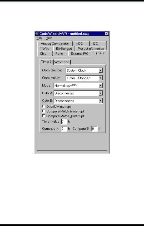
By selecting the Timer 0 tab you can have the following options:
•Clock Source specifies the timer/counter 0 clock pulse source
•Clock Value specifies the timer/counter 0 clock frequency
•Mode specifies if the timer/counter 0 functioning mode
•Outp. A specifies the function of the timer/counter 0 compare A output and depends of the functioning mode
•Outp. B specifies the function of the timer/counter 0 compare B output and depends of the functioning mode
•Overflow Interrupt specifies if an interrupt is to be generated on timer/counter 0 overflow
•Compare Match A Interrupt specifies if an interrupt is to be generated on timer/counter 0 compare A match
•Compare Match B Interrupt specifies if an interrupt is to be generated on timer/counter 0 compare B match
•Timer Value specifies the initial value of timer/counter 0 at startup
•Compare A specifies the initial value of timer/counter 0 output compare A register
•Compare B specifies the initial value of timer/counter 0 output compare B register.
© 1998-2007 HP InfoTech S.R.L. |
Page 187 |
CodeVisionAVR
If timer/counter 0 interrupts are used the following interrupt service routines may be defined by the CodeWizardAVR:
•timer0_ovf_isr for timer/counter overflow
•timer0_compa_isr for timer/counter output compare A match
•timer0_compb_isr for timer/counter output compare B match
You must note that depending of the used AVR chip some of these options may not be present. For more information you must consult the corresponding Atmel data sheet.
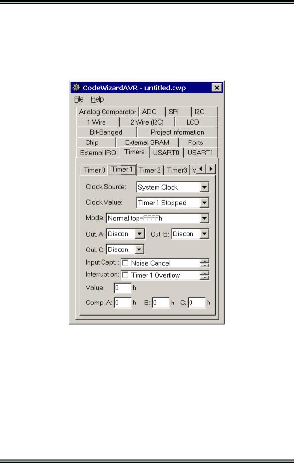
By selecting the Timer 1 tab you can have the following options:
•Clock Source specifies the timer/counter 1 clock pulse source
•Clock Value specifies the timer/counter 1 clock frequency
•Mode specifies if the timer/counter 1 functioning mode
•Out. A specifies the function of the timer/counter 1 output A and depends of the functioning mode
•Out. B specifies the function of the timer/counter 1 output B and depends of the functioning mode
•Out. C specifies the function of the timer/counter 3 output C and depends of the functioning mode
•Inp Capt. specifies the timer/counter 1 capture trigger edge and if the noise canceler is to be used
•Interrupt on specifies if an interrupt is to be generated on timer/counter 1 overflow, input capture and compare match
•Timer Value specifies the initial value of timer/counter 1 at startup
•Comp. A, B and C specifies the initial value of timer/counter 1 output compare registers A, B and
C.
© 1998-2007 HP InfoTech S.R.L. |
Page 188 |
CodeVisionAVR
If timer/counter 1 interrupts are used the following interrupt service routines may be defined by the CodeWizardAVR:
•timer1_ovf_isr for timer/counter overflow
•timer1_comp_isr or timer1_compa_isr, timer1_compb_isr and timer1_copmc_isr for timer/counter output compare match
•timer1_capt_isr for timer/counter input capture
You must note that depending of the used AVR chip some of these options may not be present. For more information you must consult the corresponding Atmel data sheet.
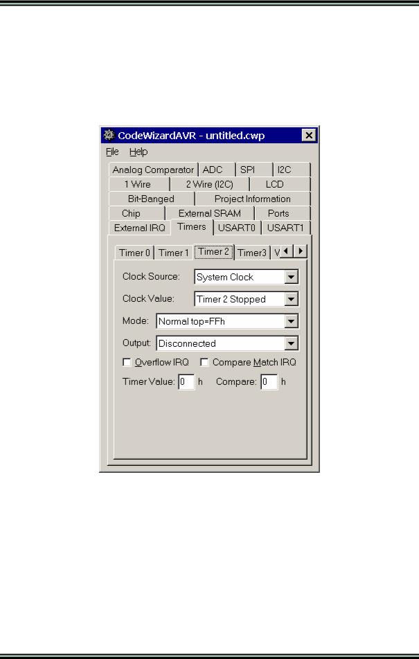
By selecting the Timer 2 tab you can have the following options:
•Clock Source specifies the timer/counter 2 clock pulse source
•Clock Value specifies the timer/counter 2 clock frequency
•Mode specifies if the timer/counter 2 functioning mode
•Output specifies the function of the timer/counter 2 output and depends of the functioning mode
•Overflow IRQ specifies if an interrupt is to be generated on timer/counter 2 overflow
•Compare Match IRQ specifies if an interrupt is to be generated on timer/counter 2 compare match
•Timer Value specifies the initial value of timer/counter 2 at startup
•Compare specifies the initial value of timer/counter 2 output compare register.
© 1998-2007 HP InfoTech S.R.L. |
Page 189 |
CodeVisionAVR
If timer/counter 2 interrupts are used the following interrupt service routines may be defined by the CodeWizardAVR:
•timer2_ovf_isr for timer/counter overflow
•timer2_comp_isr for timer/counter output compare match.
You must note that depending of the used AVR chip some of these options may not be present. For more information you must consult the corresponding Atmel data sheet.
By selecting the Timer 3 tab you can have the following options:
•Clock Source specifies the timer/counter 3 clock pulse source
•Clock Value specifies the timer/counter 3 clock frequency
•Mode specifies if the timer/counter 3 functioning mode
•Out. A specifies the function of the timer/counter 3 output A and depends of the functioning mode
•Out. B specifies the function of the timer/counter 3 output B and depends of the functioning mode
•Out. C specifies the function of the timer/counter 3 output C and depends of the functioning mode
•Inp Capt. specifies the timer/counter 3 capture trigger edge and if the noise canceler is to be used
•Interrupt on specifies if an interrupt is to be generated on timer/counter 3 overflow, input capture and compare match
•Timer Value specifies the initial value of timer/counter 3 at startup
•Comp. A, B and C specifies the initial value of timer/counter 3 output compare registers A, B and
C.
© 1998-2007 HP InfoTech S.R.L. |
Page 190 |
CodeVisionAVR
If timer/counter 1 interrupts are used the following interrupt service routines may be defined by the CodeWizardAVR:
•timer1_ovf_isr for timer/counter overflow
•timer1_comp_isr or timer1_compa_isr, timer1_compb_isr and timer1_copmc_isr for timer/counter output compare match
•timer1_capt_isr for timer/counter input capture
You must note that depending of the used AVR chip some of these options may not be present. For more information you must consult the corresponding Atmel data sheet.
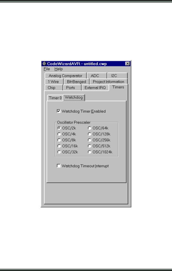
By selecting the Watchdog tab you can configure the watchdog timer.
Checking the Watchdog Timer Enabled check box activates the watchdog timer. You will have then the possibility to set the watchdog timer's Oscillator Prescaller.
If the Watchdog Timeout Interrupt check box is checked, an interrupt will be generated instead of reset if a timeout occurs.
In case the watchdog timer is enabled, you must include yourself the appropriate code sequences to reset it periodically. Example:
#asm("wdr")
For more information about the watchdog timer you must consult the Atmel data sheet for the chip that you use.
© 1998-2007 HP InfoTech S.R.L. |
Page 191 |