
- •Table of Contents
- •1. Introduction
- •2. CodeVisionAVR Integrated Development Environment
- •2.1 Working with Files
- •2.1.1 Creating a New File
- •2.1.2 Opening an Existing File
- •2.1.3 Files History
- •2.1.4 Editing a File
- •2.1.5 Saving a File
- •2.1.6 Renaming a File
- •2.1.7 Printing a File
- •2.1.8 Closing a File
- •2.1.9 Using the Navigator
- •2.1.10 Using Code Templates
- •2.1.11 Using Clipboard History
- •2.2 Working with Projects
- •2.2.1 Creating a New Project
- •2.2.2 Opening an Existing Project
- •2.2.3 Adding Notes or Comments to the Project
- •2.2.4 Configuring the Project
- •2.2.4.1 Adding or removing a File from the Project
- •2.2.4.2 Setting the C Compiler Options
- •2.2.4.3 Executing an User Specified Program before Make
- •2.2.4.4 Transferring the Compiled Program to the AVR Chip after Make
- •2.2.4.5 Executing an User Specified Program after Make
- •2.2.5 Obtaining an Executable Program
- •2.2.5.1 Checking the Project for Syntax Errors
- •2.2.5.2 Compiling the Project
- •2.2.5.3 Making the Project
- •2.2.6 Closing a Project
- •2.3 Tools
- •2.3.1 The AVR Studio Debugger
- •2.3.2 The AVR Chip Programmer
- •2.3.3 The Serial Communication Terminal
- •2.3.4 Executing User Programs
- •2.3.4.1 Configuring the Tools Menu
- •2.4 IDE Settings
- •2.4.1 The View Menu
- •2.4.2 Configuring the Editor
- •2.4.3 Configuring the Assembler
- •2.4.4 Setting the Debugger Path
- •2.4.5 AVR Chip Programmer Setup
- •2.4.6 Serial Communication Terminal Setup
- •2.5 Accessing the Help
- •2.6 Transferring the License to another computer
- •2.7 Connecting to HP InfoTech's Web Site
- •2.8 Contacting HP InfoTech by E-Mail
- •2.9 Quitting the CodeVisionAVR IDE
- •3. CodeVisionAVR C Compiler Reference
- •3.1 The Preprocessor
- •3.2 Comments
- •3.3 Reserved Keywords
- •3.4 Identifiers
- •3.5 Data Types
- •3.6 Constants
- •3.7 Variables
- •3.7.1 Specifying the SRAM Storage Address for Global Variables
- •3.7.2 Bit Variables
- •3.7.3 Allocation of Variables to Registers
- •3.7.4 Structures
- •3.7.5 Unions
- •3.7.6 Enumerations
- •3.7.7 Global Variables Memory Map File
- •3.8 Defining Data Types
- •3.9 Type Conversions
- •3.10 Operators
- •3.11 Functions
- •3.12 Pointers
- •3.13 Accessing the I/O Registers
- •3.13.1 Bit level access to the I/O Registers
- •3.14 Accessing the EEPROM
- •3.15 Using Interrupts
- •3.16 SRAM Memory Organization
- •3.17 Using an External Startup File
- •3.18 Including Assembly Language in Your Program
- •3.18.1 Calling Assembly Functions from C
- •3.19 Creating Libraries
- •3.20 Using the AVR Studio Debugger
- •3.20.1 Using the AVR Studio Debugger version 3
- •3.20.2 Using the AVR Studio Debugger version 4.06 or later
- •3.21 Hints
- •3.22 Limitations
- •4. Library Functions Reference
- •4.1 Character Type Functions
- •4.2 Standard C Input/Output Functions
- •4.3 Standard Library Functions
- •4.4 Mathematical Functions
- •4.5 String Functions
- •4.6 Variable Length Argument Lists Macros
- •4.7 Non-local Jump Functions
- •4.8 BCD Conversion Functions
- •4.9 Gray Code Conversion Functions
- •4.10 Memory Access Functions
- •4.11 LCD Functions
- •4.11.1 LCD Functions for displays with up to 2x40 characters
- •4.11.2 LCD Functions for displays with 4x40 characters
- •4.11.3 LCD Functions for displays connected in 8 bit memory mapped mode
- •4.12 I2C Bus Functions
- •4.12.3 Philips PCF8563 Real Time Clock Functions
- •4.12.4 Philips PCF8583 Real Time Clock Functions
- •4.14 1 Wire Protocol Functions
- •4.14.3 Maxim/Dallas Semiconductor DS2430 EEPROM Functions
- •4.14.4 Maxim/Dallas Semiconductor DS2433 EEPROM Functions
- •4.15 SPI Functions
- •4.16 Power Management Functions
- •4.17 Delay Functions
- •5. CodeWizardAVR Automatic Program Generator
- •5.1 Setting the AVR Chip Options
- •5.2 Setting the External SRAM
- •5.3 Setting the Input/Output Ports
- •5.4 Setting the External Interrupts
- •5.5 Setting the Timers/Counters
- •5.6 Setting the UART or USART
- •5.7 Setting the Analog Comparator
- •5.8 Setting the Analog-Digital Converter
- •5.9 Setting the ATmega406 Voltage Reference
- •5.10 Setting the ATmega406 Coulomb Counter
- •5.11 Setting the SPI Interface
- •5.12 Setting the Universal Serial Interface - USI
- •5.13 Setting the I2C Bus
- •5.13.1 Setting the LM75 devices
- •5.13.2 Setting the DS1621 devices
- •5.13.3 Setting the PCF8563 devices
- •5.13.4 Setting the PCF8583 devices
- •5.13.5 Setting the DS1307 devices
- •5.14 Setting the 1 Wire Bus
- •5.15 Setting the 2 Wire Bus
- •5.16 Setting the CAN Controller
- •5.17 Setting the ATmega169/329/3290/649/6490 LCD Controller
- •5.18 Setting the LCD
- •5.19 Setting the USB Controller
- •5.20 Setting Bit-Banged Peripherals
- •5.21 Specifying the Project Information
- •6. License Agreement
- •6.1 Software License
- •6.2 Liability Disclaimer
- •6.3 Restrictions
- •6.4 Operating License
- •6.5 Back-up and Transfer
- •6.6 Terms
- •6.7 Other Rights and Restrictions
- •7. Technical Support
- •8. Contact Information

CodeVisionAVR
2.4.5 AVR Chip Programmer Setup
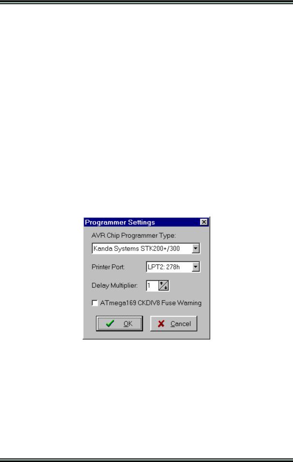
Using the Settings|Programmer menu command, you can select the type of the in-system programmer that is used, and the computer's port to which the programmer is connected. The current version of CodeVisionAVR supports the following in-system programmers:
•Kanda Systems STK200+ and STK300
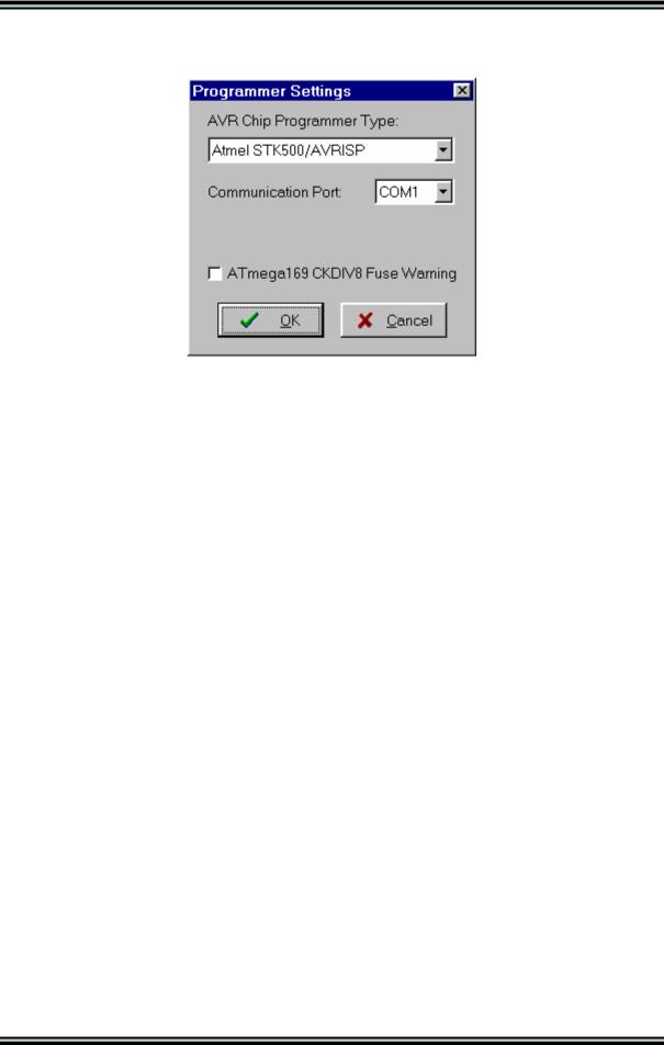
•Atmel STK500 and AVRISP (serial connection)
•Atmel AVRISP MkII (USB connection)
•Atmel AVR Dragon (USB connection)
•Atmel JTAGICE MkII (USB connection)
•Atmel AVRProg (AVR910 application note)
•Dontronics DT006
•Vogel Elektronik VTEC-ISP
•Futurlec JRAVR
•MicroTronics ATCPU and Mega2000
The STK200+, STK300, DT006, VTEC-ISP, JRAVR, ATCPU and Mega2000 in-system programmers use the parallel printer port.
The following choices are available through the Printer Port radio group box:
•LPT1, at base address 378h;
•LPT2, at base address 278h;
•LPT3, at base address 3BCh.
The Delay Multiplier value can be increased in case of programming problems on very fast machines. Of course this will increase overall programming time.
The Atmega169 CKDIV8 Fuse Warning check box, if checked, will enable the generation of a warning that further low voltage serial programming will be impossible for the Atmega169 Engineering Samples, if the CKDIV8 fuse will be programmed to 0.
For usual Atmega169 chips this check box must be left unchecked.
© 1998-2007 HP InfoTech S.R.L. |
Page 58 |

CodeVisionAVR
The STK500, AVRISP and AVRProg programmers use the RS232C serial communication port, which can be specified using the Communication Port list box.
The Atmel AVRISP MkII, AVR Dragon and JTAGICE MkII use the USB connection for communication with the PC.
Usage of this programmer requires the Atmel’s AVR Studio V4.13 or later software to be installed on the PC.
Changes can be saved, respectively canceled, using the OK, respectively Cancel buttons.
© 1998-2007 HP InfoTech S.R.L. |
Page 59 |

CodeVisionAVR
2.4.6 Serial Communication Terminal Setup
The serial communication Terminal is configured using the Settings|Terminal menu command.
In the Terminal Setup window you can select the:
•computer's communication port used by the Terminal: COM1 to COM6;
•Baud rate used for communication: 110 to 115200;
•number of data bits used in reception and transmission: 5 to 8;
•number of stop bits used in reception and transmission: 1, 1.5 or 2;
•parity used in reception and transmission: None, Odd, Even, Mark or Space;
•type of emulated terminal: TTY, VT52 or VT100;
•type of handshaking used in communication: None, Hardware (CTS or DTR) or Software (XON/XOFF);
•possibility to append LF characters after CR characters on reception and transmission;
•enabling or disabling the echoing of the transmitted characters
•number of character Rows and Columns in the Terminal window
•Font type used for displaying characters in the Terminal window.
Changes can be saved, respectively canceled, using the OK, respectively Cancel buttons.
© 1998-2007 HP InfoTech S.R.L. |
Page 60 |