

CodeVisionAVR
2.3 Tools
Using the Tools menu you can execute other programs without exiting the CodeVisionAVR IDE.
2.3.1 The AVR Studio Debugger
The CodeVisionAVR C Compiler is designed to work in conjunction with the Atmel AVR Studio debugger version 3 and 4.06 (or later).
For the AVR Studio debugger version 4.06 (or later) the compiler will generate an extended COFF object file that allows watching structures and unions. So it is highly recommended to use AVR Studio version 4.06 (or later) instead of version 3, which doesn’t support this feature. AVR Studio 4 prior to version 4.06 does not support the extended COFF object file format, so it can’t be used with CodeVisionAVR.
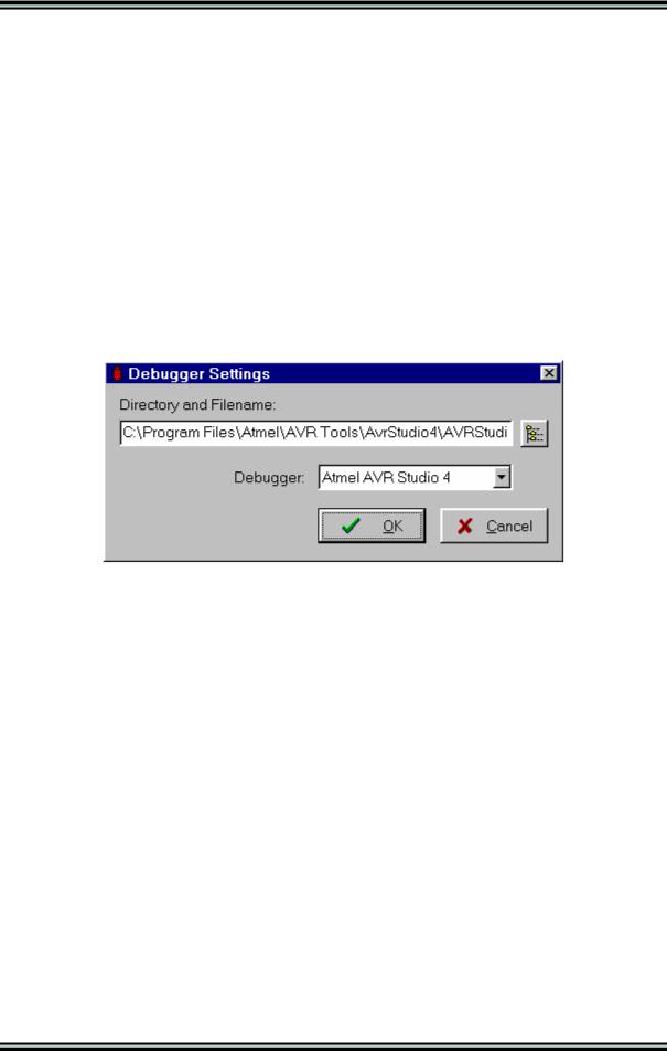
Before you can invoke the debugger, you must first specify its location and file name using the
Settings|Debugger menu command.
The AVR Studio version must be specified in the Debugger list box.
Changes can be saved, respectively canceled, using the OK, respectively Cancel buttons.
The debugger is executed by selecting the Tools|Debugger menu command or by pressing the Debugger button on the toolbar.
© 1998-2007 HP InfoTech S.R.L. |
Page 46 |
CodeVisionAVR
2.3.2 The AVR Chip Programmer
The CodeVisionAVR IDE has a built-in In-System AVR Chip Programmer that lets you easily transfer your compiled program to the microcontroller for testing.
The Programmer is designed to work with the Atmel STK500, AVRISP, AVRISP MkII, AVR Dragon, JTAGICE MkII, AVRProg (AVR910 application note), Kanda Systems STK200+, STK300, Dontronics DT006, Vogel Elektronik VTEC-ISP, Futurlec JRAVR or the MicroTronics ATCPU, Mega2000 development boards.
The type of the used programmer and the printer port can be selected by using the
Settings|Programmer menu command.
The Programmer is executed by selecting the Tools|Chip Programmer menu command or by pressing the Chip Programmer button on the toolbar.
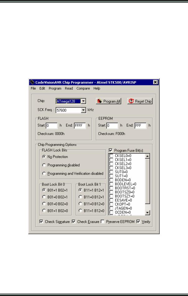
You can select the type of the chip you wish to program using the Chip combo box.
The SCK clock frequency used for In-System Programming with the STK500, AVRISP or AVRISP MkII can be specified using the SCK Freq. listbox. This frequency must not exceed ¼ of the chip’s clock frequency.
If the chip you have selected has Fuse Bit(s) that may be programmed, then a supplementary Program Fuse Bit(s) check box will appear.
If it is checked, than the chip’s Fuse Bit(s) will be programmed when the Program|All menu command is executed or when the Program All button is pressed.
© 1998-2007 HP InfoTech S.R.L. |
Page 47 |
CodeVisionAVR
The Fuse Bit(s) can set various chip options, which are described in the Atmel data sheets.
If a Fuse Bit(s) check box is checked, then the corresponding fuse bit will be set to 0, the fuse being considered as programmed (as per the convention from the Atmel data sheets).
If a Fuse Bits(s) check box is not checked, then the corresponding fuse bit will be set to 1, the fuse being considered as not programmed.
If you wish to protect your program from copying, you must select the corresponding option using the
FLASH Lock Bits radio box.
The Programmer has two memory buffers:
•The FLASH memory buffer
•The EEPROM memory buffer.
You can Load or Save the contents of these buffers using the File menu.
Supported file formats are:
•Atmel .rom and .eep
•Intel HEX
•Binary .bin
After loading a file in the corresponding buffer, the Start and End addresses are updated accordingly. You may also edit these addresses if you wish.
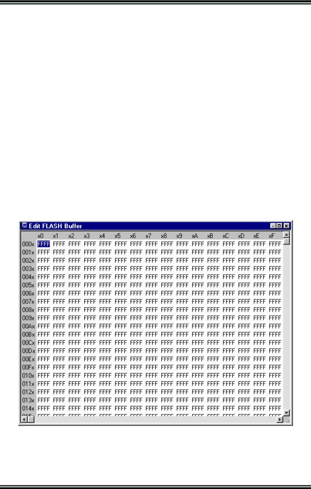
The contents of the FLASH, respectively EEPROM, buffers can be displayed and edited using the Edit|FLASH , respectively Edit|EEPROM menu commands.
When one of these commands is invoked, an Edit window displaying the corresponding buffer contents will open:
The buffer's contents, at the highlighted address, can be edited by pressing the F2 key and typing in the new value. The edited value is saved by pressing the Tab or arrow keys.
The highlighted address can be modified using the arrow, Tab, Shift+Tab, PageUp or PageDown keys.
© 1998-2007 HP InfoTech S.R.L. |
Page 48 |
CodeVisionAVR
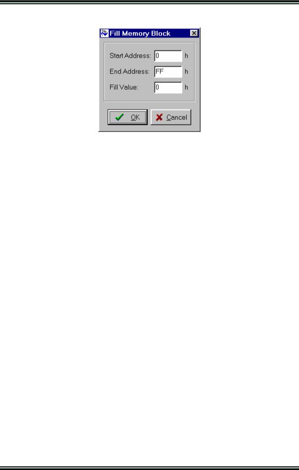
The Fill Memory Block window can be opened by right clicking in the Edit window:
This window lets you specify the Start Address, End Address and Fill Value of the memory area to be filled.
If you wish to check the chip's signature before any operation you must use the Check Signature option.
To speed up the programming process you can uncheck the Check Erasure check box. In this case there will be no verification of the correctness of the FLASH erasure.
The Preserve EEPROM checkbox allows preserving the contents of the EEPROM during chip erasure.
To speed up the programming process you also can uncheck the Verify check box.
In this case there will be no verification of the correctness of the FLASH and EEPROM programming.
For erasing a chip's FLASH and EEPROM you must select the Program|Erase menu command. After erasure the chip's FLASH and EEPROM are automatically blank checked.
For simple blank checking you must use the Program|Blank Check menu command.
If you wish to program the FLASH with the contents of the FLASH buffer you must use the
Program|FLASH menu command.
For programming the EEPROM you must use the Program|EEPROM menu command. After programming the FLASH and EEPROM are automatically verified.
To program the Lock, respectively the Fuse Bit(s) you must use the Program|Fuse Bit(s), respectively Program|Lock Bits menu commands.
The Program|All menu command allows to automatically:
•Erase the chip
•FLASH and EEPROM blank check
•Program and verify the FLASH
•Program and verify the EEPROM
•Program the Fuse and Lock Bits.
If you wish to read the contents of the chip's FLASH, respectively EEPROM, you must use the Read|FLASH, respectively Read|EEPROM menu commands.
For reading the chip's signature you must use the Read|Chip Signature menu command. To read the Lock, respectively the Fuse Bits you must use the Read|Lock Bits, respectively Read|Fuse Bits menu commands.
For some devices there's also the Read|Calibration Byte(s) option available.
It allows reading the value of the calibration bytes of the chip's internal RC oscillator.
© 1998-2007 HP InfoTech S.R.L. |
Page 49 |
CodeVisionAVR
If the programmer is an Atmel STK500, AVRISP, AVRISP MkII or AVRProg (AVR910 application note), then an additional menu command is present: Read|Programmer's Firmware Version. It allows reading the major and minor versions of the above mentioned programmers’ firmware.
For comparing the contents of the chip's FLASH, respectively EEPROM, with the corresponding memory buffer, you must use the Compare|FLASH, respectively Compare|EEPROM menu commands.
For exiting the Programmer and returning to the CodeVisionAVR IDE you must use the File|Close menu command.
© 1998-2007 HP InfoTech S.R.L. |
Page 50 |