


Lecture Notes: Introduction to Finite Element Method |
Chapter 1. Introduction |
||||
Solving the equations, we obtain the displacements |
|||||
u |
|
|
2P / k |
|
|
|
2 |
= |
|
1 |
|
u3 |
2P / k1 + P / k |
2 |
|||
and the reaction force
F1 = −2P
Checking the Results
•Deformed shape of the structure
•Balance of the external forces
•Order of magnitudes of the numbers
Notes About the Spring Elements
•Suitable for stiffness analysis
•Not suitable for stress analysis of the spring itself
•Can have spring elements with stiffness in the lateral direction, spring elements for torsion, etc.
© 1997-2003 Yijun Liu, University of Cincinnati |
19 |
Lecture Notes: Introduction to Finite Element Method |
Chapter 1. Introduction |
Example 1.1
k1 |
k2 |
P |
k3 |
|
1 |
2 |
3 |
4 |
x |
|
Given: |
For the spring system shown above, |
|
|||
|
k1 |
= 100 N / mm, k2 |
= 200 N / mm, k3 |
= 100 N / mm |
|
|
P = 500 N, |
u1 = u4 = 0 |
|
||
Find: |
(a) the global stiffness matrix |
|
|||
|
(b) displacements of nodes 2 and 3 |
|
|||
|
(c) the reaction forces at nodes 1 and 4 |
|
|||
|
(d) the force in the spring 2 |
|
|||
Solution: |
|
|
|
|
|
(a) The element stiffness matrices are |
|
||||
|
k1 |
100 |
−100 |
(N/mm) |
(1) |
|
= |
|
|||
|
|
−100 |
100 |
|
|
|
k2 |
200 |
−200 |
(N/mm) |
(2) |
|
= |
|
|||
|
|
−200 |
200 |
|
|
|
k3 |
100 |
−100 |
(N/mm) |
(3) |
|
= |
|
|||
|
|
−100 |
100 |
|
|
© 1997-2003 Yijun Liu, University of Cincinnati |
20 |
Lecture Notes: Introduction to Finite Element Method |
Chapter 1. Introduction |
Applying the superposition concept, we obtain the global stiffness matrix for the spring system as
|
u1 |
u2 |
u3 |
u4 |
|
100 |
−100 |
0 |
0 |
|
|
−100 |
100 +200 |
−200 |
0 |
|
|
K = |
0 |
−200 |
200 +100 |
|
|
|
−100 |
||||
|
0 |
0 |
−100 |
100 |
|
|
|
||||
or
100 |
−100 |
0 |
0 |
|
|
−100 |
300 |
−200 |
0 |
|
|
K = |
0 |
−200 |
300 |
|
|
|
−100 |
||||
|
0 |
0 |
−100 |
100 |
|
|
|
||||
which is symmetric and banded.
Equilibrium (FE) equation for the whole system is
100 |
−100 |
0 |
0 |
u |
|
F |
|
|
||||
|
−100 |
300 |
−200 |
0 |
|
1 |
|
|
1 |
|
|
|
|
|
u2 |
|
|
0 |
|
(4) |
|||||
0 |
−200 |
300 |
|
|
u |
|
= |
P |
|
|||
|
−100 |
|
|
|
|
|
||||||
|
|
|
|
|
|
3 |
|
|
||||
|
0 |
0 |
−100 |
100 |
u |
|
F |
|
|
|||
|
|
|
|
|
|
4 |
|
|
4 |
|
|
|
(b) Applying the BC (u1 = u4 = 0) in Eq(4), or deleting the 1st and 4th rows and columns, we have
© 1997-2003 Yijun Liu, University of Cincinnati |
21 |

Lecture Notes: Introduction to Finite Element Method |
Chapter 1. Introduction |
|
300 |
−200 u2 |
|
0 |
|
|
−200 |
300 |
u |
|
= P |
(5) |
|
|
|
|
3 |
|
|
|
Solving Eq.(5), we obtain
u |
|
|
P / 250 |
2 |
(mm) |
(6) |
2 |
|
= |
|
= |
||
u3 |
|
3P / 500 |
3 |
|
|
|
(c)From the 1st and 4th equations in (4), we get the reaction forces F1 = −100u2 = −200 (N)
F4 = −100u3 = −300 (N)
(d)The FE equation for spring (element) 2 is
|
200 |
−200 ui |
fi |
|||
|
|
200 |
|
|
= |
|
−200 |
uj |
f j |
||||
Here i = 2, j = 3 for element 2. Thus we can calculate the spring force as
F = f j = − fi = [−200 |
u |
|
200] 2 |
|
|
|
u3 |
|
= [−200 |
2 |
|
200] |
||
|
3 |
|
= 200 (N) |
|
|
Check the results!
© 1997-2003 Yijun Liu, University of Cincinnati |
22 |
Lecture Notes: Introduction to Finite Element Method |
Chapter 1. Introduction |
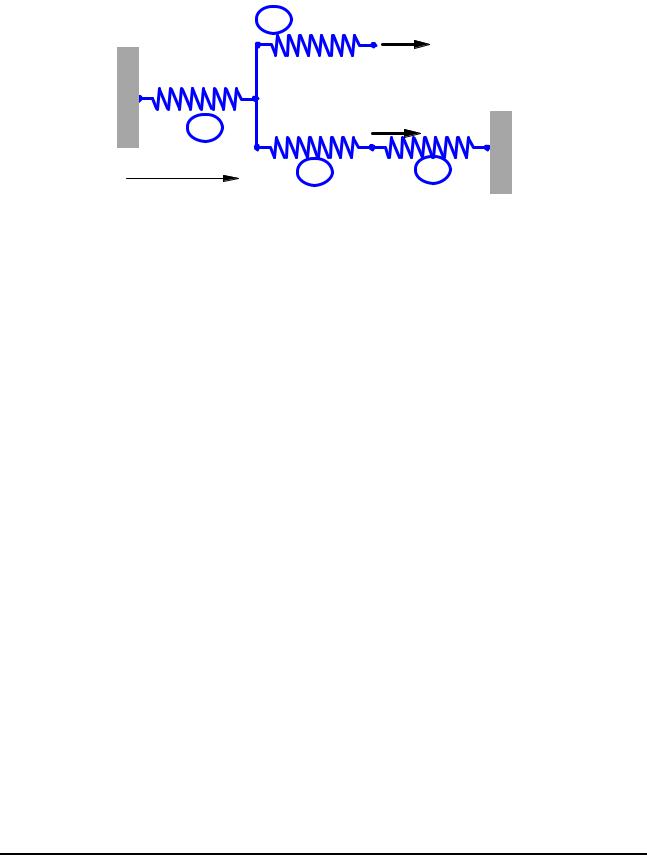
Example 1.2
|
4 |
k4 |
|
k1 |
|
4 |
2 |
k2 |
1 |
||
|
x |
2 |
|
|
F 1
1
F 2 k3
3 |
3 |
5 |
Problem: For the spring system with arbitrarily numbered nodes and elements, as shown above, find the global stiffness matrix.
Solution:
First we construct the following
Element Connectivity Table
Element |
Node i (1) |
Node j (2) |
|
|
|
1 |
4 |
2 |
2 |
2 |
3 |
3 |
3 |
5 |
4 |
2 |
1 |
|
|
|
which specifies the global node numbers corresponding to the local node numbers for each element.
© 1997-2003 Yijun Liu, University of Cincinnati |
23 |

Lecture Notes: Introduction to Finite Element Method Chapter 1. Introduction
Then we can write the element stiffness matrices as follows
|
|
u4 |
u2 |
|
|
|
u2 |
u3 |
|
|||
k1 |
|
k |
|
− k |
|
k2 |
|
k |
|
− k |
|
|
= |
|
1 |
1 |
|
= |
|
2 |
|
2 |
|
||
|
− k1 |
k1 |
|
− k2 |
k2 |
|||||||
|
|
u3 |
u5 |
|
|
|
u2 |
u1 |
|
||||
k3 |
|
k |
3 |
− k |
3 |
|
k4 |
|
k |
4 |
− k |
4 |
|
= |
|
|
|
= |
|
|
|
||||||
|
− k3 |
k3 |
|
− k4 |
k4 |
||||||||
Finally, applying the superposition method, we obtain the global stiffness matrix as follows
|
u1 |
|
|
|
u2 |
|
|
u3 |
|
u4 |
|
u5 |
|
|
k4 |
|
|
|
− k4 |
|
0 |
|
0 |
|
0 |
|
|||
− k |
4 |
k |
1 |
+ k |
2 |
+ k |
4 |
− k |
2 |
− k |
1 |
0 |
|
|
|
|
|
|
|
|
|
|
|
||||||
K = 0 |
|
|
|
− k2 |
|
k2 + k3 |
0 |
|
− k3 |
|
||||
|
0 |
|
|
|
− k1 |
|
0 |
|
k1 |
|
0 |
|
||
|
|
|
|
|
|
|
|
|||||||
|
0 |
|
|
|
0 |
|
|
− k3 |
0 |
|
k3 |
|
||
|
|
|
|
|
|
|
|
|||||||
The matrix is symmetric, banded, but singular.
© 1997-2003 Yijun Liu, University of Cincinnati |
24 |