


Lecture Notes: Introduction to Finite Element Method |
Chapter 5. Plate and Shell Elements |
Chapter 5. Plate and Shell Elements
I.Plate Theory
•Flat plate
•Lateral loading
•Bending behavior dominates
Note the following similarity:
1-D straight beam model Ù 2-D flat plate model
Applications:
•Shear walls
•Floor panels
•Shelves
•…
© 1997-2002 Yijun Liu, University of Cincinnati |
119 |
Lecture Notes: Introduction to Finite Element Method |
Chapter 5. Plate and Shell Elements |
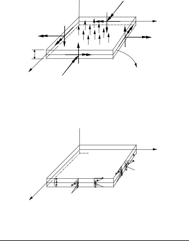
Forces and Moments Acting on the Plate:
 z
z
∆y
|
∆x |
|
|
y |
|
q(x,y) |
|
My |
|
|
|
|
||
|
|
|
|
|
|
|
|
Qy |
Mxy |
t |
|
|
|
|
|
|
Mx |
|
|
x |
|
Qx |
Mid surface |
|
|
|
|||
Mxy
Stresses:
 z
z


 τyz y
τyz y

 σy
σy
τxy
τxz |
σx |
τ |
|
xy |
|
|
|
x
© 1997-2002 Yijun Liu, University of Cincinnati |
120 |

Lecture Notes: Introduction to Finite Element Method |
Chapter 5. Plate and Shell Elements |
Relations Between Forces and Stresses
Bending moments (per unit length):
M x |
= ∫−t t/ |
/22σ x zdz , |
(N m / m) |
|
(1) |
|||||
M y |
= ∫−t t/ /22σ y zdz , |
(N m / m) |
|
(2) |
||||||
Twisting moment (per unit length): |
|
|
|
|
||||||
M xy = ∫−t t/ /22τxy zdz , |
(N m / m) |
|
(3) |
|||||||
Shear Forces (per unit length): |
|
|
|
|
||||||
Qx |
= ∫−t t/ /22τxz dz , |
|
|
(N / m) |
|
|
(4) |
|||
Qy |
= ∫−t t/ /22τ yz dz , |
|
|
(N / m) |
|
|
(5) |
|||
Maximum bending stresses: |
|
|
|
|
|
|||||
(σ x )max = ± |
6M |
x |
, |
(σ y )max = ± |
6M y |
. |
(6) |
|||
t2 |
|
|
t2 |
|||||||
|
|
|
|
|
|
|
|
|
||
•Maximum stress is always at z = ±t / 2
•No bending stresses at midsurface (similar to the beam model)
© 1997-2002 Yijun Liu, University of Cincinnati |
121 |
Lecture Notes: Introduction to Finite Element Method |
Chapter 5. Plate and Shell Elements |
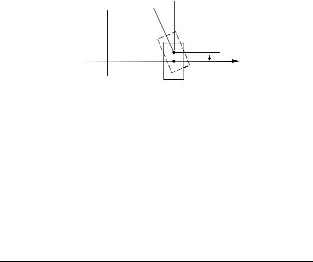
Thin Plate Theory ( Kirchhoff Plate Theory)
Assumptions (similar to those in the beam theory):
A straight line along the normal to the mid surface remains straight and normal to the deflected mid surface after loading, that is, these is no transverse shear deformation:
γ xz =γ yz = 0.
Displacement:
z 
∂w

 ∂x
∂x
 w
w
x
w = w(x, y), |
(deflection) |
||||
u = −z |
|
∂w |
, |
(7) |
|
|
|||||
|
|
∂x |
|
||
v = −z |
∂w |
. |
|
||
|
|
|
|||
|
|
∂y |
|
||
© 1997-2002 Yijun Liu, University of Cincinnati |
122 |

Lecture Notes: Introduction to Finite Element Method |
Chapter 5. Plate and Shell Elements |
Strains:
εx = −z ∂∂2 w ,
x2
ε y |
= −z |
∂ |
2 w |
, |
(8) |
|
∂y 2 |
||||||
|
|
|
|
|||
γ xy |
= −2z |
∂ 2 w |
. |
|||
∂x∂y |
||||||
|
|
|
|
|||
Note that there is no stretch of the mid surface due to the deflection (bending) of the plate.
Stresses (plane stress state):
σ x |
|
|
|
|
E |
1 |
||
|
|
|
|
= |
|
|
|
|
σ |
|
|
|
|
|
ν |
||
|
|
|
|
|||||
|
|
y |
|
1 |
−ν 2 |
|
||
τ |
xy |
|
|
|
|
|
0 |
|
|
|
|
|
|
|
|||
or,
σ x
σ y = −z 1−Eν 2τxy
ν |
0 |
|
εx |
|
1 |
0 |
|
εy , |
|
0 |
|
|
γ |
|
(1−ν) / 2 |
||||
|
|
|
|
xy |
1 |
ν |
0 |
ν |
1 |
0 |
|
0 |
(1−ν |
0 |
||
|
|
|
|
|
|
∂ |
2 w |
|
|||
|
|
|
∂x2 |
|
|
|
||
|
|
|
|
|
||||
|
|
|
∂ |
2 w |
|
|||
|
|
|
|
|
|
|
. |
(9) |
|
∂y2 |
|||||||
|
|
|
|
|
||||
) |
|
∂ |
2 |
|
|
|
||
|
|
|
|
w |
|
|||
|
|
|
|
|
|
|
|
|
|
|
|
|
|
|
|
||
|
|
∂x∂y |
|
|||||
Main variable: deflection w = w(x, y) .
© 1997-2002 Yijun Liu, University of Cincinnati |
123 |

Lecture Notes: Introduction to Finite Element Method |
Chapter 5. Plate and Shell Elements |
Governing Equation: |
|
|
|
|
|
||||||
D 4 w = q(x, y), |
|
|
|
|
(10) |
||||||
where |
|
|
|
|
|
|
|
|
|
|
|
4 ≡ ( |
∂ 4 |
+2 |
|
∂ 4 |
+ |
|
∂ 4 |
), |
|||
∂x4 |
∂x2∂y2 |
∂y4 |
|||||||||
|
|
|
|
|
|||||||
D = |
|
Et3 |
|
|
(the bending rigidity of the plate), |
||||||
12(1−ν 2 ) |
|||||||||||
|
|
|
|
|
|
||||||
q = lateral distributed load (force/area).
Compare the 1-D equation for straight beam:
EI d 4 w = q(x). dx 4
Note: Equation (10) represents the equilibrium condition in the z-direction. To see this, refer to the previous figure showing all the forces on a plate element. Summing the forces in the z- direction, we have,
Qx ∆y +Qy ∆x + q∆x∆y = 0,
which yields,
∂∂Qxx + ∂∂Qyy + q(x, y) = 0.
Substituting the following relations into the above equation, we obtain Eq. (10).
© 1997-2002 Yijun Liu, University of Cincinnati |
124 |
Lecture Notes: Introduction to Finite Element Method |
Chapter 5. Plate and Shell Elements |
Shear forces and bending moments:
Qx |
= |
∂M |
x |
+ |
∂M xy |
|
, |
|
Qy |
= |
∂M xy |
+ |
∂M y |
|
, |
|
|||||
∂x |
|
|
|
∂y |
|
|
∂x |
|
|
∂y |
|
|
|
||||||||
|
|
|
|
|
|
|
|
|
|
|
|
|
|
|
|
|
|
||||
|
|
|
|
∂2 w |
|
∂2 w |
|
|
∂2 w |
|
∂2 w |
||||||||||
M x |
= D |
|
|
|
|
+ν |
|
|
, |
M y |
= D |
|
|
|
+ν |
|
|
|
. |
||
|
∂x2 |
∂y2 |
∂y2 |
|
|
∂x2 |
|||||||||||||||
|
|
|
|
|
|
|
|
|
|
|
|
|
|||||||||
The fourth-order partial differential equation, given in (10) and in terms of the deflection w(x,y), needs to be solved under certain given boundary conditions.
Boundary Conditions: |
|
|
|
|
|
|
Clamped: |
w = 0, |
∂w |
|
= 0; |
(11) |
|
∂n |
||||||
|
|
|
|
|||
Simply supported: |
w = 0, |
M n |
= 0; |
(12) |
||
Free: |
Qn = 0, |
M n |
= 0; |
(13) |
||
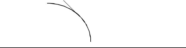
where n is the normal direction of the boundary. Note that the given values in the boundary conditions shown above can be non-zero values as well.
s
 n
n
boundary
© 1997-2002 Yijun Liu, University of Cincinnati |
125 |