


 ATtiny2313A/4313
19. Self-Programming
19.1Features
•Self-Programming Enables MCU to Erase, Write and Reprogram Application Memory
•Efficient Read-Modify-Write Support
•Lock Bits Allow Application Memory to Be Securely Closed for Further Access
19.2Overview
The device provides a self-programming mechanism for downloading and uploading program code by the MCU itself. Self-Programming can use any available data interface and associated protocol to read code and write (program) that code into program memory.
19.3Lock Bits
Program memory can be protected from internal or external access. See “Lock Bits” on page 178.
19.4Self-Programming the Flash
Program memory is updated in a page by page fashion. Before programming a page with the data stored in the temporary page buffer, the page must be erased. The temporary page buffer is filled one word at a time using SPM and the buffer can be filled either before the Page Erase command or between a Page Erase and a Page Write operation:
1.Either, fill the buffer before a Page Erase:
a.Fill temporary page buffer
b.Perform a Page Erase
c.Perform a Page Write
2.Or, fill the buffer after Page Erase:
a.Perform a Page Erase
b.Fill temporary page buffer
c.Perform a Page Write
If only a part of the page needs to be changed, the rest of the page must be stored (for example in the temporary page buffer) before the erase, and then be re-written.
The temporary page buffer can be accessed in a random sequence.
It is essential that the page address used in both the Page Erase and Page Write operation is addressing the same page.
The SPM instruction is disabled by default but it can be enabled by programming the SELFPRGEN fuse (to “0”).
19.4.1Addressing the Flash During Self-Programming
The Z-pointer is used to address the SPM commands.
Bit |
15 |
14 |
13 |
12 |
11 |
10 |
9 |
8 |
|
ZH (R31) |
Z15 |
Z14 |
Z13 |
Z12 |
Z11 |
Z10 |
Z9 |
Z8 |
|
|
|
|
|
|
|
|
|
|
|
ZL (R30) |
Z7 |
Z6 |
Z5 |
Z4 |
Z3 |
Z2 |
Z1 |
Z0 |
|
|
|
|
|
|
|
|
|
|
|
|
|
7 |
6 |
5 |
4 |
3 |
2 |
1 |
0 |
173
8246B–AVR–09/11
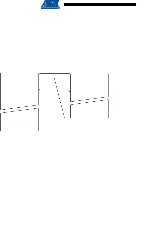
Since the Flash is organized in pages (see Table 21-1 on page 184), the Program Counter can be treated as having two different sections. One section, consisting of the least significant bits, is addressing the words within a page, while the most significant bits are addressing the pages. This is shown in Figure 19-1, below.
Figure 19-1. Addressing the Flash During SPM
BIT 15 |
|
|
|
ZPCMSB |
|
|
|
ZPAGEMSB 1 0 |
|
|||||||||
Z - REGISTER |
|
|
|
|
|
|
|
|
|
|
|
|
0 |
|
|
|
|
|
|
|
|
|
|
|
|
|
|
|
|
|
|
|
|
|
|
|
|
|
PROGRAM |
|
PCMSB |
|
|
|
PAGEMSB |
|
|
|
|
|||||||
|
|
|
PCPAGE |
PCWORD |
|
|
|
|
|
|||||||||
|
COUNTER |
|
|
|
|
|
||||||||||||
|
|
|
|
|
|
|
|
|
|
|
|
|
|
|||||
|
|
|
PAGE ADDRESS |
|
|
WORD ADDRESS |
|
|||||||||||
|
|
|
WITHIN THE FLASH |
|
|
WITHIN A PAGE |
|
|||||||||||
PROGRAM MEMORY |
|
|
|
|
|
|
|
|
|
PAGE |
PCWORD[PAGEMSB:0]: |
|||||||
|
|
|
|
|
|
|
|
|
|
|
|
|
|
|
|
|
|
|
|
PAGE |
|
|
|
|
|
|
|
|
|
|
|
|
INSTRUCTION WORD |
00 |
|||
|
|
|
|
|
|
|
|
|
|
|
|
|
|
|
||||
|
|
|
|
|
|
|
|
|
|
|
|
|
|
|
|
|
|
01 |
|
|
|
|
|
|
|
|
|
|
|
|
|
|
|
|
|
|
|
|
|
|
|
|
|
|
|
|
|
|
|
|
|
|
|
|
|
02 |
|
|
|
|
|
|
|
|
|
|
|
|
|
|
|
|
|
|
|
|
|
|
|
|
|
|
|
|
|
|
|
|
|
|
|
|
|
|
|
|
|
|
|
|
|
|
|
|
|
|
|
|
|
|
|
|
|
|
|
|
|
|
|
|
|
|
|
|
|
|
|
|
|
|
|
|
|
|
|
|
|
|
|
|
|
|
|
|
|
|
|
|
|
|
|
|
|
|
|
|
|
|
|
|
|
|
|
|
|
|
|
|
|
|
|
|
|
|
|
|
|
|
|
|
|
|
|
|
|
|
|
|
|
|
|
|
|
|
|
|
|
|
|
|
|
|
|
|
|
|
|
|
|
|
|
|
|
|
|
|
|
|
|
|
|
|
|
|
|
|
|
|
|
|
|
|
|
|
|
|
|
|
|
|
|
|
|
|
|
|
|
|
|
|
|
|
|
|
|
|
|
|
|
|
|
|
|
|
|
|
|
|
|
|
|
|
|
|
|
|
|
|
|
|
|
|
|
|
|
|
|
|
|
|
|
|
|
|
|
|
|
|
|
|
|
|
|
|
|
|
|
|
|
|
|
|
|
|
|
|
|
|
|
|
|
|
PAGEEND
Variables used in Figure 19-1 are explained in Table 19-1, below.
Table 19-1. |
Variables Used in Flash Addressing |
|
Variable |
|
Description |
|
|
|
PCPAGE |
|
Program Counter page address. Selects page of words and is used with Page |
|
Erase and Page Write operations. See Table 21-1 on page 184 |
|
|
|
|
|
|
|
PCMSB |
|
The most significant bit of the Program Counter. See Table 21-1 on page 184 |
|
|
|
ZPCMSB |
|
The bit in the Z register that is mapped to PCMSB. Because Z[0] is not used, |
|
ZPCMSB = PCMSB + 1. Z register bits above ZPCMSB are ignored |
|
|
|
|
|
|
|
|
|
Program Counter word address. Selects the word within a page. This is used |
PCWORD |
|
for filling the temporary buffer and must be zero during page write operations. |
|
|
See Table 21-1 on page 184 |
|
|
|
PAGEMSB |
|
The most significant bit used to address the word within one page |
|
|
|
ZPAGEMSB |
|
The bit in the Z register that is mapped to PAGEMSB. Because Z[0] is not used, |
|
ZPAGEMSB = PAGEMSB + 1 |
|
|
|
|
|
|
|
Note that the Page Erase and Page Write operations are addressed independently. Therefore it is of major importance that the software addresses the same page in both the Page Erase and Page Write operation.
174 ATtiny2313A/4313 
8246B–AVR–09/11

 ATtiny2313A/4313
Although the least significant bit of the Z-register (Z0) should be zero for SPM, it should be noted that the LPM instruction addresses the Flash byte-by-byte and uses Z0 as a byte select bit.
Once a programming operation is initiated, the address is latched and the Z-pointer can be used for other operations.
19.4.2Page Erase
To execute Page Erase:
•Set up the address in the Z-pointer
•Write “00000011” to SPMCSR
•Execute an SPM instruction within four clock cycles after writing SPMCSR
The data in R1 and R0 is ignored. The page address must be written to PCPAGE in the Z-regis- ter. Other bits in the Z-pointer are ignored during this operation.
If an interrupt occurs during the timed sequence above the four cycle access cannot be guaranteed. In order to ensure atomic operation interrupts should be disabled before writing to SPMCSR.
The CPU is halted during the Page Erase operation.
19.4.3Page Load
To write an instruction word:
•Set up the address in the Z-pointer
•Set up the data in R1:R0
•Write “00000001” to SPMCSR
•Execute an SPM instruction within four clock cycles after writing SPMCSR
The content of PCWORD in the Z-register is used to address the data in the temporary buffer. The temporary buffer will auto-erase after a Page Write operation, or by writing the RWWSRE bit in SPMCSR. It is also erased after a system reset.
Note that it is not possible to write more than one time to each address without erasing the temporary buffer.
If the EEPROM is written in the middle of an SPM Page Load operation, all data loaded will be lost.
19.4.4Page Write
To execute Page Write:
•Set up the address in the Z-pointer
•Write “00000101” to SPMCSR
•Execute an SPM instruction within four clock cycles after writing SPMCSR
The data in R1 and R0 is ignored. The page address must be written to PCPAGE. Other bits in the Z-pointer must be written to zero during this operation.
The CPU is halted during the Page Write operation.
175
8246B–AVR–09/11