

files / 421_гис-2 / arcview 3.2a / avdocs / shapefile
.pdfESRI Shapefile Technical Description
J-7855
PolyLineZ A PolyLineZ consists of one or more parts. A part is a connected sequence of two or more points. Parts may or may not be connected to one another. Parts may or may not intersect one another.
PolyLineZ |
|
|
{ |
|
|
Double[4] |
Box |
// Bounding Box |
Integer |
NumParts |
// Number of Parts |
Integer |
NumPoints |
// Total Number of Points |
Integer[NumParts] |
Parts |
// Index to First Point in Part |
Point[NumPoints] |
Points |
// Points for All Parts |
Double[2] |
Z Range |
// Bounding Z Range |
Double[NumPoints] |
Z Array |
// Z Values for All Points |
Double[2] |
M Range |
// Bounding Measure Range |
Double[NumPoints] |
M Array |
// Measures |
} |
|
|
The fields for a PolyLineZ are described in detail below:
Box |
The Bounding Box for the PolyLineZ stored in the order Xmin, Ymin, |
|
Xmax, Ymax. |
NumParts |
The number of parts in the PolyLineZ. |
NumPoints |
The total number of points for all parts. |
Parts |
An array of length NumParts. Stores, for each part, the index of its first |
|
point in the points array. Array indexes are with respect to 0. |
Points |
An array of length NumPoints. The points for each part in the PolyLineZ |
|
are stored end to end. The points for Part 2 follow the points for Part 1, and |
|
so on. The parts array holds the array index of the starting point for each |
|
part. There is no delimiter in the points array between parts. |
Z Range |
The minimum and maximum Z values for the PolyLineZ stored in the order |
|
Zmin, Zmax. |
Z Array |
An array of length NumPoints. The Z values for each part in the PolyLineZ |
|
are stored end to end. The Z values for Part 2 follow the Z values for Part 1, |
|
and so on. The parts array holds the array index of the starting point for |
|
each part. There is no delimiter in the Z array between parts. |
M Range |
The minimum and maximum measures for the PolyLineZ stored in the order |
|
Mmin, Mmax. |
M Array |
An array of length NumPoints. The measures for each part in the PolyLineZ |
|
are stored end to end. The measures for Part 2 follow the measures for Part |
ESRI White Paper |
17 |
ESRI Shapefile Technical Description
J-7855
1, and so on. The parts array holds the array index of the starting measure for each part. There is no delimiter in the measure array between parts.
Table 14
PolyLineZ Record Contents
|
|
|
|
|
Byte |
Position |
Field |
Value |
Type |
Number |
Order |
Byte 0 |
Shape Type |
13 |
Integer |
1 |
Little |
Byte 4 |
Box |
Box |
Double |
4 |
Little |
Byte 36 |
NumParts |
NumParts |
Integer |
1 |
Little |
Byte 40 |
NumPoints |
NumPoints |
Integer |
1 |
Little |
Byte 44 |
Parts |
Parts |
Integer |
NumParts |
Little |
Byte X |
Points |
Points |
Point |
NumPoints |
Little |
Byte Y |
Zmin |
Zmin |
Double |
1 |
Little |
Byte Y + 8 |
Zmax |
Zmax |
Double |
1 |
Little |
Byte Y + 16 |
Zarray |
Zarray |
Double |
NumPoints |
Little |
Byte Z* |
Mmin |
Mmin |
Double |
1 |
Little |
Byte Z+8* |
Mmax |
Mmax |
Double |
1 |
Little |
Byte Z+16* |
Marray |
Marray |
Double |
NumPoints |
Little |
Note: X = 44 + (4 * NumParts), Y = X + (16 * NumPoints), Z = Y + 16 + (8 * NumPoints) * optional
PolygonZ A PolygonZ consists of a number of rings. A ring is a closed, non-self-intersecting loop. A PolygonZ may contain multiple outer rings. The rings of a PolygonZ are referred to as its parts.
The PolygonZ structure is identical to the PolyLineZ structure, as follows:
PolygonZ |
|
|
{ |
|
|
Double[4] |
Box |
// Bounding Box |
Integer |
NumParts |
// Number of Parts |
Integer |
NumPoints |
// Total Number of Points |
Integer[NumParts] |
Parts |
// Index to First Point in Part |
Point[NumPoints] |
Points |
// Points for All Parts |
Double[2] |
Z Range |
// Bounding Z Range |
Double[NumPoints] |
Z Array |
// Z Values for All Points |
Double[2] |
M Range |
// Bounding Measure Range |
Double[NumPoints] |
M Array |
// Measures |
} |
|
|
March 1998 |
18 |
ESRI Shapefile Technical Description
J-7855
The fields for a PolygonZ are
Box |
The Bounding Box for the PolygonZ stored in the order Xmin, Ymin, |
|
Xmax, Ymax. |
NumParts |
The number of rings in the PolygonZ. |
NumPoints |
The total number of points for all rings. |
Parts |
An array of length NumParts. Stores, for each ring, the index of its first |
|
point in the points array. Array indexes are with respect to 0. |
Points |
An array of length NumPoints. The points for each ring in the PolygonZ are |
|
stored end to end. The points for Ring 2 follow the points for Ring 1, and so |
|
on. The parts array holds the array index of the starting point for each ring. |
|
There is no delimiter in the points array between rings. |
Z Range |
The minimum and maximum Z values for the arc stored in the order Zmin, |
|
Zmax. |
Z Array |
An array of length NumPoints. The Z values for each ring in the PolygonZ |
|
are stored end to end. The Z values for Ring 2 follow the Z values for |
|
Ring 1, and so on. The parts array holds the array index of the starting Z |
|
value for each ring. There is no delimiter in the Z value array between |
|
rings. |
M Range |
The minimum and maximum measures for the PolygonZ stored in the order |
|
Mmin, Mmax. |
M Array |
An array of length NumPoints. The measures for each ring in the PolygonZ |
|
are stored end to end. The measures for Ring 2 follow the measures for |
|
Ring 1, and so on. The parts array holds the array index of the starting |
|
measure for each ring. There is no delimiter in the measure array between |
|
rings. |
The following are important notes about PolygonZ shapes.
The rings are closed (the first and last vertex of a ring MUST be the same).
The order of rings in the points array is not significant.
ESRI White Paper |
19 |
ESRI Shapefile Technical Description
J-7855
Table 15
PolygonZ Record Contents
|
|
|
|
|
Byte |
Position |
Field |
Value |
Type |
Number |
Order |
Byte 0 |
Shape Type |
15 |
Integer |
1 |
Little |
Byte 4 |
Box |
Box |
Double |
4 |
Little |
Byte 36 |
NumParts |
NumParts |
Integer |
1 |
Little |
Byte 40 |
NumPoints |
NumPoints |
Integer |
1 |
Little |
Byte 44 |
Parts |
Parts |
Integer |
NumParts |
Little |
Byte X |
Points |
Points |
Point |
NumPoints |
Little |
Byte Y |
Zmin |
Zmin |
Double |
1 |
Little |
Byte Y+8 |
Zmax |
Zmax |
Double |
1 |
Little |
Byte Y+16 |
Zarray |
Zarray |
Double |
NumPoints |
Little |
Byte Z* |
Mmin |
Mmin |
Double |
1 |
Little |
Byte Z+8* |
Mmax |
Mmax |
Double |
1 |
Little |
Byte Z+16* |
Marray |
Marray |
Double |
NumPoints |
Little |
Note: X = 44 + (4 * NumParts), Y = X + (16 * NumPoints), Z = Y + 16 + (8 * NumPoints)
* optional
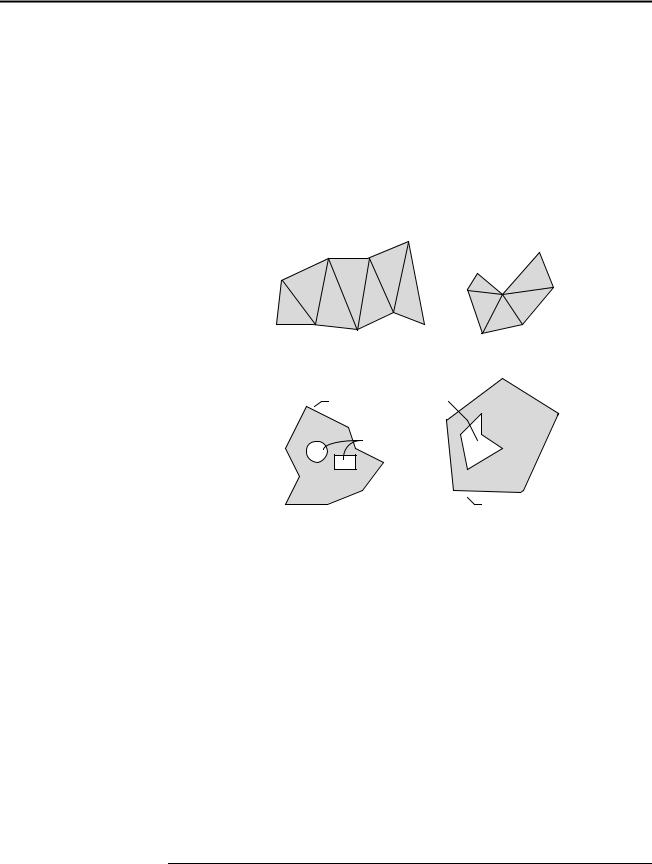
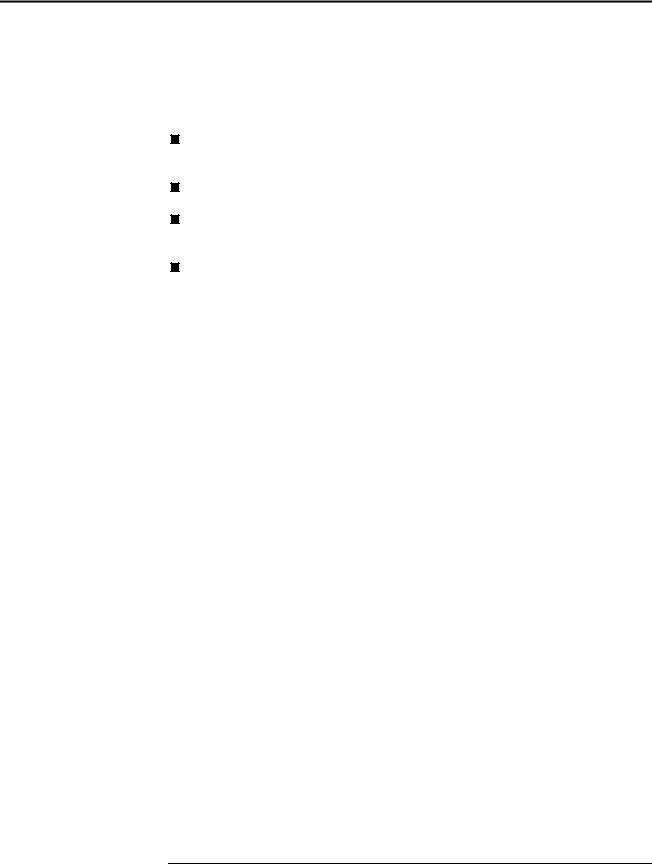
MultiPatch A MultiPatch consists of a number of surface patches. Each surface patch describes a surface. The surface patches of a MultiPatch are referred to as its parts, and the type of part controls how the order of vertices of an MultiPatch part is interpreted. The parts of a MultiPatch can be of the following types:
Triangle Strip A linked strip of triangles, where every vertex (after the first two) completes a new triangle. A new triangle is always formed by connecting the new vertex with its two immediate predecessors.
Triangle Fan A linked fan of triangles, where every vertex (after the first two) completes a new triangle. A new triangle is always formed by connecting the new vertex with its immediate predecessor and the first vertex of the part.
Outer Ring The outer ring of a polygon.
Inner Ring A hole of a polygon.
First Ring The first ring of a polygon of an unspecified type.
|
Ring |
A ring of a polygon of an unspecified type. |
|
A single Triangle Strip, or Triangle Fan, represents a single surface patch. See Figure 3 for examples of those part types.
March 1998 |
20 |
ESRI Shapefile Technical Description
J-7855
A sequence of parts that are rings can describe a polygonal surface patch with holes. The sequence typically consists of an Outer Ring, representing the outer boundary of the patch, followed by a number of Inner Rings representing holes. When the individual types of rings in a collection of rings representing a polygonal patch with holes are unknown, the sequence must start with First Ring, followed by a number of Rings. A sequence of Rings not preceded by an First Ring is treated as a sequence of Outer Rings without holes.
Figure 3
MultiPatch Part Examples
|
|
V8 |
V2 |
|
|
V4 |
V6 |
|
|
|
|
|
||
V2 |
|
|
V7 |
|
|
|
V1 |
V3 |
|
|
|
|
||
|
|
|
V6 |
|
|
|
V7 |
V4 |
|
V1 |
V3 |
V9 |
|
|
V5 |
V5 |
|
||
|
|
|
|
|
|
Triangle Strip |
Triangle Fan |
|
|
First
Outer Ring
Ring
Inner Rings
Ring
This figure shows examples of all types of MultiPatch parts.
The values used for encoding part type are as follows:
Value |
Part Type |
0 |
Triangle Strip |
1 |
Triangle Fan |
2 |
Outer Ring |
3 |
Inner Ring |
4 |
First Ring |
5 |
Ring |
ESRI White Paper |
21 |

ESRI Shapefile Technical Description
J-7855
MultiPatch |
|
|
{ |
|
|
Double[4] |
Box |
// Bounding Box |
Integer |
NumParts |
// Number of Parts |
Integer |
NumPoints |
// Total Number of Points |
Integer[NumParts] |
Parts |
// Index to First Point in Part |
Integer[NumParts] |
PartTypes |
// Part Type |
Point[NumPoints] |
Points |
// Points for All Parts |
Double[2] |
Z Range |
// Bounding Z Range |
Double[NumPoints] |
Z Array |
// Z Values for All Points |
Double[2] |
M Range |
// Bounding Measure Range |
Double[NumPoints] |
M Array |
// Measures |
}
The fields for a MultiPatch are
Box |
The Bounding Box for the MultiPatch stored in the order Xmin, Ymin, |
|
Xmax, Ymax. |
NumParts |
The number of parts in the MultiPatch. |
NumPoints |
The total number of points for all parts. |
Parts |
An array of length NumParts. Stores, for each part, the index of its first |
|
point in the points array. Array indexes are with respect to 0. |
PartTypes |
An array of length NumParts. Stores for each part its type. |
Points |
An array of length NumPoints. The points for each part in the MultiPatch |
|
are stored end to end. The points for Part 2 follow the points for Part 1, and |
|
so on. The parts array holds the array index of the starting point for each |
|
part. There is no delimiter in the points array between parts. |
Z Range |
The minimum and maximum Z values for the arc stored in the order Zmin, |
|
Zmax. |
Z Array |
An array of length NumPoints. The Z values for each part in the MultiPatch |
|
are stored end to end. The Z values for Part 2 follow the Z values for Part 1, |
|
and so on. The parts array holds the array index of the starting Z value for |
|
each part. There is no delimiter in the Z value array between parts. |
M Range |
The minimum and maximum measures for the MultiPatch stored in the |
|
order Mmin, Mmax. |
M Array |
An array of length NumPoints. The measures for each part in the |
|
MultiPatch are stored end to end. The measures for Part 2 follow the |
|
measures for Part 1, and so on. The parts array holds the array index of the |
March 1998 |
22 |
ESRI Shapefile Technical Description
J-7855
Organization of the
Index File
starting measure for each part. There is no delimiter in the measure array between parts.
The following are important notes about MultiPatch shapes.
If a part is a ring, it must be closed (the first and last vertex of a ring MUST be the same).
The order of parts that are rings in the points array is significant: Inner Rings must follow their Outer Ring; a sequence of Rings representing a single surface patch must start with a ring of the type First Ring.
Parts can share common boundaries, but parts must not intersect and penetrate each other.
Table 16
MultiPatch Record Contents
|
|
|
|
|
Byte |
Position |
Field |
Value |
Type |
Number |
Order |
Byte 0 |
Shape Type |
31 |
Integer |
1 |
Little |
Byte 4 |
Box |
Box |
Double |
4 |
Little |
Byte 36 |
NumParts |
NumParts |
Integer |
1 |
Little |
Byte 40 |
NumPoints |
NumPoints |
Integer |
1 |
Little |
Byte 44 |
Parts |
Parts |
Integer |
NumParts |
Little |
Byte W |
PartTypes |
PartTypes |
Integer |
NumParts |
Little |
Byte X |
Points |
Points |
Point |
NumPoints |
Little |
Byte Y |
Zmin |
Zmin |
Double |
1 |
Little |
Byte Y+8 |
Zmax |
Zmax |
Double |
1 |
Little |
Byte Y+16 |
Zarray |
Zarray |
Double |
NumPoints |
Little |
Byte Z* |
Mmin |
Mmin |
Double |
1 |
Little |
Byte Z+8* |
Mmax |
Mmax |
Double |
1 |
Little |
Byte Z+16* |
Marray |
Marray |
Double |
NumPoints |
Little |
Note: W = 44 + (4 * NumParts), X = W + (4 * NumParts), Y = X + (16 * NumPoints), Z = Y + 16 + (8 * NumPoints)
* optional
The index file (.shx) contains a 100-byte header followed by 8-byte, fixed-length records. Figure 4 illustrates the index file organization.
ESRI White Paper |
23 |
ESRI Shapefile Technical Description
The Index File Header
Index Records
J-7855
Figure 4
Organization of the Index File
File Header
Record
Record
Record
Record
. . .
. . .
Record
The index file header is identical in organization to the main file header described above. The file length stored in the index file header is the total length of the index file in 16-bit words (the fifty 16-bit words of the header plus 4 times the number of records).
The I’th record in the index file stores the offset and content length for the I’th record in the main file. Table 17 shows the fields in the file header with their byte position, value, type, and byte order. In the table, position is with respect to the start of the index file record.
Table 17
Description of Index Records
|
|
|
|
Byte |
|
Position |
Field |
Value |
Type |
Order |
|
Byte 0 |
Offset |
Offset |
Integer |
Big |
|
Byte 4 |
Content Length |
Content Length |
Integer |
Big |
The offset of a record in the main file is the number of 16-bit words from the start of the main file to the first byte of the record header for the record. Thus, the offset for the first record in the main file is 50, given the 100-byte header.
The content length stored in the index record is the same as the value stored in the main file record header.
March 1998 |
24 |
ESRI Shapefile Technical Description
J-7855
Organization of
the dBASE File
The dBASE file (.dbf) contains any desired feature attributes or attribute keys to which other tables can be joined. Its format is a standard DBF file used by many table-based applications in Windows™ and DOS. Any set of fields can be present in the table. There are three requirements, as follows:
The file name must have the same prefix as the shape and index file. Its suffix must be .dbf. (See the example on page 2, in Naming Conventions.)
The table must contain one record per shape feature.
The record order must be the same as the order of shape features in the main (*.shp) file.
The year value in the dBASE header must be the year since 1900.
For more information on the dBASE file format, visit the INPRISE Corp. Web site at www.inprise.com.
ESRI White Paper |
25 |

ESRI Shapefile Technical Description
J-7855
Glossary
ARC/INFO
ArcCAD
ARC Macro
Language (AML)
ArcView GIS
Avenue
big endian byte order
Bounding Box
BusinessMAP
Key terms are defined below that will help you understand the concepts discussed in this document.
ARC/INFO software is designed for users who require a complete set of tools for processing and manipulating spatial data including digitizing, editing, coordinate management, network analysis, surface modeling, and grid cell based modeling.
ARC/INFO operates on a large variety of workstations and minicomputers. Using open standards and client/server architecture, ARC/INFO can act as a GIS server for ArcView GIS clients.
ArcCAD software brings the functionality of ARC/INFO GIS software to the AutoCAD environment, providing comprehensive data management, spatial analysis, and display tools.
ARC Macro Language is a high-level, algorithmic language that provides full programming capabilities and a set of tools to tailor the user interface of your application.
ArcView GIS software is a powerful, easy-to-use desktop GIS that gives you the power to visualize, explore, query, and analyze data spatially. ArcView GIS operates in Windows desktop environments as well as a large variety of workstations.
Avenue software is an object-oriented programming language and development environment created for use with ArcView GIS software. Avenue can be used to extend ArcView GIS software’s basic capabilities and customize ArcView GIS for specific applications.
Left-to-right byte ordering of an integer word. This byte-ordering method is used on many UNIX systems including Sun, Hewlett–Packard ® , IBM® , and Data General AViiON® .
A Bounding Box is a rectangle surrounding each shape (e.g., PolyLine) that is just large enough to contain the entire shape. It is defined as Xmin,Ymin, Xmax,Ymax.
BusinessMAP database mapping software for Windows allows you to create custom maps and represent information in twoor three-dimensional charts. BusinessMAP reads ESRI shapefiles and works with the leading contact managers, databases, and spreadsheets.
March 1998 |
26 |