

4afe
.pdf92 |
ENGINEÐ4A±FE ENGINE |
|
|
4A±FE ENGINE
DESCRIPTION
The 4A±FE engine is the dependable, lightweight and compact DOHC engine that is currently carried in the Corolla All±Trac/4WD station wagons ('89 model AE95 series). Although the basic construction and operation are identical to the engine used in the '89 model AE95 series, the crankshaft pulley, intake manifold, throttle body, engine mount, etc., were modified to ensure a better match with the new Celica.
|
|
ENGINEÐ4A±FE ENGINE |
93 |
|
|
|
|
|
|
|
|
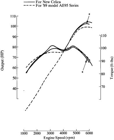
ENGINE SPECIFICATIONS AND PERFORMANCE CURVE |
|
|
|||
|
|
|
|
|
|
|
|
Engine |
4A±FE |
4A±FE |
|
|
|
|
|
||
|
Item |
|
(for new Celica) |
(for '89 model AE95 series) |
|
|
|
|
|
|
|
|
No. of Cyls. & Arrangement |
|
4±cylinder, In±line |
← |
|
|
|
|
|
|
|
|
Valve Mechanism |
|
4 Valves, DOHC, |
← |
|
|
|
Belt & Gear Drive |
|
||
|
|
|
|
|
|
|
|
|
|
|
|
|
Combustion Chamber |
|
Pentroof Type |
← |
|
|
|
|
|
|
|
|
Manifolds |
|
Cross±flow |
← |
|
|
|
|
|
|
|
|
Displacement |
cu. in. (cc) |
96.8 (1587) |
← |
|
|
|
|
|
|
|
|
Bore x Stroke |
in. (mm) |
3.19 x 3.03 (81 x 77) |
← |
|
|
|
|
|
|
|
|
Compression Ratio |
|
9.5 : 1 |
← |
|
|
|
|
|
|
|
|
Max. Output |
(SAE±NET) |
103 HP @ 6000 rpm |
100 HP @ 5600 rpm |
|
|
102 HP @ 5800 rpm* |
|
|||
|
|
|
|
|
|
|
|
|
|
|
|
|
Max. Torque |
(SAE±NET) |
102 HP @ 3200 rpm |
101 ft.lbs @ 4400 rpm |
|
|
101 ft.lbs @ 4800 rpm* |
|
|||
|
|
|
|
|
|
|
Fuel Octane Number |
(RON) |
91 |
← |
|
|
|
|
|
|
|
|
Oil Grade |
|
API SG |
API SF or SG |
|
|
|
|
|
|
|
*: Applicable only to California specification vehicles.
94 |
ENGINEÐ4A±FE ENGINE |
|
|
ENGINE
1.Crankshaft Pulley
The crankshaft pulley has a torsional damper that reduces torsional vibration of the crankshaft. In addition, it has a longitudinal damper to reduce longitudinal vibration of the crankshaft. These dampers jointly minimize vibration and noise.
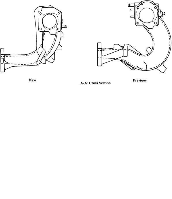
2. Intake Manifold
The intake manifold is integrated with the intake air chamber to reduce the overall weight. The intake pipe length and the port diameter were optimized to further increase torque in low to medium speed ranges.
ENGINEÐ4A±FE ENGINE |
95 |
|
|
3. Throttle Body
The construction of the throttle body has been changed from the type with incorporated air valve in the '89 model AE95 series to the type with separate air valve. The basic operation is unchanged.
ENGINE MOUNTING
1.Cylindrical Liquid±filled Compound Mount
A newly±developed cylindrical liquid±filled compound mount is used in both the left and right mounts. See page 75 under 5S±FE engine for detail.
96 |
ENGINEÐ4A±FE ENGINE |
|
|
ENGINE CONTROL SYSTEM
1.General
The engine control system of the 4A±FE engine for the new Celica is basically the same functionally as the 4A±FE engine carried in the Corolla All±Trac/4WD station wagons ('89 model AE95 series), but it incorporates some modifications. The following table compares the engine control systems between the new Celica and the '89 model AE95 series:
Engine |
|
|
New 4A±FE |
|
|
Previous 4A±FE |
|
|
|
|
|
|
|||
System |
|
(for new Celica) |
|
|
(for '89 model AE95 series) |
||
|
|
|
|||||
|
A D±type EFI system is used which |
|
|||||
EFI |
indirectly detects intake air volume by the |
← |
|||||
(Electronic Fuel |
manifold pressure sensor signal. |
|
|||||
Injection) |
The |
fuel |
injection |
system |
is |
|
|
|
simultaneously an all injection system. |
|
|
||||
|
|
|
|
||||
ESA |
Ignition timing is determined by the ECU |
|
← |
||||
(Electronic Spark |
(Electronic Control Unit) based on signals |
|
|||||
Advance) |
from various sensors. |
|
|
|
|||
|
|
|
|
|
|
|
|
ISC |
ACV regulates air volume by passing |
|
← |
||||
(Idle Speed |
|
||||||
throttle valve and controls idling speed. |
|
||||||
Control) |
|
|
|||||
|
|
|
|
|
|
||
|
|
|
|||||
EGR Cut±Off |
The EGR is cut off under light engine loads |
|
|||||
or low temperature conditions to maintain |
|
N.A. |
|||||
Control |
|
||||||
drivability. |
|
|
|
|
|||
|
|
|
|
|
|||
|
|
|
|
||||
Fuel Pump |
Fuel pump operation is controlled by |
|
← |
||||
Control |
signals from ECU. |
|
|
||||
|
|
|
|||||
|
|
|
|
||||
|
By controlling the air conditioner |
|
|
||||
Air Conditioner |
compressor in accordance with the throttle |
N.A. |
|||||
Cut±Off Control |
valve opening angle and the vehicle speed, |
||||||
|
|||||||
|
drivability is maintained. |
|
|
|
|||
|
|
|
|
||||
OD Gear Shift |
Prohibits OD gear shift depending on |
|
|
||||
engine condition to main good drivability |
|
N.A. |
|||||
Lockout Control* |
|
||||||
and acceleration performance. |
|
|
|
||||
|
|
|
|
||||
|
|
|
|||||
|
When a malfunction occurs, the ECU |
|
|||||
|
diagnoses and memorizes the failed |
|
|||||
Diagnosis |
section. |
|
|
|
|
|
|
|
14 diagnostic items are monitored by the |
|
|||||
|
ECU. |
|
|
|
|
|
|
|
|
|
|||||
|
When a malfunction occurs, the ECU stops |
← |
|||||
Fail±Safe |
or controls the engine according to the data |
||||||
|
already stored in memory. |
|
|
|
|||
|
|
|
|
|
|
|
|
*: Applicable only to automatic transaxle models.
ENGINEÐ4A±FE ENGINE |
97 |
|
|
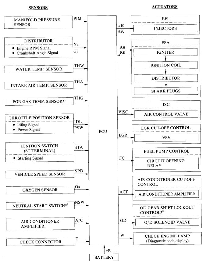
2. Construction
The engine control system can be divided into three groups; the sensors, ECU and actuators.
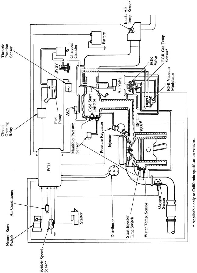
*1: Applicable only to California specification vehicles. *2: Applicable only to automatic transaxle models.
98 |
ENGINEÐ4A±FE ENGINE |
|
|
3. Engine Control System Diagram
ENGINEÐ4A±FE ENGINE |
99 |
|
|
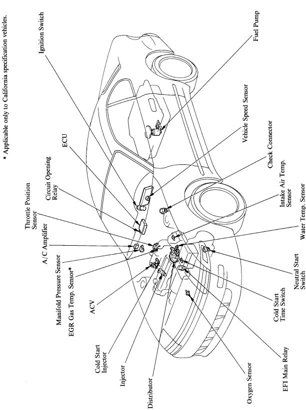
4. Arrangement of Engine Control System Components

100 |
ENGINEÐ4A±FE ENGINE |
|
|
5. EGR Cut±Off Control
This system actuates the VSV to replace intake manifold vacuum acting on the EGR vacuum modulator with atmospheric air and thus cuts the EGR from the system.
Operation
To maintain vehicle drivability and durability of the EGR components, the ECU actuates off the VSV and cuts the EGR when the coolant temperature is below 127°F (53°C) and the engine load is above a predetermined level.
6. Air Conditioner Cut±Off Control
The ECU sends a signal to the air conditioner amplifier to disengage the air conditioner compressor magnet clutch and cuts off the air conditioning operation according to the engine speed, intake manifold pressure, vehicle speed and throttle valve opening angle.
Operation
The air conditioner is turned off during quick acceleration from a low engine speed, depending on the vehicle speed, throttle valve position and the intake manifold pressure. This helps maintain good acceleration performance.
The air conditioner is also turned off when the engine is idling at a speed below 500 rpm. This prevents the engine from stalling.
RELEVANT SIGNALS
Throttle position (IDL, PSW)
Vehicle speed (SPD)
Intake manifold pressure (PIM)
Engine speed (Ne)
Neutral start switch* (NSW)
*: Applicable only to automatic transaxle models.
ENGINEÐ4A±FE ENGINE |
101 |
|
|
7. OD Gear Shift Lockout Control (for A240L Automatic Transaxle Models)
The ECU turns the OD solenoid valve of the automatic transaxle on depending on the coolant temperature and the acceleration condition of the vehicle. This prohibits shifting to the OD gear to maintain good drivability and acceleration performance.
Operation
This control is used when the coolant temperature is below 122°F (50°C) to maintain good drivability. The same control used to be done by the water temperature switch in the previous engine, but is now done by the engine ECU in the new 4A±FE engine. Shifting to the OD gear is also prohibited during quick acceleration in low to medium speed ranges to maintain good acceleration performance.
RELEVANT SIGNALS
Coolant temperature (THW)
Vehicle speed (SPD)
Engine speed (Ne)
Throttle position (PSW)
Intake manifold pressure (PIM)