

- •1.1 System Description
- •1.2 Line Replaceable Units
- •1.3 PFD/MFD Controls
- •1.4 Secure Digital Cards
- •1.5 System Power-up
- •1.6 Display Backlighting
- •1.7 System Operation
- •Normal Mode
- •Reversionary Mode
- •AHRS Operation
- •2.1 Introduction
- •2.2 Backlighting
- •2.3 Softkey Function
- •2.4 Flight Instruments
- •Airspeed Indicator
- •Attitude Indicator
- •Altimeter
- •Vertical Speed Indicator
- •Horizontal Situation Indicator
- •Communication Frequency Window
- •Navigation Frequency Window
- •Navigation Status Bar
- •Transponder Status Bar
- •2.6 Supplemental Flight Data
- •Outside Air Temperature Box
- •System Time Box
- •Traffic Annunciation
- •Terrain Proximity
- •Terrain Awareness and Warning System (TAWS) (Optional)
- •Inset Map
- •Working with Menus
- •Auxiliary Window Keys
- •Auxiliary Windows
- •2.7 Reversionary Mode
- •2.8 Alerts and Annunciations
- •Alerts Window
- •Annunciation Window
- •Softkey Annunciations
- •3.1 Overview
- •Windows and Fields
- •Radio Selection
- •Controls
- •Tuning Box
- •Switching Between Radios
- •Manually Tuning a Frequency
- •Radio Indicators
- •Volume
- •Frequency Transfer Arrow
- •3.2 COM Operation
- •Frequency Spacing
- •Automatic Squelch
- •Selecting a COM Radio
- •Emergency Frequency (121.500 MHz)
- •Quick-Tuning and Activating 121.500 MHz
- •Stuck Microphone
- •3.3 NAV Operation
- •Frequency Range
- •Morse Code Identifier
- •NAV Radio Selection for Navigation
- •ADF/DME Tuning
- •DME Tuning
- •3.4 Frequency Auto-tuning
- •Auto-tuning on the PFD
- •Auto-tuning on the MFD
- •Auto-Tuning on Approach Activation (NAV Frequencies)
- •4.1 Transponder Description
- •Transponder Softkeys
- •Transponder Status Bar
- •Mode S Features
- •Traffic Information Service (TIS)
- •4.2 Operation
- •Mode Selection
- •Code Selection
- •IDENT Function
- •5.1 Audio Panel Description
- •Transceivers
- •Mono/Stereo Headsets
- •Unmuted/Unswitched Inputs
- •Front Panel Controls
- •5.2 Operation
- •Power-up and Fail-safe Operation
- •Key Annunciators
- •Lighting
- •Transceiver Keys
- •Optional COM Muting
- •Split COM Function
- •PA Function
- •Speaker
- •Marker Beacon Receiver
- •Marker Beacon Volume Adjustment
- •Navigation Radios
- •Intercom System (ICS) Isolation
- •Intercom Volume and Squelch
- •Entertainment Inputs
- •GDL 69/69A XM Radio System
- •Master Avionics Squelch (MASQ)
- •Digital Clearance Recorder with Playback Capability
- •Reversionary Mode
- •6.1 Introduction
- •EIS Pages
- •EIS Indicators
- •EiS Page Reversion
- •6.2 Engine Page
- •6.3 Lean Page
- •6.4 System Page
- •7.1 Introduction
- •Description
- •Reversionary Mode
- •Optional Equipment
- •MFD Power-up
- •MFD Backlighting
- •MFD Softkeys
- •Electronic Checklists (optional)
- •MFD Page Groups
- •Working With Menus
- •7.2 Navigation Map Page
- •Navigation Map Page Operations
- •7.3 Traffic Map Page
- •TIS Symbology
- •Traffic Map Page Operations
- •7.4 Terrain Proximity Page
- •Terrain Proximity Page Operations
- •Displaying Obstacle Data
- •Navigation Map Display Conditions
- •Displaying Terrain on the TAWS Page
- •7.6 Direct-to Navigation
- •Direct-to Navigation Operations
- •7.7 Flight Plans
- •Active Flight Plan Page
- •Active Flight Plan Page Options
- •Flight Plan Catalog Page
- •Flight Plan Catalog Page Operations
- •Vertical Navigation (VNAV) Page
- •7.8 Procedures
- •Arrivals and Departures
- •Approaches
- •G1000 Navigational Guidance for Approaches
- •Selecting Approaches
- •7.9 Waypoint Page Group
- •AIRPORT Information Page (INFO)
- •Airport Frequency Information Field
- •AIRPORT Information Page Options
- •Departure Information Page (DP)
- •Arrival Information Page (STAR)
- •Approach Information Page
- •Intersection Information Page
- •NDB Information Page
- •VOR Information Page
- •User Waypoint Information Page
- •Creating User Waypoints
- •Modifying User Waypoints
- •User Waypoint Information Page Options
- •7.10 Auxiliary Page Group
- •Trip Planning Page
- •GPS Status Page
- •System Setup Page
- •System Status Page
- •7.11 Nearest Page Group
- •Navigating to a Nearest Waypoint
- •Nearest Intersections Page
- •Nearest NDB Page
- •Nearest VOR Page
- •Nearest User Waypoint Page
- •Nearest Frequencies Page
- •Nearest Airspaces Page
- •8.1 Introduction
- •8.2 WX-500 Stormscope
- •Displaying Stormscope Lightning Data on the Navigation Map Page
- •Stormscope Page
- •8.3 Traffic Advisory System
- •Displaying and Configuring TAS Traffic on the Navigation Map Page
- •Traffic Map Page
- •Failure Response
- •Description of Traffic Advisory Criteria
- •User-Initiated Test
- •TAS Voice Announcements
- •Switching Between Standby and Various Operating Modes
- •Altitude Display Mode
- •Traffic Map Page Display Range
- •8.4 XM Weather and XM Radio
- •Introduction
- •XM Weather
- •Weather Product Symbols
- •XM Digital Audio Entertainment
- •XM Radio Page
- •9.1 Introduction
- •9.2 Alert Level Definitions
- •9.4 CO Guardian Messages
- •9.6 G1000 System Annunciations
- •Appendices
- •Aviation Database
- •Terrain and Obstacle Databases
- •Introduction
- •TIS vs. TCAS
- •TIS Limitations
- •Airport
- •NAVAIDS
- •Basemap
- •Traffic
- •Lightning Strike
- •Impact Points (TAWS Only)
- •Miscellaneous
- •Line Symbols
- •Obstacle database
- •Terrain Color Chart
- •GMA 1347 Audio Panel
- •GIA 63 Integrated Avionics Units
- •GDC 74A Air Data Computer
- •GTX 33 Mode S Transponder
- •GEA 71 Engine/Airframe Unit
- •GDL 69/69A Weather Data Link
- •GRS 77 AHRS
- •Index
7.10 AUXILIARY PAGE GROUP
The Auxiliary Page Group (AUX) provides detailed trip planning information, satellite status, RAIM prediction, system settings, LRU status and database information.
The AUX Group page names are as follows:
•Trip Planning
•Utility
•GPS Status
•System Setup
•System Status
MULTI FUNCTION DISPLAY
To quickly select an Aux page:
1.From any page, press and hold the CLR key to select the Navigation Map Page.
2.Turn the large FMS knob to select the ‘AUX’ page group.
3.Turn the small FMS knob to select the desired AUX Page.
TRIP PLANNING PAGE
The Trip Planning Page calculates trip statistics, fuel statistics, and other statistics for a specified Direct-to, point-to-point, or flight plan based on automatic or manual input of data.
Figure 7-73 Trip Planning Page
190-00498-00 Rev.A |
Garmin G1000 Pilot’s Guide for Cessna Nav III |
7-105 |
MULTI FUNCTION DISPLAY
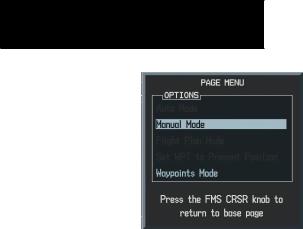
Figure 7-74 Trip Planning Page Menu
Trip Planning
Trip planning allows you to view desired track (DTK), distance (DIS), estimated time enroute (ETE), estimated time of arrival (ETA), and enroute safe altitude (ESA) for a Direct-to, point-to-point between two specified waypoints,orforanyprogrammedflightplan.Thisoption also displays the sunrise/sunset times for your destination waypoint (for the selected departure date).
To perform trip planning operations:
1.Select the AUX-TRIP PLANNING page.
2.The current page mode is displayed at the top of the page: ‘AUTOMATIC’ or ‘MANUAL’. To change the page mode, press the AUTO or MANUAL softkey.
3.For Direct-to planning, press the WPTS softkey and verify that the from waypoint field indicates P.POS (present position). If necessary, go to the Page Menu and select ‘Set WPT to Present Position’ to display P.POS. Press the ENT key and the flashing cursor moves to the ‘to’ waypoint field. Turn the small and large FMS knobs to enter the identifier of the ‘to’ waypoint and press the ENT key to accept the waypoint. OR,
4.For point-to-point planning, turn the small and large FMS knobs to enter the identifier of the from waypoint. Once the waypoints identifier is entered, press the ENT key to accept the waypoint. The flashing cursor moves to the ‘to’ waypoint. Again, turn the small and large FMS knobs to enter the identifier of the ‘to’ waypoint and press the ENT key to accept the waypoint. OR,
5.For flight plan leg planning, press the FPL softkey and turn the small FMS knob to select the desired flight plan (already stored in memory), by number.Turn the large FMS knob to highlight the ‘LEG’ field and turn the small FMS knob to select the desired leg of the flight plan, or select ‘CUM’ to apply trip planning calculations to the entire flight plan.
6.Turn the largeFMSknob to highlight the departure time (DEP TIME) field.
7.Turn the small and large FMS knobs to enter the departure time. Press the ENT key when finished. (Departure time may be entered in local or UTC time, depending upon unit settings).
With all variables entered, the following information is provided (not available at all times):
•DTK — Desired track, or desired course
•DIS — Distance
•ETE — Estimated time en route
•ESA — En-route safe altitude
•ETA — Estimated time of arrival
•Sunrise/Sunset times at the destination
7-106 |
Garmin G1000 Pilot’s Guide for Cessna Nav III |
190-00498-00 Rev.A |

Fuel Planning
Using fuel flow (FF) and/or fuel totalizer data, the AUX trip planning page displays current fuel conditions along the active Direct-to or flight plan. You may also manually enter fuel flow, ground speed (GS) and fuel on board figures for planning purposes. Fuel planning figures can bedisplayedforthecurrentlyactiveflightplanandDirectto, or point-to-point navigation between two specified waypoints and for any stored flight plan.
To perform fuel planning operations:
1.Select the AUX-TRIP PLANNING page.
2.The current page mode is displayed at the top of the page: ‘AUTOMATIC’ or ‘MANUAL’. To change the page mode, press the AUTO or MANUAL softkey.
3.For Direct-to planning, press the WPTS softkey and verify that the from waypoint field indicates P.POS (present position). Press the ENT key and the flashing cursor moves to the ‘to’ waypoint field. Turn the small and large FMS knobs to enter the identifier of the ‘to’ waypoint and press the ENT key to accept the waypoint. OR,
4.For point-to-point fuel planning,turn the small and large FMS knobs to enter the identifier of the ‘from’ waypoint. Once the waypoints identifier is entered,press the ENTkey to accept the waypoint.The flashing cursor moves to the to waypoint. Again, turn the small and large FMS knobs to enter the identifier of the ‘to’ waypoint and press the ENT key to accept the waypoint. OR,
MULTI FUNCTION DISPLAY
5.For flight plan leg fuel planning, press the FPL softkey and turn the small FMS knob to select the desired flight plan (already stored in memory), by number.Turn the large FMS knob to highlight the ‘LEG’ field and turn the small FMS knob to select the desired leg of the flight plan, or select ‘CUM’ to apply fuel planning calculations to the entire flight plan.
6.Turn the small and large FMS knobs to enter the fuel flow.Press the ENT key when finished. Note that in automatic page mode,fuel flow is provided by the system.
7.The flashing cursor moves to the fuel on board field. Turn the small and large FMS knobs to modify the fuel on board. Press the ENT key when finished. Note that in automatic mode this is provided by the system.
8.The flashing cursor moves to the calibrated airspeed field. Turn the small and large FMS knobs to enter an calibrated airspeed. Press the ENT key when finished.
With all variables entered, the following information is provided (all of the items are not available at all times):
•Efficiency
•Total Endurance
•Remaining Fuel
•Remaining Endurance
•Fuel Required
•Total Range
190-00498-00 Rev.A |
Garmin G1000 Pilot’s Guide for Cessna Nav III |
7-107 |

MULTI FUNCTION DISPLAY
Other Statistics
To calculate Density Altitude and True Airspeed
1.Select ‘MANUAL’ page mode by pressing the Manual softkey.
2.Turn the large FMS knob to select the ‘IND ALTITUDE’ field. Turn the small and large FMS knobs to enter the altitude indicated on your altimeter. Press the ENT key when finished.
3.The flashing cursor moves to the ‘PRESSURE’ field. Turn the small and large FMS knobs to enter the barometric pressure (altimeter setting). Press the ENT key when finished.
4.The flashing cursor moves to the total air temperature (‘TAT’) field.‘TAT’ is the temperature, including the compressibility error heating of speed, read on the outside air temperature gauge located in the lower left corner of the PFD. Turn the small and large FMS knobs to enter the temperature.Press the ENT key when finished.
7-108 |
Garmin G1000 Pilot’s Guide for Cessna Nav III |
190-00498-00 Rev.A |
MULTI FUNCTION DISPLAY
Utility Page
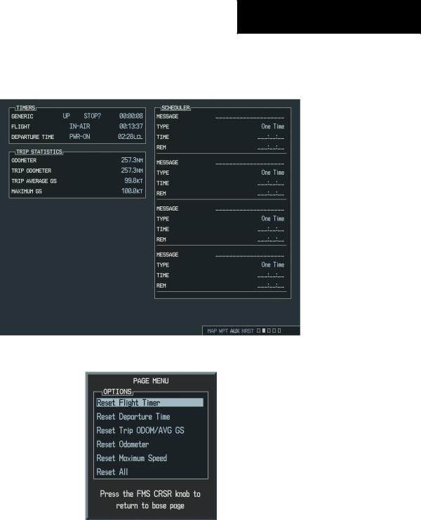
The Utility Page displays timers, trip statistics, and scheduler information for flight planning purposes.
Figure 7-75 Utility Page
|
Figure |
7-76 Utility Page Menu |
|
190-00498-00 Rev.A |
Garmin G1000 |
Pilot’s Guide for Cessna Nav III |
7-109 |

MULTI FUNCTION DISPLAY
Utility Page Operations
To set the generic timer direction (up, down):
1.Select the AUX UTILITY Page.
2.Press the FMS knob.The ‘GENERIC’ timer field is highlighted.
3.Turn the small FMS knob to display the ‘UP/ DOWN’ window.
4.Turn the FMS knob to select ‘UP’ or ‘DOWN’ and press the ENT key.
To start, stop, or reset the generic timer:
1.Select the AUX UTILITY Page.
2.Press the FMS knob. Turn the large FMS knob to select the ‘START?’ Field.
3.Press the ENT key to start, stop, or reset the timer.
To set the generic timer value:
1.Select the AUX UTILITY Page.
2.Press the FMS knob. Turn the large FMS knob to select the time field (hh/mm/ss).
3.Turn the small and large FMS knobs to set the desired time and press the ENT key.
To set the flight timer starting criteria (ground speed more then 30 knots, power on):
1.Select the AUX UTILITY Page.
2.Press the FMS knob. Turn the large FMS knob to select the ‘FLIGHT’ field.
3.Turn the smallFMSknob to display the selection window.
4.Turn the FMS knob to select either PWR-ON or GS>30KT and press the ENT key.
To set the departure timer starting criteria (ground speed more then 30 knots, power on):
1.Select the AUX UTILITY Page.
2.Press the FMS knob. Turn the large FMS knob to select the ‘DEPARTURE TIME’ field.
3.Turn the smallFMSknob to display the selection window.
4.Turn the FMS knob to select either PWR-ON or GS>30KT and press the ENT key.
To reset the flight timer:
1.Select the AUX UTILITY Page.
2.Press the MENU key. Turn the FMS knob to select ‘Reset Flight Timer’.
3.Press the ENT key.
To reset the departure timer:
1.Select the AUX UTILITY Page.
2.Press the MENU key. Turn the FMS knob to select ‘Reset Departure Time’.
3.Press the ENT key.
7-110 |
Garmin G1000 Pilot’s Guide for Cessna Nav III |
190-00498-00 Rev.A |

Trip Statistics
To reset trip statistics readouts:
1.Press the MENU key to display an options window with the following reset options:
•Reset Trip ODOM/AVG GS – Resets trip average ground speed readout and odometer
•Reset Odometer – Resets odometer readout only
•Reset Maximum Speed – Resets maximum speed readout only
•Reset All – Resets all trip statistics readouts
2.Turn the FMS knob to select the desired reset option and press the ENT key.
Scheduler
The scheduler feature displays reminder messages (such as “Change oil”, “Switch fuel tanks”, “Overhaul”, etc.). One-time, periodic, and event-based messages are allowed.One-timemessagesappearoncethetimerexpires and reappear each time the G1000 is powered on, until the message is deleted. Periodic messages automatically reset to the original timer value, once the message is displayed. Event-based messages do not use a timer, but rather a specific date and time.
•Name
•Type (event, one time, periodic)
•Date
•Time
•REM (remainder)
MULTI FUNCTION DISPLAY
To enter a name:
1.Select the AUX UTILITY Page.
2.Press the FMS knob. Turn the large FMS knob to select the flight scheduler name field.
3.Turn the FMS knobs to enter the desired name and press the ENT key.
To enter a type (event, one time, periodic)
1.Select the AUX UTILITY Page.
2.Press the FMS knob. Turn the large FMS knob to select the scheduler type field.
3.Turn the smallFMS knob to display the options list. Turn the FMS knobs to select the desired type and press the ENT key.
To enter a time:
1.Select the AUX Utility Page.
2.Press the FMS knob. Turn the large FMS knob to select the scheduler time field.
3.Turn the small and large FMS knobs to enter the desired time and press the ENT key.
To enter a date:
1.Select the AUX Utility Page.
2.Press the FMS knob. Turn the large FMS knob to select the scheduler date field.
3.Turn the small and large FMS knobs to enter the desired date and press the ENT key.
190-00498-00 Rev.A |
Garmin G1000 Pilot’s Guide for Cessna Nav III |
7-111 |