

7.4 TERRAIN PROXIMITY PAGE
CAUTION: Use of Terrain Proximity information for primary terrain avoidance is prohibited. The Terrain Proximity Map is intended only to enhance situational awareness. It is the pilot’s responsibility to provide terrain avoidance at all times.
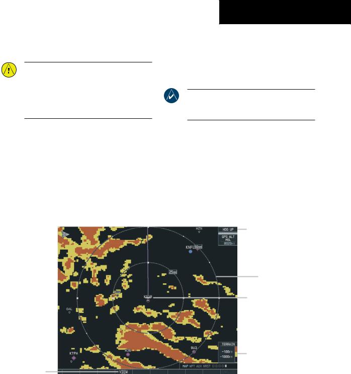
The Terrain Proximity Page displays the following:
•Current aircraft location
•Range marking rings (25 nm, 25/50 nm, 50/100 nm, and 100/200 nm)
•Heading Box (North Up, Track Up, DTK Up, HDG Up). Heading on the Terrain Proximity Page displays ‘HDG Up’ map data unless there is no valid heading
MULTI FUNCTION DISPLAY
•Terrain
•Terrain Range - Indicates the terrain elevation in colors relative to the aircraft altitude (Figure 7.4.2)
•Obstacles
NOTE: Terrain data is not displayed when the aircraft latitude is greater than 75 degrees north or 60 degrees south.
Page Orientation
Range Marking Ring
Current Aircraft
Location
Terrain Range
View Selection
Figure 7-19 Terrain Proximity Page
190-00498-00 Rev.A |
Garmin G1000 Pilot’s Guide for Cessna Nav III |
7-37 |

MULTI FUNCTION DISPLAY
TERRAIN PROXIMITY PAGE OPERATIONS
Therearetwoterrain/obstacleviewingoptionsavailable (relative to the position of the aircraft), a radar-like ARC (120°) display and a 360° default display.
To change the viewing mode between 360° and ARC:
1.Select the Terrain Proximity Page
2.Press the VIEW softkey. Press the ARC softkey.
3.To return to the 360 degree viewing display press the 360 softkey OR:
4.Press the MENU key. The page menu is displayed with ‘View Arc’ or ‘View 360º’ highlighted. Press the ENT key on the desired selection.
To change the map range on the Terrain Proximity Page:
1.Turn the joystick clockwise zoom out or turn the joystick counter-clockwise zoom in. Map ranges are 25 nm, 25/50 nm, 50/100 nm, and 100/200 nm.
Aircraft Altitude
100' Threshold
1000' AGL
Figure 7-20 Terrain Scale
7-38 |
Garmin G1000 Pilot’s Guide for Cessna Nav III |
190-00498-00 Rev.A |

DISPLAYING OBSTACLE DATA
The Terrain Proximity Page displays obstacle data with heights greater than 200 feet Above Ground Level (AGL) located at their geographical position location throughout the world. Obstacles are displayed in three levels. The G1000 will adjust colors on the Terrain Proximity Page automatically as the aircraft altitude changes. The display color patterns are as follows:
•SAFE
•CAUTION
•WARNING
GRAY-Safe
Obstacle data is displayed in gray when the obstacle height (MSL) is greater than 1000 feet below the current aircraft altitude.
YELLOW-Caution
Obstacle data is displayed in yellow when the obstacle height is 100 feet below MSL the current aircraft altitude to 1000 feet below the current aircraft altitude.
RED-Critical
Obstacle data is displayed in red when the obstacle height is at or above 100 feet Mean Sea Level (MSL) below the current aircraft altitude.
Obstacle Shapes
Obstacle shapes and defining criteria are found in Appendix F.
MULTI FUNCTION DISPLAY
NAVIGATION MAP DISPLAY CONDITIONS
The Map Setup Page Menu has ‘OBSTACLE’ and ‘TERRAIN feature On/Off options. The Terrain Proximity Page displays or does not display obstacles on the Navigation Map Page based on the selection of each as summarized in the table below:
TERRAIN |
OBSTACLE |
TERRAIN |
FEATURE |
FEATURE |
PROXIMITY PAGE |
OFF |
OFF |
NO OBSTACLES |
|
|
DISPLAYED |
|
|
|
OFF |
ON |
SAFE, CAUTION,AND |
|
|
WARNING OBSTACLES |
|
|
DISPLAYED |
|
|
|
ON |
OFF |
CAUTION AND |
|
|
WARNING OBSTACLES |
|
|
DISPLAYED |
|
|
|
ON |
ON |
SAFE, CAUTION,AND |
|
|
WARNING OBSTACLES |
|
|
DISPLAYED |
Note: Obstacles are only displayed at certain map zoom ranges, on certain map fields, and will only be displayed if an obstacle database is loaded on the SD card.
Note:The table above is only for the Navigation Map Page. The Terrain Proximity Page always shows ONLY caution and warning obstacles.
190-00498-00 Rev.A |
Garmin G1000 Pilot’s Guide for Cessna Nav III |
7-39 |
MULTI FUNCTION DISPLAY
7.5 TERRAIN AWARENESS & WARNING SYSTEM (TAWS)
DISPLAY (OPTIONAL)
NOTE: Terrain data is not displayed when the aircraft latitude is greater than 75 degrees north or 60 degrees south.
NOTE:TAWSoperationisonlyavailablewhenthe
G1000 is configured for a TAWS-B installation.
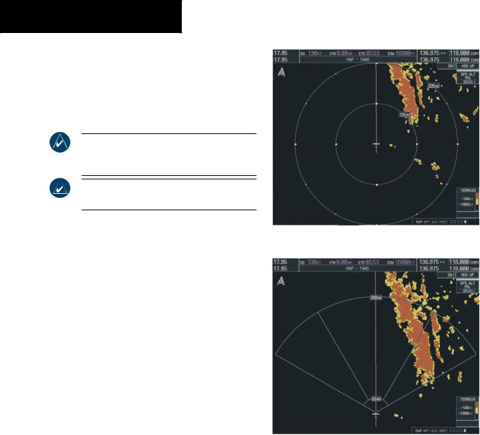
DISPLAYING TERRAIN ON THE TAWS PAGE
Figure 7-21 TAWS Page (360˚ View)
1.Turn the largeFMSknob to select the Map Page Group.
2.Turn the small FMS knob to select the TAWS Page, whichever is configured.
3.If desired,press the VIEW softkey to access the ARC and 360 softkeys. When the ARC softkey is pressed, a radar-like 120° view is displayed. Press the 360 softkey to return to the 360° default display.
4.Rotate the JOYSTICK clockwise to display a larger area or rotate counter-clockwise to display a smaller area.
Figure 7-22 TAWS Page (ARC View)
7-40 |
Garmin G1000 Pilot’s Guide for Cessna Nav III |
190-00498-00 Rev.A |
MULTI FUNCTION DISPLAY
Enable/Disable Aviation Data
1.While the TAWS Page is displayed, press the
MENU key.
2.Turn the small FMS knob to select “Show (or Hide) Aviation Data”.
3Press the ENT key.
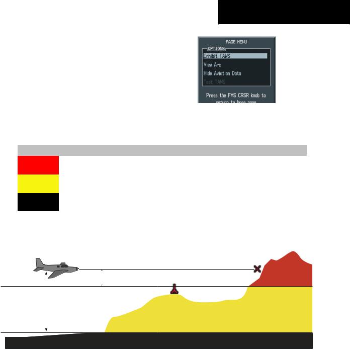
Figure 7-23 TAWS Page Menu
Color |
Terrain/Obstacle Location |
Alert Level |
|
Suggested Pilot Response |
Red |
Terrain/Obstacle is within 100’ or |
WARNING |
|
Initiate climb and/or turn away from |
above aircraft altitude. |
|
|
terrain/obstacle. |
|
|
|
|
||
Yellow |
Terrain/Obstacle is within 1000’ of |
CAUTION |
|
Be aware of surroundings. |
aircraft altitude. |
|
|
Be prepared to take action. |
|
|
|
|
||
Black |
Terrain/Obstacle is more than |
NO DANGER |
|
No action required. |
1000’ below aircraft altitude. |
|
|
|
|
|
|
|
|
|
|
Table 7-2 TAWS Color Definitions |
|
||
Potential Impact Point
Projected Flight Path
100' Threshold
Unlighted Obstacle
1000' AGL
Figure 7-24 TAWS Terrain/Obstacle Locations
190-00498-00 Rev.A |
Garmin G1000 Pilot’s Guide for Cessna Nav III |
7-41 |

MULTI FUNCTION DISPLAY
TAWS Inhibit
Flying VFR into an area where unique terrain exists could cause the system to annunciate a nuisance alert. When TAWS is inhibited, only FLTA and PDA alerts are disabled.
To Inhibit TAWS:
1.While the TAWS Page is displayed, press the
MENU key.
Forward Looking Terrain Avoidance (FLTA)
The Forward Looking Terrain Avoidance alert is composed of two sub-functions:
Reduced Required Terrain Clearance (RTC) and Reduced Required Obstacle Clearance (ROC)
This provides alerts when the aircraft flight path is above terrain and/or obstacles, yet is projected to come within minimum clearance values outlined in the
2.Turn the small FMS knob to select‘Inhibit following table. When an RTC or ROC alert is issued, a
TAWS’.
3. Press the ENT key.
To Enable TAWS:
1.While the TAWS Page is displayed, press the
MENU key.
2.Turn the small FMS knob to select ‘Enable TAWS’.
3.Press the ENT key.
Manual System Test
Asystemtestisautomaticallyperformedatpower-up. After sucessful completion of the test, “TAWS System Test, OK” will be heard.
The system test may also be initiated manually, but onlywhentheaircraftisontheground. Tomanuallyverify proper operation of the aural and visual annunciations of the system, perform the following steps.
1.While the TAWS Page is displayed, press the
MENU key.
2.Turn the small FMS knob to select ‘Test TAWS’.
3Press the ENT key. During the test‘TAWSTEST’ is displayed in the center of the TAWS Page.
When all is in working order, “TAWS System Test, OK” will be heard.
potential impact point is displayed on the TAWS Page as a yellow or red ‘X’.
Imminent Terrain Impact (ITI) and Imminent Obstacle Impact (IOI)
This provides alerts when the current aircraft altitude is below the elevation of terrain in the aircraft’s projected pathandtheverticalflightpathiscalculatedtocomewithin minimum clearence values outlined in the following table. ITI and IOI alerts are accompanied by a potential impact point displayed on the TAWS Page as a yellow or red ‘X’.
Phase of Flight |
Level Flight |
Descending |
Enroute |
700 ft. |
500 ft. |
|
|
|
Terminal |
350 ft. |
300 ft. |
Approach |
150 ft. |
100 ft. |
|
|
|
Departure |
100 ft. |
100 ft. |
|
|
|
During the final approach phase of flight, RTC/ROC/ ITI/IOI alerts are automatically inhibited when the aircraft isbelow200feetAGLwhilewithin0.5nmoftheapproach runway or is below 125 feet AGL while within 1 nm of the runway.
7-42 |
Garmin G1000 Pilot’s Guide for Cessna Nav III |
190-00498-00 Rev.A |
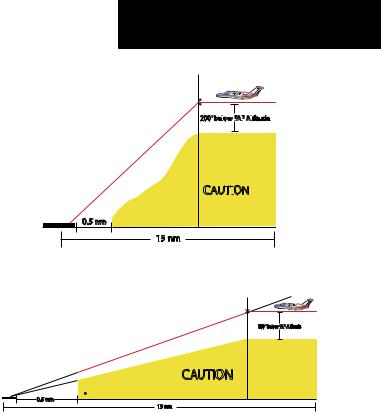
Premature Descent Alert (PDA)
A Premature Descent Alert is issued when the system detects that the aircraft is significantly below the normal approachpathtoarunway. ThePDAalertmodefunctions only during descent to land. There are three different scenarios to consider with PDA:
•No Approach Loaded - PDA alerting begins when theaircraftiswithin15nmofthedestinationairport andendswhentheaircraftiseither0.5nmfromthe runway threshold OR is at an altitude of 125 feet
•AGL while within 1 nm of the threshold. During the final descent, algorithms will set a threshold for alerting based on speed, distance, and other parameters.
•Non-Precision Approach Loaded - PDA alerting beginswhentheFAFistheactivewaypointANDthe aircraft is within 15 nm of the destination airport. Again, algorithms are used to set a threshold for alerting based upon various parameters. PDA alerting ends at 0.5 nm from the runway threshold OR at an altitude of 125 feet AGL while within 1 nm of the threshold.
•ILS Approach Loaded—PDA alerting begins when the FAF is the active waypoint AND the aircraft is within 15 nm of the destination airport. Prior to reaching the FAF, a PDA alert will be issued if the aircraft descends 200 feet below the FAF altitude. Oncetheaircraftinterceptstheglideslope,PDAwill alert the pilot if the aircraft descends 0.7 degrees below the glideslope. PDA alerting ends 0.5 nm from the runway threshold OR at an altitude of 125 feet AGL while within 1 nm of the threshold.
MULTI FUNCTION DISPLAY
Final Approach Fix 
200' bel
 ow F
ow F
 AF
AF
 Al
Al
 titude
Runway Threshol
CAUTI
 ON
ON
0.5 nm
15 nm
Figure 7-25 Non-Precision Approach PDA Alert Threshold
Glideslope Intercept
Final Approach Fix
200' bel
 ow F
ow F
 AF
AF
 Al
Al
 titude
Runway Threshold |
CAUTION |
|
|
|
PDA Alert is |
0.5 nm |
0.7 Below Glideslope |
|
15 nm
Figure 7-26 ILS Approach PDA Alert Threshold
190-00498-00 Rev.A |
Garmin G1000 Pilot’s Guide for Cessna Nav III |
7-43 |
MULTI FUNCTION DISPLAY
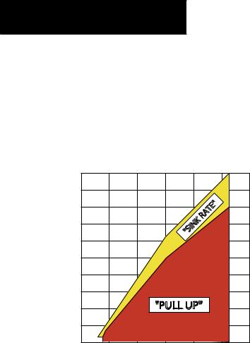
Excessive Descent Rate Alert (EDR)
The purpose of the Excessive Descent Rate alert is to provide suitable alerts when the aircraft is determined to beclosing(descending)uponterrainatanexcessivespeed. Figure 7-27 displays the correlation between height above terrain and descent rate, resulting in the two EDR alerts. EDR alerts have two levels of severity, caution (sink rate) and warning (pull-up).
|
5000 |
|
|
|
|
|
|
|
|
|
|
4500 |
|
|
|
|
|
|
|
|
|
|
4000 |
|
|
|
|
|
|
" |
|
|
|
|
|
|
|
|
E |
|
|
||
(Feet) |
|
|
|
|
|
T |
|
|
|
|
|
|
|
|
A |
|
|
|
|
||
|
|
|
|
R |
|
|
|
|
|
|
|
|
|
|
K |
|
|
|
|
|
|
3500 |
|
|
|
IN |
|
|
|
|
|
|
|
|
|
|
|
S |
|
|
|
|
|
Terrain |
|
|
|
|
" |
|
|
|
|
|
3000 |
|
|
|
|
|
|
|
|
|
|
2500 |
|
|
|
|
|
|
|
|
|
|
Above |
|
|
|
|
|
|
|
|
|
|
2000 |
|
|
|
|
|
|
|
|
|
|
|
|
|
|
|
|
|
|
|
|
|
Height |
1500 |
|
|
|
|
|
|
|
|
|
1000 |
|
|
"PULL UP" |
|
|
|
|
|
||
|
500 |
|
|
|
|
|
|
|
|
|
|
0 |
2000 |
4000 |
6000 |
8000 |
|
|
|
10000 |
12000 |
|
|
|
|
|
||||||
Descent Rate (FPM)
Figure 7-27 Excessive Descent Rate
Negative Climb Rate After Takeoff Alert (NCR)
The purpose of the Negative Climb Rate After Takeoff alert is to provide suitable alerts to the pilot when the system determines that the aircraft is losing altitude (closing upon terrain) after takeoff. The aural message “Don’t Sink” is given for NCR alerts, accompanied by an annunciation and a pop-up terrain alert on the display.
NCR is only activated during the departure phase of flight under the following conditions:
A)height above the terrain is less than 700 feet
B)the aircraft is less than 2 nm from the departure airport
C)heading change from the departure heading is less than 110 degrees.
“Five-Hundred” Aural Alert
The purpose of the aural alert message “Five-hundred” is to provide an advisory alert to the aircrew that the aircraft is five-hundred feet above terrain. When the aircraft descends within 500 feet of terrain, the aural message “Five-hundred” is heard. There are no display annunciations or pop-up alerts that accompany the aural message.
This function is enabled when the aircraft’s height above the terrain is more than 675 feet. It is disabled when the aircraft’s height above the terrain becomes less than 500 feet.
7-44 |
Garmin G1000 Pilot’s Guide for Cessna Nav III |
190-00498-00 Rev.A |
MULTI FUNCTION DISPLAY
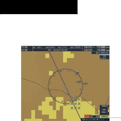
Displaying Terrain and Obstacles on the
Navigation Map
1.With the Navigation Map displayed, press the MAP softkey.
2.Press the TERRAINsoftkey. Terrain and obstacle proximity will now be displayed on the map.
Unlighted Obstacle |
Lighted Obstacle |
Unlighted Obstacle |
Lighted Obstacle |
Potential Impact Points |
(Height is less than |
(Height is less than |
(Height is greater than |
(Height is greater than |
|
1000’ AGL) |
1000’ AGL) |
1000’ AGL) |
1000’ AGL) |
|
|
|
|
|
|
Figure 7-28 TAWS Symbols
Range of topography elevation presently displayed on-screen
Maximum elevation of topography presently displayed on-screen
 Minimum elevation of topography presently displayed on-screen
Aircraft altitude
Ground elevation at present aircraft position
Figure 7-29 Topography Scale
190-00498-00 Rev.A |
Garmin G1000 Pilot’s Guide for Cessna Nav III |
7-45 |
MULTI FUNCTION DISPLAY
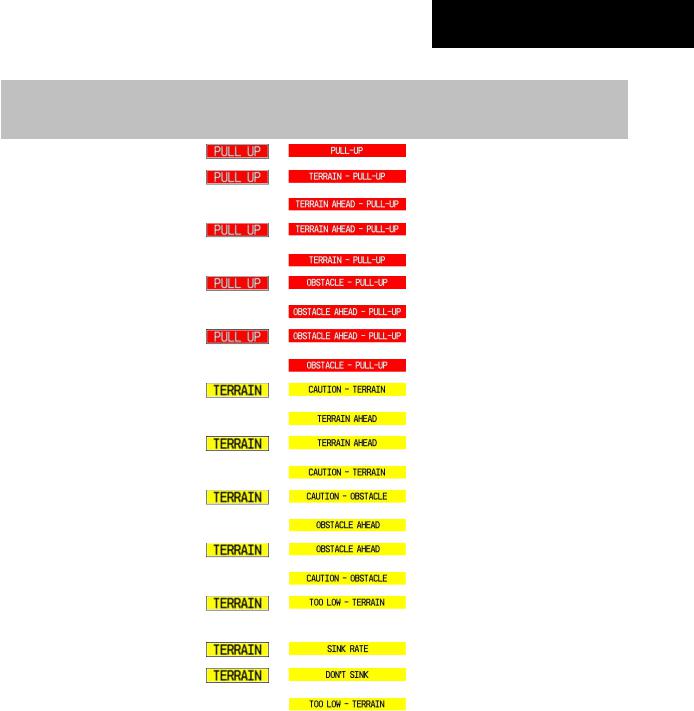
Pop-up Alerts |
TAWS Alerts Summary |
When a terrain or obstacle alert is issued, a pop-up window is displayed on the MFD with the appropriate alert.
Table 7-3 shows the possible TAWS alert types with corresponding annunciations and aural messages.
Pop Up Alert
Figure 7-30 Alert Pop-Up
Press the ENT key to display the TAWS Page, or press the CLR key to remain on the existing page.
7-46 |
Garmin G1000 Pilot’s Guide for Cessna Nav III |
190-00498-00 Rev.A |
|
|
|
|
|
MULTI FUNCTION DISPLAY |
|
|
|
|
|
|
|
|
|
|
|
|
|
|
|
|
|
PFD/MFD TAWS |
MFD Map Page |
|
|
|
|
Alert Type |
Page |
|
Aural Message |
|
|
|
Pop-Up Alert |
|
|
|||
|
|
Annunciation |
|
|
|
|
|
|
|
|
|
|
|
|
Excessive Descent RateWarning (EDR) |
|
|
|
“Pull Up” |
|
|
|
|
|
|
|
|
|
Reduced RequiredTerrain ClearanceWarn- |
|
|
|
“Terrain,Terrain; Pull Up, Pull Up” |
|
|
ing (RTC) |
|
or |
|
or |
|
|
|
|
|
“TerrainAhead, Pull Up;TerrainAhead, Pull Up” |
|
|
|
ImminentTerrain ImpactWarning (ITI) |
|
|
TerrainAhead, Pull Up;TerrainAhead,Pull Up” |
|
|
|
|
|
or |
|
or |
|
|
|
|
|
|
“Terrain,Terrain; Pull Up, Pull Up” |
|
|
Reduced Required Obstacle Clearance |
|
|
|
“Obstacle,Obstacle;Pull Up,Pull Up” |
|
|
Warning (ROC) |
|
or |
|
or |
|
|
|
|
|
“ObstacleAhead,Pull Up;ObstacleAhead,Pull Up” |
|
|
|
Imminent Obstacle ImpactWarning (IOI) |
|
|
“ObstacleAhead,Pull Up;ObstacleAhead,Pull Up” |
|
|
|
|
|
or |
|
or |
|
|
|
|
|
|
“Obstacle,Obstacle;Pull Up,Pull Up” |
|
|
Reduced RequiredTerrain Clearance Caution |
|
|
|
“Caution,Terrain; Caution,Terrain” |
|
|
(RTC) |
|
or |
|
or |
|
|
|
|
|
|
“TerrainAhead;TerrainAhead” |
|
|
ImminentTerrain Impact Caution (ITI) |
|
|
|
“TerrainAhead;TerrainAhead” |
|
|
|
|
or |
|
or |
|
|
|
|
|
|
“Caution,Terrain; Caution,Terrain” |
|
|
Reduced Required Obstacle Clearance |
|
|
|
“Caution, Obstacle; Caution, Obstacle” |
|
|
Caution (ROC) |
|
or |
|
or |
|
|
|
|
|
|
“ObstacleAhead; ObstacleAhead” |
|
|
Imminent Obstacle Impact Caution (IOI) |
|
|
|
“ObstacleAhead; ObstacleAhead” |
|
|
|
|
or |
|
or |
|
|
|
|
|
|
“Caution, Obstacle; Caution, Obstacle” |
|
|
Premature DescentAlert Caution (PDA) |
|
|
|
“Too Low,Terrain” |
|
|
|
|
|
|
|
|
|
Altitude Callout“500” |
None |
None |
|
“Five-Hundred” |
|
|
Excessive Descent Rate Caution (EDR) |
|
|
|
“Sink Rate” |
|
|
|
|
|
|
|
|
|
Negative Climb Rate Caution (NCR) |
|
|
|
“Don’t Sink” |
|
|
|
|
or |
|
or |
|
|
|
|
|
|
“Too Low,Terrain” |
|
|
|
Table 7-3 TAWS Alert Summary |
|
|
|
|
190-00498-00 Rev.A |
Garmin G1000 Pilot’s Guide for Cessna Nav III |
7-47 |
||||

MULTI FUNCTION DISPLAY
The following system status annunciations may also be issued.
|
PFD/MFD TAWS |
MFD |
|
|
Alert Type |
Page |
Aural Message |
||
Pop-Up Alert |
||||
|
Annunciation |
|
||
|
|
|
||
TAWS SystemTest Fail |
|
None |
“TAWS System Failure” |
|
|
|
|
|
|
TAWSAlerting is disabled |
|
None |
None |
|
|
|
|
|
|
No GPS position or excessively degraded |
|
None |
“TAWS NotAvailable” |
|
GPS signal |
|
|
|
|
SystemTest in progress |
|
None |
None |
|
|
|
|
|
|
SystemTest pass |
None |
None |
“TAWS SystemTest OK” |
Table 7-4 TAWS Status Summary
7-48 |
Garmin G1000 Pilot’s Guide for Cessna Nav III |
190-00498-00 Rev.A |