


6.2 ENGINE PAGE
The Engine Page is the default page for the EIS page group, and is accessed the first time the ENGINE softkey is pressed from the MFD. The Engine Page can be displayed after viewing other EIS pages by pressing the ENGINE softkey.
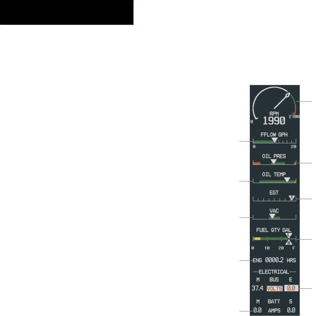
Atthetopofthepagearethedialgauge(s). Beneathare horizontal bar indicators and readouts for critical engine and electrical parameters.
Fuel Flow (FFLOW GPH)
The Fuel Flow Indicator displays current fuel flow in gallons per hour (GPH). Green indicates normal fuel flow, while any area beyond the green band is an indication of abnormal fuel flow.
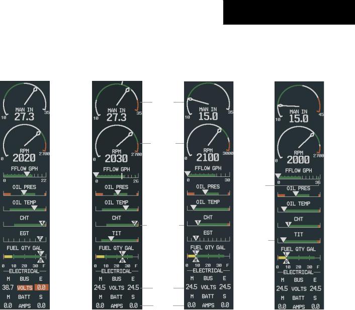
For turbocharged aircraft, the Fuel Flow Indicator displays a small stand-alone green band indicating maximum takeoff fuel flow, and a wide, vertical white tick mark indicating the maximum cruise fuel flow (Model T182 only).
Oil Pressure (OIL PRES)
The Oil Pressure Indicator displays the pressure of the oil supplied to the engine in pounds per square inch (PSI).
•Green – Normal operating range
•Red – Warning (minimum and maximum)
Oil Temperature (OIL TEMP)
The Oil Temperature Indicator displays the engine oil temperature in degrees Fahrenheit.
•Green – Normal operating range
•Red – Warning
ENGINE INDICATION SYSTEM
Cylinder HeadTemperature (CHT) - Models 182,T182,
206,T206
The Cylinder Head Temperature (CHT) Indicator displays the temperature of the hottest cylinder in degrees Fahrenheit. The number of the hottest cylinder appears in the triangle.
•Green – Normal operating range
•Red – Warning
Exhaust Gas Temperature (EGT)-Normally-Aspirated Aircraft
For normally-aspirated aircraft, the Exhaust Gas Temperature (EGT) Indicator displays the exhaust gas temperature of the hottest cylinder in degrees Fahrenheit. The number of the associated cylinder is indicated in the triangle. There are no color bands associated with this indicator.
TurbineInletTemperature(TIT)-TurbochargedAircraft
NOTE:The pilot should refer to theAircraft Flight
Manual (AFM) for limitations.
The Turbine Inlet Temperature (TIT) Indicator displays the temperature at the turbine inlet in degrees Fahrenheit.
•Green – Normal operating range
•Red – Warning
Vacuum Pressure (VAC) - Model 172
Vacuum pressure is shown on a horizontal bar indicator. The normal operating range is indicated by the green band.
190-00498-00 Rev.A |
Garmin G1000 Pilot’s Guide for Cessna Nav III |
6-3 |
ENGINE INDICATION SYSTEM
Engine Hours (ENG HRS) - Model 172
Engine hours are shown as a numeric readout beneath the Fuel Quantity Indicator.
Voltmeter (VOLTS)
The Voltmeter displays the main and essential bus voltage.
•White – Normal
•Yellow – Caution (low and high)
•Red – Warning (minimum and maximum)
Ammeter (AMPS)
The Ammeter displays the main and standby battery load in amperes.
•White – Normal
•Yellow – Caution
Tachometer
Fuel Flow
Indicator
Oil Pressure
Indicator
Oil Temperature
Indicator
Exhaust Gas
Temperature
Indicator
Vacuum
Pressure
Indicator
Fuel Quantity
Indicator
Engine Hours
(Tach)
Voltmeter
Ammeter
Figure 6-4 Engine Page (172)
6-4 |
Garmin G1000 Pilot’s Guide for Cessna Nav III |
190-00498-00 Rev.A |
ENGINE INDICATION SYSTEM
|
|
Cruise |
|
|
|
|
|
|
|
|
|
|
|
|
|
|
|
||||
|
|
Manifold |
|
|
|
|||||
|
|
Pressure |
|
Manifold |
||||||
|
|
|
|
|
|
|
|
|
Pressure |
|
|
|
|
|
|
|
|
|
|
Gauge |
|
|
|
|
|
|
|
|
|
|
Tachometer |
|
|
|
|
|
|
|
|
|
|
Fuel Flow |
|
|
|
Cruise |
|
|
|
|
Indicator |
|
||
|
|
|||||||||
|
|
Fuel Flow |
|
|
|
|
Oil Pressure |
|||
|
|
|
|
|
|
|
|
|
||
|
|
|
|
|
|
|
|
|
Indicator |
|
|
|
|
|
|
|
|
|
|
Oil Temperature |
|
|
|
|
|
|
|
|
|
|
Indicator |
|
|
|
|
|
|
|
|
|
|
Cylinder Head |
|
|
|
|
|
|
|
|
|
|
Temperature |
|
|
|
Exhaust Gas |
|
Indicator |
||||||
|
|
|
|
|
||||||
|
|
Temperature |
|
|
|
|||||
|
|
|
|
|
||||||
|
|
Indicator |
|
Fuel Quantity |
||||||
|
|
|
|
|
|
|
|
|
||
|
|
|
|
|
|
|
|
|
Indicator |
|
|
|
|
|
|
|
|
|
|
Voltmeter |
|
Model 182 |
|
|
|
Model T182 |
|
Ammeter |
Model 206 |
|||
|
|
|
|
|
||||||
|
|
|
|
Figure 6-5 |
Engine Page (182,T182, 206,T206) |
|||||
Maximum
Takeoff
Fuel Flow
Turbine Inlet
Temperature
Indicator
Model T206
190-00498-00 Rev.A |
Garmin G1000 Pilot’s Guide for Cessna Nav III |
6-5 |

ENGINE INDICATION SYSTEM
6.3 LEAN PAGE |
Cylinder Select |
NOTE: The pilot should follow the engine manufacturer’s recommended leaning procedures in the Aircraft Flight Manual (AFM).
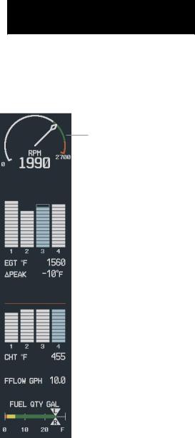
The Lean is accessed by pressing the LEAN softkey on the MFD from within the EIS page group. The Lean Page provides information and a user interface for performing engine leaning.
The engine gauge(s) and Fuel Quantity Indicator remain on the Lean Page. The Fuel Flow is listed as a numeric readout.
EGT and CHT Bar Graphs
EGTandCHTforallcylindersaredisplayedgraphically and the numeric readouts for the selected cylinder are provided under the EGT and CHT bar graphs. By default, the hottest cylinder is selected on the EGT and CHT bar graphs. Bars are color-coded as follows:
Cyan(lightblue)–SelectedCylinder
White–Normal
Yellow–Caution(CHTonly)
Red–Warning(CHTonly)
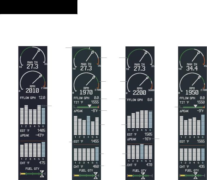
For turbocharged aircraft, the TIT Indicator and readout are shown above the EGT bar graph.
The pilot can utilize the CYL SLCT and ASSIST softkeys to obtain information about specific cylinders.
NOTE: The CYL SLCT softkey is disabled when the ASSIST softkey is pressed.
The CYL SLCT softkey becomes available after the LEAN softkey is pressed. The CYL SLCT softkey can be utilized to obtain EGT and CHT information about a particularcylinder. PressingtheCYLSLCTsoftkeycycles through the cylinders.
This softkey is disabled when a cylinder experiences a caution (yellow bar on graph) or warning (red) condition, and remains disabled until the temperature returns to normal (white).
Assist
The ASSIST softkey becomes available after pressing theLEANsoftkey. TheASSISTsoftkeyaidsintheleaning process by identifying the peak of the first cylinder whose temperaturefalls. Thiscylinder’sbarontheEGTandCHT bar graphs is highlighted in cyan as the selected cylinder. If the temperature of the peaked cylinder exceeds the peak value, the peak value is not updated.
Monitoring of the cylinder continues until the ASSIST softkey is pressed again. Pressing the ASSIST again will disable lean assist, remove the peak block from the bar graph and the ∆PEAK Readout, and returns the readout to seeking the hottest cylinder.
6-6 |
Garmin G1000 Pilot’s Guide for Cessna Nav III |
190-00498-00 Rev.A |
Normally Aspirated Aircraft
When a cylinder peaks, its peak is represented by a hollow block on the EGT Bar Graph. The EGT Readout forthepeakedcylinder,indicatedincyan,appearsdirectly beneath the bar graph. The system automatically switches to the first peak obtained and displays the temperature deviation from peak (∆PEAK) in degrees Fahrenheit below the EGT Readout.
Turbocharged Aircraft
Leaning is done with reference to the Turbine Inlet Temperature (TIT) Indicator. When the temperature peaks, the numeric readout (∆PEAK) appears below the TIT Indicator and displays the difference between peak and current TITs, in degrees Fahrenheit. If a peak is not displayed, underscores are shown until one is established.
ENGINE INDICATION SYSTEM
Tachometer
|
|
|
|
|
|
|
|
Hollow Block |
Exhaust Gas |
|
|
|
Representing Peak |
||||
|
|
|
||||||
|
|
|
|
|
|
|||
Temperature |
|
|
|
|
|
|
|
|
|
|
|
|
|
|
|
||
Bar Graph |
|
|
|
|
|
|
||
|
|
|
|
|
|
|
|
EGT Readout |
Temperature |
|
|
|
|
|
For Selected |
||
|
|
|
|
|
||||
|
|
|
|
|
Cylinder |
|||
Deviation |
|
|
|
|
|
|
||
|
|
|
|
|
|
|
||
From Peak |
|
|
|
|
|
|
||
|
|
|
|
|
|
Cylinder Head |
||
|
|
|
|
|
|
|
|
Temperature |
|
|
|
|
|
|
|
||
|
|
|
|
|
|
|
|
Bar Graph |
CHT Readout |
|
|
|
|
|
|
||
For Selected |
|
|
|
|
|
|
|
|
|
|
|
|
|
|
|
||
Cylinder |
|
|
|
|
|
|
||
Fuel Quantity |
|
|
|
|
|
Fuel Flow |
||
|
|
|
|
|||||
|
|
|
|
|
|
|||
Indicator |
|
|
|
|
|
|
|
|
Figure 6-6 Lean Page (172)
190-00498-00 Rev.A |
Garmin G1000 Pilot’s Guide for Cessna Nav III |
6-7 |
ENGINE INDICATION SYSTEM
Cruise
Manifold
Pressure Manifold
Pressure
Gauge
Hollow Block
Represents Peak
EGT Readout
For Selected
Cylinder
Model 182
Tachometer
Fuel Flow
Temperature
Deviation
From Peak
Exhaust Gas
Temperature
Bar Graph
|
|
Cylinder Head |
|
|
|
Temperature |
|
|
|
Bar Graph |
|
|
|
CHT Readout |
|
|
|
For Selected |
|
|
|
Cylinder |
|
|
|
Fuel Quantity |
|
|
|
Indicator |
|
Model T182 |
|
|
Model 206 |
Figure 6-7 |
Lean Page (182,T182, 206,T206) |
||
Turbine Inlet
Temperature
Indicator
Temperature
Deviation
From Peak
Model T206
6-8 |
Garmin G1000 Pilot’s Guide for Cessna Nav III |
190-00498-00 Rev.A |