

1.3 PFD/MFD CONTROLS
1 |
2 |
3 |
4 |
5 |
|
17 |
|
Figure 1-3 PFD/MFD Controls |
1 |
NAV VOL/ID Knob |
10 |
Direct-to Key |
2 |
NAV Frequency Toggle Key |
11 |
Flight Plan Key |
3 |
NAV Knob |
12 |
Clear Key |
4 |
Heading Knob |
13 |
Flight Management System Knob |
5 |
Range Joystick |
14 |
Menu Key |
6 |
Course/Baro Knob |
15 |
Procedure Key |
7 |
COM Knob |
16 |
Enter Key |
8 |
COM Frequency Toggle Key |
17 |
Altitude Knob |
9COM VOL/SQ Knob
SYSTEM OVERVIEW
6 |
7 |
8 |
9 |
10 |
14 |
11 |
15 |
12 |
16 |
13 |
|
190-00498-00 Rev.A |
Garmin G1000 Pilot’s Guide for Cessna Nav III |
1-7 |

SYSTEM OVERVIEW
The G1000 controls and keys have been designed to simplify the operation of the system and minimize workloadaswellasthetimerequiredtoaccesssophisticated functionality. The following list provides an overview of the controls located on the display bezel.
•(1) NAV VOL/ID Knob – Controls the NAV audio level. Press to toggle the Morse code identifier ON and OFF. Volume level is shown in the field as a percentage.
•(2) NAV Frequency Toggle Key – Toggles the standby and active NAV frequencies.
•(3)DualNAVKnob–TunestheMHz(largeknob) and kHz (small knob) standby frequencies for the NAVreceiver. Presstotogglethetuningcursor(cyan box) between the NAV1 and NAV2 fields.
•(4) Heading Knob – Manually selects a heading when turned. Synchronizes the heading bug with the compass lubber line when pressed.
•(5)Joystick–Changesthemaprangewhenrotated. Activates the map pointer when pressed.
•(6) CRS/BARO Knob – The large knob sets the altimeter barometric pressure and the small knob adjusts the course. The course is only adjustable when the HSI is in VOR1, VOR2, or OBS/SUSP mode. Pressing this knob centers the CDI on the currently selected VOR.
•(7)DualCOMKnob–TunestheMHz(largeknob) and kHz (small knob) standby frequencies for the COM transceiver. Pressing this knob toggles the tuning cursor (cyan box) between the COM1 and COM2 fields.
•(8) COM Frequency Toggle Key – Toggles the standby and active COM frequencies. Pressing and holdingthiskeyfortwosecondsautomaticallytunes theemergencyfrequency(121.5MHz)intheactive frequency field.
•(9) COM VOL/SQ Knob – Controls COM audio level. Pressing this knob turns the COM automatic squelchONandOFF. Audiovolumelevelisshown in the field as a percentage.
•(10) Direct-to Key ( ) – Allows the user to enter a destination waypoint and establish a direct course to the selected destination (specified by the identifier, chosen from the active route, or taken from the map cursor position).
•(11)FPLKey–DisplaystheactiveFlightPlanPage for creating and editing the active flight plan, or for accessing stored flight plans.
•(12) CLR Key (DFLT MAP) – Erases information, cancelsanentry,orremovespagemenus. Todisplay theNavigationMapPageimmediately,pressandhold CLR (MFD only).
•(13)DualFMSKnob–Usedtoselectthepagetobe viewed(onlyontheMFD). Thelargeknobselectsa pagegroup(MAP,WPT,AUX,NRST),whilethesmall knob selects a specific page within the page group. Pressing the small knob turns the selection cursor ON and OFF. When the cursor is ON, data may be enteredinthedifferentwindowsusingthesmalland large knobs. The large knob is used to move the cursor on the page, while the small knob is used to selectindividualcharactersforthehighlightedcursor location. When the G1000 displays a list that is too longforthedisplayscreen,ascrollbarappearsalong therightsideofthedisplay,indicatingtheavailability ofadditionalitemswithintheselectedcategory. Press the FMS/PUSH CRSR knob to activate the cursor and turn the large FMS knob to scroll through the list.
•(14) MENU Key – Displays a context-sensitive list of options. This list allows the user to access additional features, or to make setting changes that relate to certain pages.
1-8 |
Garmin G1000 Pilot’s Guide for Cessna Nav III |
190-00498-00 Rev.A |

•(15) PROC Key – Selects approaches, departures and arrivals from the flight plan. If a flight plan is used, available procedures for the departure and/or arrival airport are automatically suggested. If a flight plan is not used, the desired airport and the desiredproceduremaybeselected. Thiskeyselects IFR departure procedures (DPs), arrival procedures (STARs) and approaches (IAPs) from the database and loads them into the active flight plan.
•(16) ENT Key – Accepts a menu selection or data entry. This key is used to approve an operation or complete data entry. It is also used to confirm selections and information entries.
•(17) Dual ALT Knob – Sets the reference altitude in the box located above the Altimeter. The large knob selects the thousands, while the small knob selects the hundreds.
 NOTE: The selected COM (displayed in green) is controlled by the COM MIC key on theAudio Panel (GMA 1347).
SYSTEM OVERVIEW
1.4 SECURE DIGITAL CARDS
The GDU 1040 data card slots use Secure Digital (SD) cards. SD cards are used for aviation database updates and terrain database storage.
To install an SD card:
1.Insert the SD card in the SD card slot located on the right side of the display bezel (the front of the card should be flush with the face of the display bezel).
To remove an SD card:
1.Gently press on the SD card to release the spring latch and eject the card.
 NOTE: Please refer to the Pilot’s Guide Appendices for instructions on updating the aviation database.
190-00498-00 Rev.A |
Garmin G1000 Pilot’s Guide for Cessna Nav III |
1-9 |
SYSTEM OVERVIEW
1.5 SYSTEM POWER-UP
The G1000 system is integrated with the aircraft electricalsystemandreceivespowerdirectlyfromelectrical busses. The Garmin G1000 PFD/MFD and supporting sub-systems include both power-on and continuous builtin test features that exercise the processor, RAM, ROM, external inputs and outputs to provide safe operation.
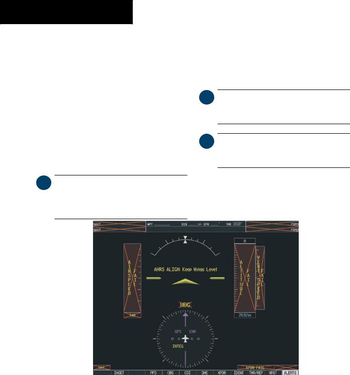
Whilethesystembeginstoinitialize,testannunciations are displayed to the pilot at power-up, as shown in the following figure. All system annunciations should be cleared within one (1) minute of power-up. The Audio Panel also annunciates all bezel lights briefly upon powerup.
 NOTE: Please see the Aircraft Flight Manual (AFM) for specific procedures concerning avionics power application and emergency power supply operation.
On the PFD, the AHRS system displays the ‘AHRS ALIGN:KeepWingsLevel’messageandbeginstoinitialize. The AHRS should display valid attitude and heading fields within one (1) minute of power-up. The AHRS can align itself both while taxiing and during level flight.
 NOTE: Please refer to the Pilot’s Guide Appendices for AHRS initialization bank angle limitations.
 NOTE: See theAnnunciations andAlerts Pilot’s Guide for additional information regarding system annunciations and alerts.
Figure 1-4 PFD Initialization
1-10 |
Garmin G1000 Pilot’s Guide for Cessna Nav III |
190-00498-00 Rev.A |

When the MFD powers up, the MFD Power-up Page displays the following information:
•System version
•Copyright
•Checklist filename
•Land database name and version
•Obstacle database name and version
•Terrain database name and version
•Aviation database name, version and effective dates
SYSTEM OVERVIEW
When this information has been reviewed for currency (to ensure that no databases have expired), the pilot is prompted to continue. Current database information is displayed with the valid operating dates, cycle number and database type.
Press the ENT key to acknowledge this information and proceed to the Navigation Map Page. When the system has acquired a sufficient number of satellites to determine a position, the Navigation Map Page appears, showing the aircraft current position.
Figure 1-5 MFD Power-up Page
190-00498-00 Rev.A |
Garmin G1000 Pilot’s Guide for Cessna Nav III |
1-11 |