
- •1.1 System Description
- •1.2 Line Replaceable Units
- •1.3 PFD/MFD Controls
- •1.4 Secure Digital Cards
- •1.5 System Power-up
- •1.6 Display Backlighting
- •1.7 System Operation
- •Normal Mode
- •Reversionary Mode
- •AHRS Operation
- •2.1 Introduction
- •2.2 Backlighting
- •2.3 Softkey Function
- •2.4 Flight Instruments
- •Airspeed Indicator
- •Attitude Indicator
- •Altimeter
- •Vertical Speed Indicator
- •Horizontal Situation Indicator
- •Communication Frequency Window
- •Navigation Frequency Window
- •Navigation Status Bar
- •Transponder Status Bar
- •2.6 Supplemental Flight Data
- •Outside Air Temperature Box
- •System Time Box
- •Traffic Annunciation
- •Terrain Proximity
- •Terrain Awareness and Warning System (TAWS) (Optional)
- •Inset Map
- •Working with Menus
- •Auxiliary Window Keys
- •Auxiliary Windows
- •2.7 Reversionary Mode
- •2.8 Alerts and Annunciations
- •Alerts Window
- •Annunciation Window
- •Softkey Annunciations
- •3.1 Overview
- •Windows and Fields
- •Radio Selection
- •Controls
- •Tuning Box
- •Switching Between Radios
- •Manually Tuning a Frequency
- •Radio Indicators
- •Volume
- •Frequency Transfer Arrow
- •3.2 COM Operation
- •Frequency Spacing
- •Automatic Squelch
- •Selecting a COM Radio
- •Emergency Frequency (121.500 MHz)
- •Quick-Tuning and Activating 121.500 MHz
- •Stuck Microphone
- •3.3 NAV Operation
- •Frequency Range
- •Morse Code Identifier
- •NAV Radio Selection for Navigation
- •ADF/DME Tuning
- •DME Tuning
- •3.4 Frequency Auto-tuning
- •Auto-tuning on the PFD
- •Auto-tuning on the MFD
- •Auto-Tuning on Approach Activation (NAV Frequencies)
- •4.1 Transponder Description
- •Transponder Softkeys
- •Transponder Status Bar
- •Mode S Features
- •Traffic Information Service (TIS)
- •4.2 Operation
- •Mode Selection
- •Code Selection
- •IDENT Function
- •5.1 Audio Panel Description
- •Transceivers
- •Mono/Stereo Headsets
- •Unmuted/Unswitched Inputs
- •Front Panel Controls
- •5.2 Operation
- •Power-up and Fail-safe Operation
- •Key Annunciators
- •Lighting
- •Transceiver Keys
- •Optional COM Muting
- •Split COM Function
- •PA Function
- •Speaker
- •Marker Beacon Receiver
- •Marker Beacon Volume Adjustment
- •Navigation Radios
- •Intercom System (ICS) Isolation
- •Intercom Volume and Squelch
- •Entertainment Inputs
- •GDL 69/69A XM Radio System
- •Master Avionics Squelch (MASQ)
- •Digital Clearance Recorder with Playback Capability
- •Reversionary Mode
- •6.1 Introduction
- •EIS Pages
- •EIS Indicators
- •EiS Page Reversion
- •6.2 Engine Page
- •6.3 Lean Page
- •6.4 System Page
- •7.1 Introduction
- •Description
- •Reversionary Mode
- •Optional Equipment
- •MFD Power-up
- •MFD Backlighting
- •MFD Softkeys
- •Electronic Checklists (optional)
- •MFD Page Groups
- •Working With Menus
- •7.2 Navigation Map Page
- •Navigation Map Page Operations
- •7.3 Traffic Map Page
- •TIS Symbology
- •Traffic Map Page Operations
- •7.4 Terrain Proximity Page
- •Terrain Proximity Page Operations
- •Displaying Obstacle Data
- •Navigation Map Display Conditions
- •Displaying Terrain on the TAWS Page
- •7.6 Direct-to Navigation
- •Direct-to Navigation Operations
- •7.7 Flight Plans
- •Active Flight Plan Page
- •Active Flight Plan Page Options
- •Flight Plan Catalog Page
- •Flight Plan Catalog Page Operations
- •Vertical Navigation (VNAV) Page
- •7.8 Procedures
- •Arrivals and Departures
- •Approaches
- •G1000 Navigational Guidance for Approaches
- •Selecting Approaches
- •7.9 Waypoint Page Group
- •AIRPORT Information Page (INFO)
- •Airport Frequency Information Field
- •AIRPORT Information Page Options
- •Departure Information Page (DP)
- •Arrival Information Page (STAR)
- •Approach Information Page
- •Intersection Information Page
- •NDB Information Page
- •VOR Information Page
- •User Waypoint Information Page
- •Creating User Waypoints
- •Modifying User Waypoints
- •User Waypoint Information Page Options
- •7.10 Auxiliary Page Group
- •Trip Planning Page
- •GPS Status Page
- •System Setup Page
- •System Status Page
- •7.11 Nearest Page Group
- •Navigating to a Nearest Waypoint
- •Nearest Intersections Page
- •Nearest NDB Page
- •Nearest VOR Page
- •Nearest User Waypoint Page
- •Nearest Frequencies Page
- •Nearest Airspaces Page
- •8.1 Introduction
- •8.2 WX-500 Stormscope
- •Displaying Stormscope Lightning Data on the Navigation Map Page
- •Stormscope Page
- •8.3 Traffic Advisory System
- •Displaying and Configuring TAS Traffic on the Navigation Map Page
- •Traffic Map Page
- •Failure Response
- •Description of Traffic Advisory Criteria
- •User-Initiated Test
- •TAS Voice Announcements
- •Switching Between Standby and Various Operating Modes
- •Altitude Display Mode
- •Traffic Map Page Display Range
- •8.4 XM Weather and XM Radio
- •Introduction
- •XM Weather
- •Weather Product Symbols
- •XM Digital Audio Entertainment
- •XM Radio Page
- •9.1 Introduction
- •9.2 Alert Level Definitions
- •9.4 CO Guardian Messages
- •9.6 G1000 System Annunciations
- •Appendices
- •Aviation Database
- •Terrain and Obstacle Databases
- •Introduction
- •TIS vs. TCAS
- •TIS Limitations
- •Airport
- •NAVAIDS
- •Basemap
- •Traffic
- •Lightning Strike
- •Impact Points (TAWS Only)
- •Miscellaneous
- •Line Symbols
- •Obstacle database
- •Terrain Color Chart
- •GMA 1347 Audio Panel
- •GIA 63 Integrated Avionics Units
- •GDC 74A Air Data Computer
- •GTX 33 Mode S Transponder
- •GEA 71 Engine/Airframe Unit
- •GDL 69/69A Weather Data Link
- •GRS 77 AHRS
- •Index

NAV/COM
3.3 NAV OPERATION |
NAV RADIO SELECTION FOR NAVIGATION |
FREQUENCY RANGE
TheNAVradiosreceiveintheVOR/ILSfrequencyrange of 108.00 to 117.95 MHz with 50 kHz spacing. The NAV Frequency window displays the following information:
•NAV1 and NAV2 active and standby frequencies
•NAV1 and NAV2 identifier indication (if the Morse code identifier is received by the system)
•Color-coded indication of the selected NAV radio
•Morse code identifier status
MORSE CODE IDENTIFIER
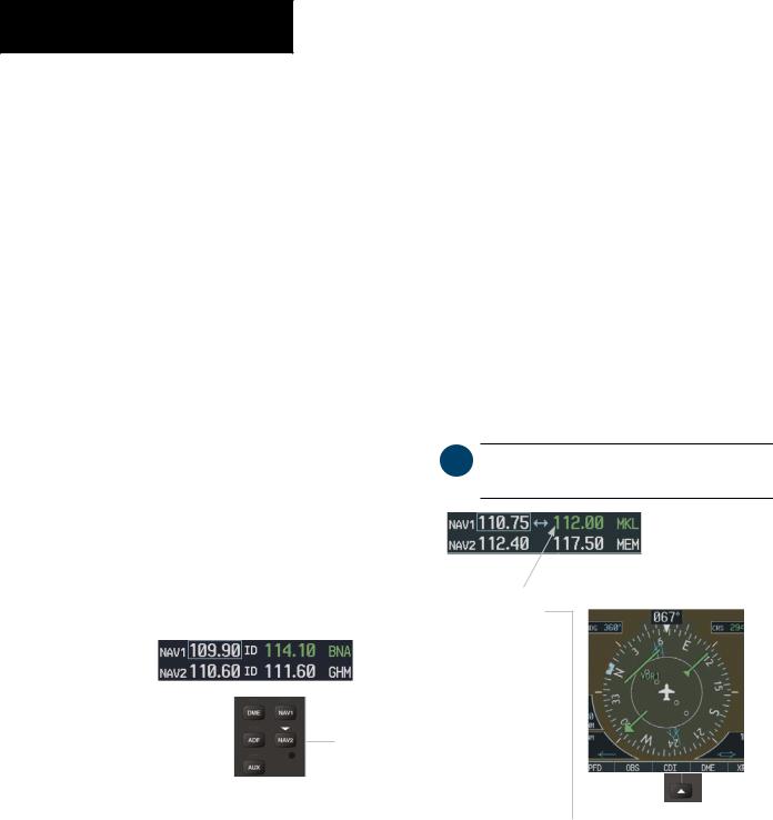
Press the VOL/PUSH ID knob to turn the Morse code identifier ON and OFF. When the identifier is ON, a white ID indication appears to the left of the active NAV frequency, and the Morse code is heard on the NAV audio. The VOR/LOC Morse code identifier is displayed next to the active NAV frequency.
WhentheidentifierisOFF,theIDindicationdisappears and the Morse code is off.
NAV audio is available with the ID filtered out for listening to HIWAS and FSS transmissions on VOR stations.
The desired NAV radio is selected for navigation by pressing the CDI softkey located on the PFD. The three navigation modes that can be selected are:
•VOR1 (or LOC1) – If NAV1 is selected, a single green arrow (shown) labeled either ‘VOR1’ or ‘LOC1’isdisplayedontheHSIandtheactiveNAV1 frequency is displayed in green.
•VOR2 (or LOC2) – If NAV2 is selected, a double green arrow (not shown) labeled either ‘VOR2’ or ‘LOC2’isdisplayedontheHSIandtheactiveNAV2 frequency is displayed in green.
•GPS – If GPS mode is selected, a single magenta arrow (not shown) appears on the HSI and neither NAV radio is selected.
NOTE: In GPS mode, both active NAV frequencies are displayed in white.
The NAV radio is selected by the CDI softkey.
NAV2 radio is selected on the audio panel. The Morse code identifier for the GHM VOR can be heard.
NAV section of the audio panel
Figure 3-16 |
Morse Code Identifier Audio |
|
|
|
|
|
|
|
|
|
Figure 3-17 |
Selecting a NAV Radio |
||
3-8 |
Garmin G1000 Pilot’s Guide for Cessna Nav III |
|
|
190-00498-00 Rev.A |

ADF/DME TUNING
The optional BendixKing KR-87 ADF is not tuned by the G1000 system. Refer to the Honeywell BendixKing KR 87 ADF Operators manual for ADF information. ADF volume is also adjusted through the KR 87.
TheG1000systemtunestheoptionalDMEtransceiver. The UHF DME frequency is paired with a VHF NAV frequency, providing DME distance information. Frequency pairing is automatic and only the VHF NAV frequency is shown on the display.
DME TUNING
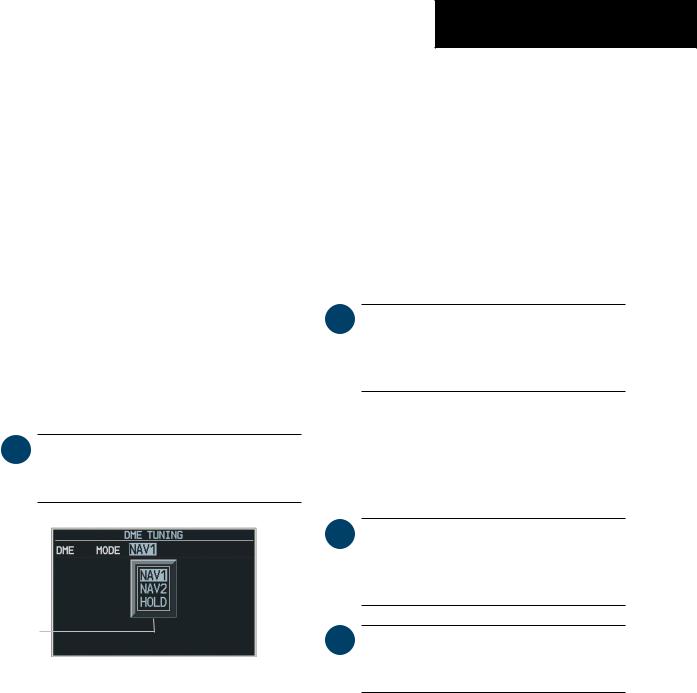
The DME radio is tuned by selecting the associated NAV system or HOLD in the DME Tuning window. The DME Tuning window is located to the right of the HSI on the lower right corner of the PFD. Pressing the top-level DME softkey toggles the DME Tuning window ON and OFF.
NOTE: When another Auxiliary window is turned on,the DMETuning window is replaced on the PFD.
DME
Modes
Figure 3-18 DME Tuning Window
NAV/COM
Selecting DME Transceiver Pairing
The following DME transceiver pairing can be selected:
•NAV1–TunestheDMEfrequencyfromtheselected NAV1 frequency.
•NAV2–TunestheDMEfrequencyfromtheselected NAV2 frequency.
•HOLD – When in the HOLD position, the DME frequency remains tuned to the last selected NAV frequency.
NOTE: When turning ON the G1000 for use, the system remembers the last frequency used for DMETuning and the NAV1, NAV2 or HOLD state prior to shutdown.
To select DME transceiver tuning:
1.Turn the small FMS knob to select the desired DME tuning.
2.Press the ENT key to complete the selection.
NOTE: Pressing the CLR key while in the process of DME tuning cancels the data entry and reverts back to the previously selected DME tuning state.
NOTE: Pressing the FMS knob activates/ deactivates the cursor in the DME Tuning window.
190-00498-00 Rev.A |
Garmin G1000 Pilot’s Guide for Cessna Nav III |
3-9 |