

- •Section 1 System Overview
- •1.1 System Description
- •1.2 Line Replaceable Units (LRU)
- •1.3 G1000 Controls
- •PFD/MFD Controls
- •Audio Panel Controls
- •1.4 Secure Digital (SD) Cards
- •1.5 System Power-up
- •1.6 System Operation
- •Normal Display Operation
- •Reversionary Display Operation
- •AHRS Operation
- •G1000 System Annunciations
- •Softkey Function
- •GPS Receiver Operation
- •1.7 Accessing G1000 Functionality
- •Menus
- •MFD Page Groups
- •MFD System Pages
- •1.8 Display Backlighting
- •Automatic Adjustment
- •Manual Adjustment
- •Section 2 Flight Instruments
- •2.1 Flight Instruments
- •Airspeed Indicator
- •Attitude Indicator
- •Altimeter
- •Vertical Speed Indicator (VSI)
- •Vertical Deviation
- •Horizontal Situation Indicator (HSI)
- •Course Deviation Indicator (CDI)
- •2.2 Supplemental Flight Data
- •Outside Air Temperature
- •Wind Data
- •Vertical Navigation (VNV) Indications
- •2.3 PFD Annunciations and Alerting Functions
- •G1000 System Alerting
- •Marker Beacon Annunciations
- •Traffic Annunciation
- •TAWS Annunciations
- •Altitude Alerting
- •Low Altitude Annunciation
- •Minimum Descent Altitude/Decision Height Alerting
- •2.4 Abnormal Operations
- •Abnormal GPS Conditions
- •Unusual Attitudes
- •Section 3 Engine Indication System (EIS)
- •3.1 Engine Display
- •3.2 Lean Display
- •Normally-aspirated Aircraft
- •Turbocharged Aircraft
- •3.3 System Display
- •Section 4 audio panel and CNS
- •4.1 Overview
- •MFD/PFD Controls and Frequency Display
- •Audio Panel Controls
- •4.2 COM Operation
- •COM Transceiver Selection and Activation
- •COM Transceiver Manual Tuning
- •Quick-Tuning and Activating 121.500 MHz
- •Auto-tuning the COM Frequency
- •Frequency Spacing
- •Automatic Squelch
- •Volume
- •4.3 NAV Operation
- •NAV Radio Selection and Activation
- •NAV Receiver Manual Tuning
- •Auto-tuning a NAV Frequency from the MFD
- •Marker Beacon Receiver
- •DME Tuning (Optional)
- •4.4 GTX 33 Mode S Transponder
- •Transponder Controls
- •Transponder Mode Selection
- •Entering a Transponder Code
- •IDENT Function
- •Flight ID Reporting
- •4.5 Additional Audio Panel Functions
- •Power-Up
- •Mono/Stereo Headsets
- •Speaker
- •Intercom
- •Passenger Address (PA) System
- •Clearance Recorder and Player
- •Entertainment Inputs
- •4.6 Audio Panel Preflight Procedure
- •4.7 Abnormal Operation
- •Stuck Microphone
- •COM Tuning Failure
- •Audio Panel Fail-Safe Operation
- •Reversionary Mode
- •Section 5 Flight Management
- •5.1 Introduction
- •Navigation Status Box
- •5.2 Using Map Displays
- •Map Orientation
- •Map Range
- •Map Panning
- •Measuring Bearing and Distance
- •Topography
- •Map Symbols
- •Airways
- •Track Vector
- •Wind Vector
- •Nav Range Ring
- •Fuel Range Ring
- •5.3 Waypoints
- •Airports
- •Intersections
- •NDBs
- •VORs
- •User Waypoints
- •5.4 Airspaces
- •5.5 Direct-to-Navigation
- •5.6 Flight Planning
- •Flight Plan Creation
- •Adding Waypoints To An Existing Flight Plan
- •Adding Airways to a Flight Plan
- •Adding Procedures To A Stored Flight Plan
- •Flight Plan Storage
- •Flight Plan Editing
- •Along Track Offsets
- •Parallel Track
- •Activating a Flight Plan Leg
- •Inverting a Flight Plan
- •Flight Plan Views
- •Closest Point of FPL
- •5.7 Vertical Navigation
- •Altitude Constraints
- •5.8 Procedures
- •Departures
- •Arrivals
- •Approaches
- •5.9 Trip Planning
- •Trip Planning
- •5.10 RAIM Prediction
- •5.11 Navigating a Flight Plan
- •5.12 Abnormal Operation
- •Section 6 Hazard Avoidance
- •6.1 XM Satellite Weather
- •Activating Services
- •Using XM Satellite Weather Products
- •6.2 WX-500 Stormscope (Optional)
- •Setting Up Stormscope on the Navigation Map
- •Selecting the Stormscope Page
- •6.3 Terrain Proximity
- •Displaying Terrain Proximity Data
- •Terrain Proximity Page
- •6.4 TAWs (Optional)
- •Displaying TAWS Data
- •TAWS Page
- •TAWS Alerts
- •System Status
- •6.5 Traffic Information Service (TIS)
- •Displaying TRAFFIC Data
- •Traffic Map Page
- •TIS Alerts
- •System Status
- •6.6 Traffic Advisory System (TAS) (Optional)
- •TAS Symbology
- •Operation
- •Altitude Display
- •Traffic Map Page Display Range
- •TAS Alerts
- •System Status
- •6.7 ADS-B Traffic (Optional)
- •Section 7 Automatic Flight Control System
- •7.2 Flight Director Operation
- •Activating the Flight Director
- •AFCS Status Box
- •Command Bars
- •Flight Director Modes
- •7.3 Vertical Modes
- •Pitch Hold Mode (PIT)
- •Selected Altitude capture Mode (ALTs)
- •Altitude hold mode (alt)
- •Vertical Speed Mode (VS)
- •Flight Level Change Mode (FLC)
- •Vertical Navigation Modes (VPTH, ALTV)
- •Glidepath Mode (GP) (waas only)
- •Glideslope Mode (GS)
- •Go Around (GA) Mode
- •7.4 Lateral Modes
- •Roll Hold Mode (ROL)
- •Heading Select Mode (HDG)
- •Navigation mode (GPS, VOR, LOC)
- •Approach mode (GPS, VAPP, LOC)
- •Backcourse Mode (BC)
- •7.5 Autopilot Operation
- •Engaging the Autopilot
- •Control Wheel Steering
- •Disengaging the Autopilot
- •7.6 Example Procedures
- •Departure
- •Intercepting a VOR Radial
- •Flying a Flight Plan/GPS Course
- •Descent
- •Approach
- •Go Around/Missed Approach
- •7.7 AFCS Annunciations and Alerts
- •AFCS Status Alerts
- •Overspeed Protection
- •Section 8 Additional Features
- •8.1 SafeTaxi
- •SafeTaxi Cycle Number and Revision
- •8.2 ChartView
- •ChartView Softkeys
- •Terminal Procedures Charts
- •Chart Options
- •Day/Night View
- •ChartView Cycle Number and Expiration Date
- •8.3 FliteCharts
- •FliteCharts Softkeys
- •Terminal Procedures Charts
- •Chart Options
- •Day/Night View
- •FliteCharts Cycle Number and Expiration Date
- •8.4 XM Radio Entertainment (Optional)
- •Activating XM Satellite Radio Services
- •Using XM Radio
- •Automatic Audio Muting
- •8.5 Scheduler
- •8.5 Abnormal Operation
- •Annunciations and Alerts
- •Alert Level Definitions
- •Nav III Aircraft Alerts
- •CO Guardian Messages
- •G1000 System Annunciations
- •Other G1000 Aural Alerts
- •G1000 System Message Advisories
- •AFCS Alerts
- •TAWS ALERTS
- •TAWS System Status Annunciations
- •SD Card Use
- •Jeppesen Databases
- •Garmin Databases
- •Glossary
- •Frequently Asked Questions
- •General TIS Information
- •Introduction
- •TIS vs. TAS/TCAS
- •TIS Limitations
- •Map Symbols
- •Index
AUTOMATIC FLIGHT CONTROL SYSTEM
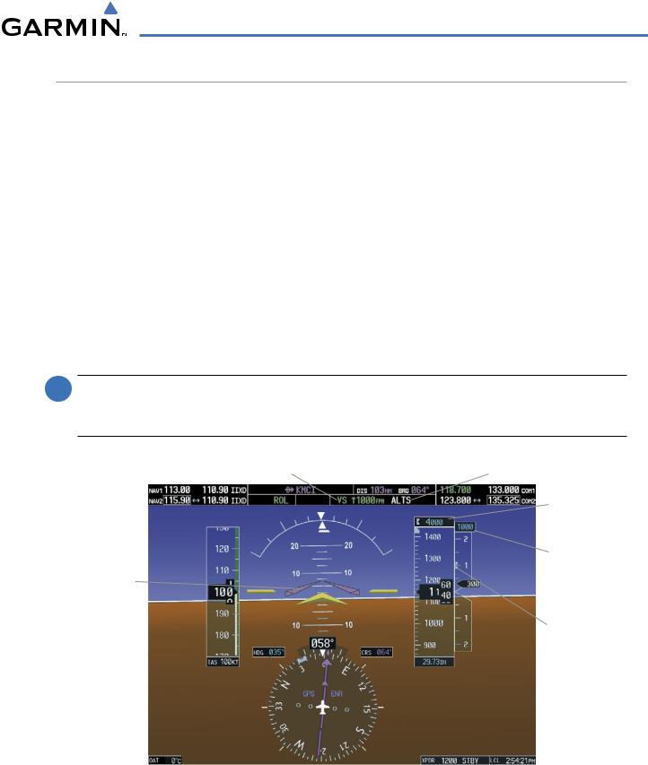
VERTICAL SPEED MODE (VS)
Vertical Speed Mode is activated by pressing the VS Key. The annunciation ‘VS’ appears in the active pitch mode field, along with the Vertical Speed Reference to the right; the Vertical Speed Reference is also displayed above or below the Vertical Speed Indicator, depending on whether the aircraft is climbing or descending.
In Vertical Speed Mode, the flight director acquires and maintains a Vertical Speed Reference as it climbs or descends to the Selected Altitude (shown above the Altimeter). Current aircraft vertical speed becomes the Vertical Speed Reference at the moment of Vertical Speed Mode engagement. A Vertical Speed Reference Bug corresponding to the Vertical Speed Reference is shown on the indicator.
CHANGING THE VERTICAL SPEED REFERENCE
The Vertical Speed Reference (shown both in the AFCS Status Box and above/below the Vertical Speed Indicator) may be changed:
•Using the NOSE UP/NOSE DN Keys
•By pressing the CWS Button, hand-flying the aircraft to a new Vertical Speed Reference, then releasing the CWS Button
 NOTE: If the Selected Altitude is reached during CWS maneuvering, the Altitude Reference is not changed. To adjust the Altitude Reference in this case, the CWS Button must be pressed again after the Selected Altitude is reached.
Vertical Speed |
Vertical Speed |
Selected Altitude |
|
Mode Active |
Reference |
Capture Mode Armed |
|
|
|
|
Selected |
|
|
|
|
|
|
|
Altitude |
|
|
|
Vertical |
Command |
|
|
Speed |
|
|
Reference |
|
Bars Indicate |
|
|
|
Climb to Attain |
|
|
|
Vertical Speed |
|
|
|
Reference |
|
|
Vertical Speed |
|
|
|
Reference |
|
|
|
Bug |
Figure 7-8 Vertical Speed Mode
190-00498-03 Rev.A |
Garmin G1000 Pilot’s Guide for Cessna Nav III |
7-11 |
AUTOMATIC FLIGHT CONTROL SYSTEM
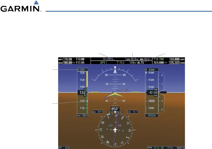
FLIGHT LEVEL CHANGE MODE (FLC)
 NOTE: The Selected Altitude should be set before engaging Flight Level Change Mode.
Flight Level Change Mode is selected by pressing the FLC Key. This mode acquires and maintains the Airspeed Reference while climbing or descending to the Selected Altitude (shown above the Altimeter). When Flight Level Change Mode is active, the flight director continuously monitors Selected Altitude, airspeed, and altitude.
The Airspeed Reference is set to the current airspeed upon mode activation. Flight Level Change Mode is indicated by an ‘FLC’ annunciation beside the Airspeed Reference in the AFCS Status Box. The Airspeed Reference is also displayed directly above the Airspeed Indicator, along with a bug corresponding to the Airspeed Reference along the tape.
Engine power must be adjusted to allow the autopilot to fly the aircraft at a pitch attitude corresponding to the desired flight profile (climb or descent) while maintaining the Airspeed Reference. The flight director maintains the current altitude until either engine power or the Airspeed Reference are adjusted and does not allow the aircraft to climb or descend away from the Selected Altitude.
CHANGING THE AIRSPEED REFERENCE
The Airspeed Reference (shown in both the AFCS Status Box and above the Airspeed Indicator) may be adjusted by:
•Using the NOSE UP/NOSE DN Keys
•Pressing the CWS Button, hand-flying the aircraft to a new airspeed, then releasing the CWS Button to establish the new Airspeed Reference
 NOTE: If the Selected Altitude is reached during CWS maneuvering, the Altitude Reference is not changed. To adjust the Altitude Reference in this case, the CWS Button must be pressed again after the Selected Altitude is reached.
7-12 |
Garmin G1000 Pilot’s Guide for Cessna Nav III |
190-00498-03 Rev.A |
AUTOMATIC FLIGHT CONTROL SYSTEM
Flight Level Change |
Airspeed |
Selected Altitude |
Mode Active |
Reference |
Capture Mode Armed |
Airspeed
Reference
Airspeed
Reference
Bug
Figure 7-9 Flight Level Change Mode
190-00498-03 Rev.A |
Garmin G1000 Pilot’s Guide for Cessna Nav III |
7-13 |
AUTOMATIC FLIGHT CONTROL SYSTEM
VERTICAL NAVIGATION MODES (VPTH, ALTV)
 NOTE: VNV is disabled when parallel track is active.
 NOTE: The Selected Altitude takes precedence over any other vertical constraints.
Vertical Navigation (VNV) flight control is available for enroute/terminal cruise and descent operations any time that VNV flight planning is available. Refer to the Flight Management Section for more information on VNV flight plans. Conditions for availability include, but are not limited to:
•The selected navigation source is GPS.
•A VNV flight plan (with at least one altitude-constrained waypoint) or vertical direct-to is active.
•VNV is enabled (VNV ENBL Softkey pressed on the MFD).
•Crosstrack error is valid and within certain limits.
•Desired/actual track are valid or track angle error is within certain limits.
•The VNV Target Altitude of the active waypoint is no more than 250 ft above the current aircraft altitude.
The flight director may be armed for VNV at any time, but no target altitudes are captured during a climb. The Command Bars provide vertical profile guidance based on specified altitudes (entered manually or loaded from the database) at waypoints in the active flight plan or vertical direct-to. The appropriate VNV flight control modes are sequenced by the flight director to follow the path defined by the vertical profile. Upon reaching the last waypoint in the VNV flight plan, the flight director transitions to Altitude Hold Mode and cancels any armed VNV modes.
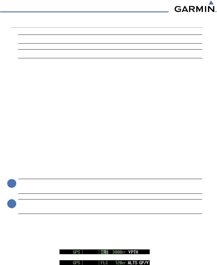
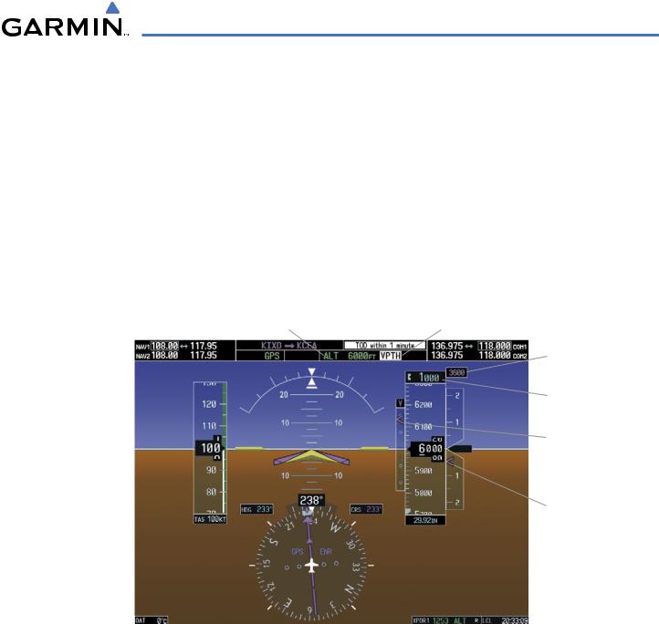
VERTICAL PATH TRACKING MODE (VPTH)
 NOTE: If another pitch mode key is pressed while Vertical Path Tracking Mode is selected, Vertical Path Tracking Mode reverts to armed.
 NOTE: Pressing the CWS Button while Vertical Path Tracking Mode is active does not cancel the mode. The autopilot guides the aircraft back to the descent path upon release of the CWS Button.
When a vertical profile (VNV flight plan) is active and the VNV Key is pressed, Vertical Path Tracking Mode is armed in preparation for descent path capture. ‘VPTH’ (or ‘/V’ when Glidepath or Glideslope Mode is concurrently armed) is annunciated in white in addition to previously armed modes. If applicable, the appropriate altitude capture mode is armed for capture of the next VNV Target Altitude (ALTV) or the Selected Altitude (ALTS), whichever is greater.
Figure 7-10 Vertical Path Tracking Armed Annunciations
7-14 |
Garmin G1000 Pilot’s Guide for Cessna Nav III |
190-00498-03 Rev.A |
AUTOMATIC FLIGHT CONTROL SYSTEM
Prior to descent path interception, the Selected Altitude must be set below the current aircraft altitude by at least 75 feet. For the flight director to transition from Altitude Hold to Vertical Path Tracking Mode, acknowledgment is required within 5 minutes of descent path interception by:
• Pressing the VNV Key |
• Adjusting the Selected Altitude |
If acknowledgment is not received within 1 minute of descent path interception, the white ‘VPTH’ annunciation starts to flash. Flashing continues until acknowledged or the descent path is intercepted. If the descent is not confirmed by the time of interception, Vertical Path Tracking Mode remains armed and the descent is not captured.
In conjunction with the “TOD [top of descent] within 1 minute” annunciation in the Navigation Status Box and the “Vertical track” voice message, VNV indications (VNV Target Altitude, vertical deviation, and vertical speed required) appear on the PFD in magenta (Figure 7-11).
|
|
|
Vertical Path Tracking |
|
|
Altitude Hold |
Armed, (Flashing Indicates |
||
|
Mode Active |
Acknowledgment Required) |
||
|
|
|
VNV Target |
|
|
|
|
|
Altitude |
|
|
|
|
Selected |
|
|
|
|
Altitude Below |
|
|
|
|
VNV Target |
|
|
|
|
Vertical |
|
|
|
|
Deviation |
|
|
|
|
Indicator |
|
|
|
|
Required |
|
|
|
|
Vertical |
|
|
|
Speed Bug |
|
GPS is |
|
Enroute |
||
Selected |
|
|
|
Phase |
|
|
|||
Navigation |
of Flight |
|||
Source |
|
|
||
Figure 7-11 Vertical Path Capture
190-00498-03 Rev.A |
Garmin G1000 Pilot’s Guide for Cessna Nav III |
7-15 |
AUTOMATIC FLIGHT CONTROL SYSTEM
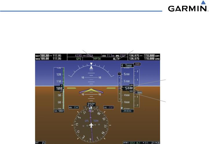
When a descent leg is captured (i.e., vertical deviation becomes valid), Vertical Path Tracking becomes active and tracks the descent profile (Figure 7-12). An altitude capture mode (‘ALTS’ or ‘ALTV’) is armed as appropriate.
|
Vertical Path |
VNV Target Altitude |
|||
|
Tracking Active |
Capture Armed |
|||
|
|
|
|
VNV Target |
|
|
|
|
|
|
Altitude |
|
|
|
|
|
Vertical |
|
|
|
|
|
Deviation |
|
|
|
|
|
Indicator |
|
|
|
|
Required |
|
|
|
|
|
|
Vertical |
|
|
|
|
|
Speed |
|
|
|
|
Indication |
|
GPS is |
|
|
Terminal |
||
Selected |
|
|
|
|
|
|
|
|
|
Phase of |
|
Navigation |
|
|
|||
|
|
Flight |
|||
Source |
|
|
|||
|
|
|
|||
Figure 7-12 Vertical Path Tracking Mode
If the Altimeter’s barometric setting is adjusted while Vertical Path Tracking is active, the flight director increases/decreases the descent rate by up to 500 fpm to re-establish the aircraft on the descent path (without commanding a climb). Adjusting the altimeter barometric setting creates discontinuities in VNV vertical deviation, moving the descent path. For large adjustments, it may take several minutes for the aircraft to reestablish on the descent path. If the change is made while nearing a waypoint with a VNV Target Altitude, the aircraft may not re-establish on the descent path in time to meet the vertical constraint.
7-16 |
Garmin G1000 Pilot’s Guide for Cessna Nav III |
190-00498-03 Rev.A |
AUTOMATIC FLIGHT CONTROL SYSTEM
AUTOMATIC REVERSION TO PITCH HOLD MODE
Several situations can occur while Vertical Path Tracking Mode is active which cause the flight director to revert to Pitch Hold Mode:
•Vertical deviation exceeds 200 feet during an overspeed condition.
•Vertical deviation experiences a discontinuity that both exceeds 200 feet in magnitude and results in the vertical deviation exceeding 200 feet in magnitude. Such discontinuities are usually caused by flight plan changes that affect the vertical profile.
•Vertical deviation becomes invalid (the Vertical Deviation Indicator is removed from the PFD).
•A display enters Reversionary Mode (this does not apply to an active vertical direct-to).
Unless VNV is disabled, Vertical Path Tracking Mode and the appropriate altitude capture mode become armed following the reversion to Pitch Hold Mode to allow for possible profile recapture.
NON-PATH DESCENTS
Pitch Hold, Vertical Speed, and Flight Level Change modes can also be used to fly non-path descents while VNV flight control is selected. If the VS or FLC Key is pressed while Vertical Path Tracking Mode is selected, Vertical Path Tracking Mode reverts to armed along with the appropriate altitude capture mode to allow profile re-capture.
Figure 7-13 Flight Level Change VNV Non-Path Descent
To prevent immediate profile re-capture, the following must be satisfied:
•At least 10 seconds have passed since the non-path transition was initiated
•Vertical deviation from the profile has exceeded 250 feet, but is now less than 200 feet Pressing the VNV Key twice re-arms Vertical Path Tracking for immediate profile re-capture.
190-00498-03 Rev.A |
Garmin G1000 Pilot’s Guide for Cessna Nav III |
7-17 |
AUTOMATIC FLIGHT CONTROL SYSTEM
VNV TARGET ALTITUDE CAPTURE MODE (ALTV)
 NOTE: Armed VNV Target Altitude and Selected Altitude capture modes are mutually exclusive. However, SelectedAltitude Capture Mode is armed implicitly (not annunciated) wheneverVNVTargetAltitude Capture Mode is armed.
VNV Target Altitude Capture is analogous to Selected Altitude Capture Mode and is armed automatically after the VNV Key is pressed and the next VNV Target Altitude is to be intercepted before the Selected Altitude. The annunciation ‘ALTV’ indicates that the VNV Target Altitude is to be captured. VNV Target Altitudes are shown in the active flight plan or vertical direct-to, and can be entered manually or loaded from a database (see the Flight Management Section for details). At the same time as “TOD within 1 minute” is annunciated in the Navigation Status Box, the active VNV Target Altitude is displayed above the Vertical Speed Indicator (see Figure 7-11).
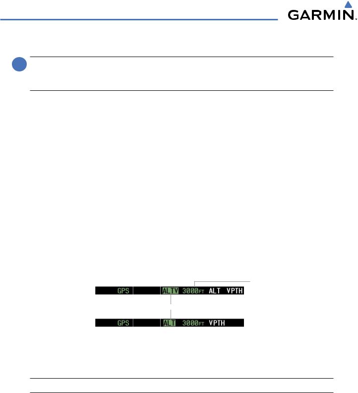
As the aircraft nears the VNV Target Altitude, the flight director automatically transitions to VNV Target Altitude Capture Mode with Altitude Hold Mode armed. This automatic transition is indicated by the green ‘ALTV’ annunciation flashing for up to 10 seconds and the appearance of the white ‘ALT” annunciation. The VNV Target Altitude is shown as the Altitude Reference beside the ‘ALTV’ annunciation and remains displayed above the Vertical Speed Indicator. The Required Vertical Speed Indication (RSVI) is removed once VNV Target Altitude Capture Mode becomes active.
At 50 feet from the VNV Target Altitude, the flight director automatically transitions from VNV Target Altitude Capture to Altitude Hold Mode and tracks the level leg. As Altitude Hold Mode becomes active, the white ‘ALT’ annunciation moves to the active vertical mode field and flashes green for 10 seconds to indicate the automatic transition. The flight director automatically arms Vertical Path Tracking, allowing upcoming descent legs to be captured and subsequently tracked.
Altitude Reference
(In This Case, Equal
To VNV Altitude
Target)
Flash up to 10 sec, Indicating Automatic Transition
Figure 7-14 Automatic Mode Transitions During Altitude Capture
CHANGING THE VNV TARGET ALTITUDE
 NOTE: Pressing the CWS Button while in VNV Target Altitude Capture Mode does not cancel the mode.
Changing the current VNV Target Altitude while VNV Target Altitude Capture Mode is active causes the flight director to revert to Pitch Hold Mode. Vertical Path Tracking and the appropriate altitude capture mode are armed in preparation to capture the new VNV Target Altitude or the Selected Altitude, depending on which altitude is to be intercepted first.
VNV target altitudes can be changed while editing the active flight plan (see the Flight Management Section for details).
7-18 |
Garmin G1000 Pilot’s Guide for Cessna Nav III |
190-00498-03 Rev.A |