- •Section 1 System Overview
- •1.1 System Description
- •1.2 Line Replaceable Units (LRU)
- •1.3 G1000 Controls
- •PFD/MFD Controls
- •Audio Panel Controls
- •1.4 Secure Digital (SD) Cards
- •1.5 System Power-up
- •1.6 System Operation
- •Normal Display Operation
- •Reversionary Display Operation
- •AHRS Operation
- •G1000 System Annunciations
- •Softkey Function
- •GPS Receiver Operation
- •1.7 Accessing G1000 Functionality
- •Menus
- •MFD Page Groups
- •MFD System Pages
- •1.8 Display Backlighting
- •Automatic Adjustment
- •Manual Adjustment
- •Section 2 Flight Instruments
- •2.1 Flight Instruments
- •Airspeed Indicator
- •Attitude Indicator
- •Altimeter
- •Vertical Speed Indicator (VSI)
- •Vertical Deviation
- •Horizontal Situation Indicator (HSI)
- •Course Deviation Indicator (CDI)
- •2.2 Supplemental Flight Data
- •Outside Air Temperature
- •Wind Data
- •Vertical Navigation (VNV) Indications
- •2.3 PFD Annunciations and Alerting Functions
- •G1000 System Alerting
- •Marker Beacon Annunciations
- •Traffic Annunciation
- •TAWS Annunciations
- •Altitude Alerting
- •Low Altitude Annunciation
- •Minimum Descent Altitude/Decision Height Alerting
- •2.4 Abnormal Operations
- •Abnormal GPS Conditions
- •Unusual Attitudes
- •Section 3 Engine Indication System (EIS)
- •3.1 Engine Display
- •3.2 Lean Display
- •Normally-aspirated Aircraft
- •Turbocharged Aircraft
- •3.3 System Display
- •Section 4 audio panel and CNS
- •4.1 Overview
- •MFD/PFD Controls and Frequency Display
- •Audio Panel Controls
- •4.2 COM Operation
- •COM Transceiver Selection and Activation
- •COM Transceiver Manual Tuning
- •Quick-Tuning and Activating 121.500 MHz
- •Auto-tuning the COM Frequency
- •Frequency Spacing
- •Automatic Squelch
- •Volume
- •4.3 NAV Operation
- •NAV Radio Selection and Activation
- •NAV Receiver Manual Tuning
- •Auto-tuning a NAV Frequency from the MFD
- •Marker Beacon Receiver
- •DME Tuning (Optional)
- •4.4 GTX 33 Mode S Transponder
- •Transponder Controls
- •Transponder Mode Selection
- •Entering a Transponder Code
- •IDENT Function
- •Flight ID Reporting
- •4.5 Additional Audio Panel Functions
- •Power-Up
- •Mono/Stereo Headsets
- •Speaker
- •Intercom
- •Passenger Address (PA) System
- •Clearance Recorder and Player
- •Entertainment Inputs
- •4.6 Audio Panel Preflight Procedure
- •4.7 Abnormal Operation
- •Stuck Microphone
- •COM Tuning Failure
- •Audio Panel Fail-Safe Operation
- •Reversionary Mode
- •Section 5 Flight Management
- •5.1 Introduction
- •Navigation Status Box
- •5.2 Using Map Displays
- •Map Orientation
- •Map Range
- •Map Panning
- •Measuring Bearing and Distance
- •Topography
- •Map Symbols
- •Airways
- •Track Vector
- •Wind Vector
- •Nav Range Ring
- •Fuel Range Ring
- •5.3 Waypoints
- •Airports
- •Intersections
- •NDBs
- •VORs
- •User Waypoints
- •5.4 Airspaces
- •5.5 Direct-to-Navigation
- •5.6 Flight Planning
- •Flight Plan Creation
- •Adding Waypoints To An Existing Flight Plan
- •Adding Airways to a Flight Plan
- •Adding Procedures To A Stored Flight Plan
- •Flight Plan Storage
- •Flight Plan Editing
- •Along Track Offsets
- •Parallel Track
- •Activating a Flight Plan Leg
- •Inverting a Flight Plan
- •Flight Plan Views
- •Closest Point of FPL
- •5.7 Vertical Navigation
- •Altitude Constraints
- •5.8 Procedures
- •Departures
- •Arrivals
- •Approaches
- •5.9 Trip Planning
- •Trip Planning
- •5.10 RAIM Prediction
- •5.11 Navigating a Flight Plan
- •5.12 Abnormal Operation
- •Section 6 Hazard Avoidance
- •6.1 XM Satellite Weather
- •Activating Services
- •Using XM Satellite Weather Products
- •6.2 WX-500 Stormscope (Optional)
- •Setting Up Stormscope on the Navigation Map
- •Selecting the Stormscope Page
- •6.3 Terrain Proximity
- •Displaying Terrain Proximity Data
- •Terrain Proximity Page
- •6.4 TAWs (Optional)
- •Displaying TAWS Data
- •TAWS Page
- •TAWS Alerts
- •System Status
- •6.5 Traffic Information Service (TIS)
- •Displaying TRAFFIC Data
- •Traffic Map Page
- •TIS Alerts
- •System Status
- •6.6 Traffic Advisory System (TAS) (Optional)
- •TAS Symbology
- •Operation
- •Altitude Display
- •Traffic Map Page Display Range
- •TAS Alerts
- •System Status
- •6.7 ADS-B Traffic (Optional)
- •Section 7 Automatic Flight Control System
- •7.2 Flight Director Operation
- •Activating the Flight Director
- •AFCS Status Box
- •Command Bars
- •Flight Director Modes
- •7.3 Vertical Modes
- •Pitch Hold Mode (PIT)
- •Selected Altitude capture Mode (ALTs)
- •Altitude hold mode (alt)
- •Vertical Speed Mode (VS)
- •Flight Level Change Mode (FLC)
- •Vertical Navigation Modes (VPTH, ALTV)
- •Glidepath Mode (GP) (waas only)
- •Glideslope Mode (GS)
- •Go Around (GA) Mode
- •7.4 Lateral Modes
- •Roll Hold Mode (ROL)
- •Heading Select Mode (HDG)
- •Navigation mode (GPS, VOR, LOC)
- •Approach mode (GPS, VAPP, LOC)
- •Backcourse Mode (BC)
- •7.5 Autopilot Operation
- •Engaging the Autopilot
- •Control Wheel Steering
- •Disengaging the Autopilot
- •7.6 Example Procedures
- •Departure
- •Intercepting a VOR Radial
- •Flying a Flight Plan/GPS Course
- •Descent
- •Approach
- •Go Around/Missed Approach
- •7.7 AFCS Annunciations and Alerts
- •AFCS Status Alerts
- •Overspeed Protection
- •Section 8 Additional Features
- •8.1 SafeTaxi
- •SafeTaxi Cycle Number and Revision
- •8.2 ChartView
- •ChartView Softkeys
- •Terminal Procedures Charts
- •Chart Options
- •Day/Night View
- •ChartView Cycle Number and Expiration Date
- •8.3 FliteCharts
- •FliteCharts Softkeys
- •Terminal Procedures Charts
- •Chart Options
- •Day/Night View
- •FliteCharts Cycle Number and Expiration Date
- •8.4 XM Radio Entertainment (Optional)
- •Activating XM Satellite Radio Services
- •Using XM Radio
- •Automatic Audio Muting
- •8.5 Scheduler
- •8.5 Abnormal Operation
- •Annunciations and Alerts
- •Alert Level Definitions
- •Nav III Aircraft Alerts
- •CO Guardian Messages
- •G1000 System Annunciations
- •Other G1000 Aural Alerts
- •G1000 System Message Advisories
- •AFCS Alerts
- •TAWS ALERTS
- •TAWS System Status Annunciations
- •SD Card Use
- •Jeppesen Databases
- •Garmin Databases
- •Glossary
- •Frequently Asked Questions
- •General TIS Information
- •Introduction
- •TIS vs. TAS/TCAS
- •TIS Limitations
- •Map Symbols
- •Index
ENGINE INDICATION SYSTEM
3.3 SYSTEM DISPLAY
NOTE: Fuel calculations do not use the aircraft fuel quantity indicators and are calculated from the last time the fuel was reset.
NOTE: The pilot should refer to the Pilot’s Operating Handbook (POH) for fuel values and limitations. The displayed fuel remaining can be adjusted up to 53 gal (Models 172R, 172S) or 87 gal (Models 182T,T182T, 206H,T206H).
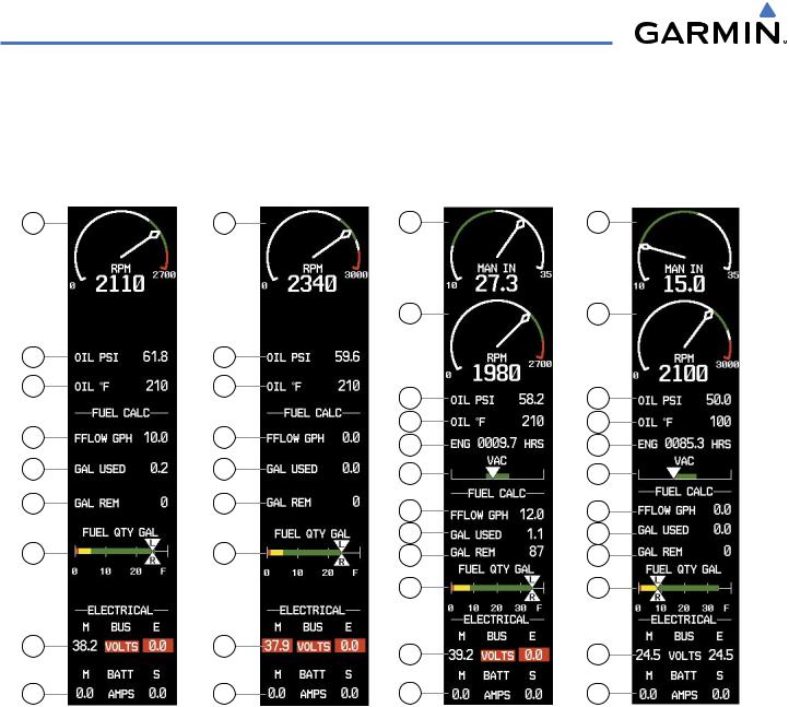
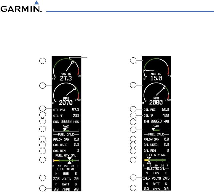
The System Display is accessed by pressing the ENGINE Softkey followed by the SYSTEM Softkey and shows critical engine, fuel, and electrical parameters. The engine gauge(s) and Fuel Quantity Indicator remain on the System Display. Numeric readouts for oil pressure and temperature are displayed, and for Models 182T, T182T, 206H, and T206H, a readout for engine hours and the Vacuum Pressure Indicator are also shown. Electrical indicators are at the bottom of the display.
Fuel calculations are also shown on this on this display. Fuel calculations are based on the fuel flow totalizer and the displayed fuel remaining, adjusted by the pilot using the following softkeys:
•RST FUEL – Resets totalizer-based fuel remaining (GAL REM) and the fuel used (GAL USED) to zero
•GAL REM – Gives access to softkeys for adjusting the amount of fuel remaining for purposes of fuel calculations
Fuel remaining can be adjusted using the appropriate softkeys in one or ten-gallon increments, up to either the maximum amount allowed for the aircraft or to the tab amount: 35 gallons (Models 172R and 172S) or 64 gallons (Models 182T, T182T, 206H, and T206H).
3-10 |
Garmin G1000 Pilot’s Guide for Cessna Nav III |
190-00498-03 Rev.A |
ENGINE INDICATION SYSTEM
1 Engine Manifold Pressure Gauge
(MAN IN)
Models 182T, T182T, 206H, T206H
2 Tachometer
(RPM)
3 Oil Pressure
(OIL PSI)
4 Oil Temperature
(OIL °F)
Displays engine power in inches of mercury (in Hg)
Turbocharged aircraft – Red range indicates maximum manifold pressure
Model T182T – A white tick mark indicates the cruise manifold pressure
Displays propeller speeds in revolutions per minute (rpm) Red range indicates propeller overspeed warning
Models172S,206H,andT206H–White high-rpmrangeindicates above normal operating speeds
Displays pressure of the oil supplied to the engine in pounds per square inch (psi)
Displays the engine oil temperature in degrees Fahrenheit (°F)
5 |
Engine Hours (Tach) |
Displays a numeric readout for the time in hours (hrs) the engine has |
|
(ENG HRS) |
been in service |
|
Models 182T, T182T, 206H, T206H |
|
6 |
Vacuum Pressure Indicator |
Displays vacuum pump pressure for the standby instruments |
|
(VAC) |
|
|
Models 182T, T182T, 206H, T206H |
|
7 |
Fuel Flow |
Displays the current fuel flow in gallons per hour (gph) |
|
(FFLOW GPH) |
|
8 |
Calculated Fuel Used |
Displays quantity of fuel used in gallons (gal) based on fuel flow since |
|
(GAL USED) |
last reset |
9 |
Set Fuel Remaining |
Displays current fuel remaining in gal as set by the pilot and adjusted |
|
(GAL REM) |
for fuel burn since last set |
10 |
Fuel Quantity Indicator |
Displays the quantity of fuel in gal in each tank (left–L and right–R) |
|
(FUEL QTY GAL) |
from zero to full (F) |
|
|
When full, the indicator displays to 35 gal per side (26 gal for Models |
|
|
172R and 172S). |
11 |
Voltmeter |
Displays the main and essential bus voltages |
|
(M, E BUS VOLTS) |
|
12 |
Ammeter |
Displays the main and standby battery load in amperes |
|
(M, S BATT AMPS) |
|
190-00498-03 Rev.A |
Garmin G1000 Pilot’s Guide for Cessna Nav III |
3-11 |
ENGINE INDICATION SYSTEM
2 |
2 |
1 |
1 |
|
|
2 |
2 |
|
3 |
3 |
|
|
|
4 |
4 |
3 |
3 |
|
|
|
|||
7 |
7 |
4 |
4 |
|
5 |
5 |
|||
|
|
|||
8 |
8 |
6 |
6 |
|
|
|
|||
9 |
9 |
7 |
7 |
|
|
|
|||
|
|
8 |
8 |
|
10 |
10 |
9 |
9 |
|
|
|
10 |
10 |
|
11 |
11 |
11 |
11 |
|
|
|
|||
12 |
12 |
12 |
12 |
|
Model 172R |
Model 172S |
Model 182T |
Model 206H |
|
|
Figure 3-8 System Display (Normally-aspirated Aircraft) |
|
3-12 |
Garmin G1000 Pilot’s Guide for Cessna Nav III |
190-00498-03 Rev.A |
ENGINE INDICATION SYSTEM
1
2
3
4
5
6
7
8
9
10
11
12
Cruise |
1 |
|
Manifold |
||
|
||
Pressure |
|
|
|
2 |
3
4
5
6
7
8
9
10
11
12
Model T182T |
Model T206H |
Figure 3-9 System Display (Turbocharged Aircraft)
190-00498-03 Rev.A |
Garmin G1000 Pilot’s Guide for Cessna Nav III |
3-13 |
ENGINE INDICATION SYSTEM
BLANK PAGE
3-14 |
Garmin G1000 Pilot’s Guide for Cessna Nav III |
190-00498-03 Rev.A |