

- •Section 1 System Overview
- •1.1 System Description
- •1.2 Line Replaceable Units (LRU)
- •1.3 G1000 Controls
- •PFD/MFD Controls
- •Audio Panel Controls
- •1.4 Secure Digital (SD) Cards
- •1.5 System Power-up
- •1.6 System Operation
- •Normal Display Operation
- •Reversionary Display Operation
- •AHRS Operation
- •G1000 System Annunciations
- •Softkey Function
- •GPS Receiver Operation
- •1.7 Accessing G1000 Functionality
- •Menus
- •MFD Page Groups
- •MFD System Pages
- •1.8 Display Backlighting
- •Automatic Adjustment
- •Manual Adjustment
- •Section 2 Flight Instruments
- •2.1 Flight Instruments
- •Airspeed Indicator
- •Attitude Indicator
- •Altimeter
- •Vertical Speed Indicator (VSI)
- •Vertical Deviation
- •Horizontal Situation Indicator (HSI)
- •Course Deviation Indicator (CDI)
- •2.2 Supplemental Flight Data
- •Outside Air Temperature
- •Wind Data
- •Vertical Navigation (VNV) Indications
- •2.3 PFD Annunciations and Alerting Functions
- •G1000 System Alerting
- •Marker Beacon Annunciations
- •Traffic Annunciation
- •TAWS Annunciations
- •Altitude Alerting
- •Low Altitude Annunciation
- •Minimum Descent Altitude/Decision Height Alerting
- •2.4 Abnormal Operations
- •Abnormal GPS Conditions
- •Unusual Attitudes
- •Section 3 Engine Indication System (EIS)
- •3.1 Engine Display
- •3.2 Lean Display
- •Normally-aspirated Aircraft
- •Turbocharged Aircraft
- •3.3 System Display
- •Section 4 audio panel and CNS
- •4.1 Overview
- •MFD/PFD Controls and Frequency Display
- •Audio Panel Controls
- •4.2 COM Operation
- •COM Transceiver Selection and Activation
- •COM Transceiver Manual Tuning
- •Quick-Tuning and Activating 121.500 MHz
- •Auto-tuning the COM Frequency
- •Frequency Spacing
- •Automatic Squelch
- •Volume
- •4.3 NAV Operation
- •NAV Radio Selection and Activation
- •NAV Receiver Manual Tuning
- •Auto-tuning a NAV Frequency from the MFD
- •Marker Beacon Receiver
- •DME Tuning (Optional)
- •4.4 GTX 33 Mode S Transponder
- •Transponder Controls
- •Transponder Mode Selection
- •Entering a Transponder Code
- •IDENT Function
- •Flight ID Reporting
- •4.5 Additional Audio Panel Functions
- •Power-Up
- •Mono/Stereo Headsets
- •Speaker
- •Intercom
- •Passenger Address (PA) System
- •Clearance Recorder and Player
- •Entertainment Inputs
- •4.6 Audio Panel Preflight Procedure
- •4.7 Abnormal Operation
- •Stuck Microphone
- •COM Tuning Failure
- •Audio Panel Fail-Safe Operation
- •Reversionary Mode
- •Section 5 Flight Management
- •5.1 Introduction
- •Navigation Status Box
- •5.2 Using Map Displays
- •Map Orientation
- •Map Range
- •Map Panning
- •Measuring Bearing and Distance
- •Topography
- •Map Symbols
- •Airways
- •Track Vector
- •Wind Vector
- •Nav Range Ring
- •Fuel Range Ring
- •5.3 Waypoints
- •Airports
- •Intersections
- •NDBs
- •VORs
- •User Waypoints
- •5.4 Airspaces
- •5.5 Direct-to-Navigation
- •5.6 Flight Planning
- •Flight Plan Creation
- •Adding Waypoints To An Existing Flight Plan
- •Adding Airways to a Flight Plan
- •Adding Procedures To A Stored Flight Plan
- •Flight Plan Storage
- •Flight Plan Editing
- •Along Track Offsets
- •Parallel Track
- •Activating a Flight Plan Leg
- •Inverting a Flight Plan
- •Flight Plan Views
- •Closest Point of FPL
- •5.7 Vertical Navigation
- •Altitude Constraints
- •5.8 Procedures
- •Departures
- •Arrivals
- •Approaches
- •5.9 Trip Planning
- •Trip Planning
- •5.10 RAIM Prediction
- •5.11 Navigating a Flight Plan
- •5.12 Abnormal Operation
- •Section 6 Hazard Avoidance
- •6.1 XM Satellite Weather
- •Activating Services
- •Using XM Satellite Weather Products
- •6.2 WX-500 Stormscope (Optional)
- •Setting Up Stormscope on the Navigation Map
- •Selecting the Stormscope Page
- •6.3 Terrain Proximity
- •Displaying Terrain Proximity Data
- •Terrain Proximity Page
- •6.4 TAWs (Optional)
- •Displaying TAWS Data
- •TAWS Page
- •TAWS Alerts
- •System Status
- •6.5 Traffic Information Service (TIS)
- •Displaying TRAFFIC Data
- •Traffic Map Page
- •TIS Alerts
- •System Status
- •6.6 Traffic Advisory System (TAS) (Optional)
- •TAS Symbology
- •Operation
- •Altitude Display
- •Traffic Map Page Display Range
- •TAS Alerts
- •System Status
- •6.7 ADS-B Traffic (Optional)
- •Section 7 Automatic Flight Control System
- •7.2 Flight Director Operation
- •Activating the Flight Director
- •AFCS Status Box
- •Command Bars
- •Flight Director Modes
- •7.3 Vertical Modes
- •Pitch Hold Mode (PIT)
- •Selected Altitude capture Mode (ALTs)
- •Altitude hold mode (alt)
- •Vertical Speed Mode (VS)
- •Flight Level Change Mode (FLC)
- •Vertical Navigation Modes (VPTH, ALTV)
- •Glidepath Mode (GP) (waas only)
- •Glideslope Mode (GS)
- •Go Around (GA) Mode
- •7.4 Lateral Modes
- •Roll Hold Mode (ROL)
- •Heading Select Mode (HDG)
- •Navigation mode (GPS, VOR, LOC)
- •Approach mode (GPS, VAPP, LOC)
- •Backcourse Mode (BC)
- •7.5 Autopilot Operation
- •Engaging the Autopilot
- •Control Wheel Steering
- •Disengaging the Autopilot
- •7.6 Example Procedures
- •Departure
- •Intercepting a VOR Radial
- •Flying a Flight Plan/GPS Course
- •Descent
- •Approach
- •Go Around/Missed Approach
- •7.7 AFCS Annunciations and Alerts
- •AFCS Status Alerts
- •Overspeed Protection
- •Section 8 Additional Features
- •8.1 SafeTaxi
- •SafeTaxi Cycle Number and Revision
- •8.2 ChartView
- •ChartView Softkeys
- •Terminal Procedures Charts
- •Chart Options
- •Day/Night View
- •ChartView Cycle Number and Expiration Date
- •8.3 FliteCharts
- •FliteCharts Softkeys
- •Terminal Procedures Charts
- •Chart Options
- •Day/Night View
- •FliteCharts Cycle Number and Expiration Date
- •8.4 XM Radio Entertainment (Optional)
- •Activating XM Satellite Radio Services
- •Using XM Radio
- •Automatic Audio Muting
- •8.5 Scheduler
- •8.5 Abnormal Operation
- •Annunciations and Alerts
- •Alert Level Definitions
- •Nav III Aircraft Alerts
- •CO Guardian Messages
- •G1000 System Annunciations
- •Other G1000 Aural Alerts
- •G1000 System Message Advisories
- •AFCS Alerts
- •TAWS ALERTS
- •TAWS System Status Annunciations
- •SD Card Use
- •Jeppesen Databases
- •Garmin Databases
- •Glossary
- •Frequently Asked Questions
- •General TIS Information
- •Introduction
- •TIS vs. TAS/TCAS
- •TIS Limitations
- •Map Symbols
- •Index
AUTOMATIC FLIGHT CONTROL SYSTEM
7.2 FLIGHT DIRECTOR OPERATION
The flight director function provides pitch and roll commands to the AFCS and displays them on the PFD. With the flight director activated, the aircraft can be hand-flown to follow the path shown by the Command Bars. Maximum commanded pitch (+20°/-15°) and roll (22°) angles, vertical acceleration, and roll rate are limited to values established during AFCS certification. The flight director also provides commands to the autopilot.
ACTIVATING THE FLIGHT DIRECTOR
An initial press of a key listed in Table 7-1 (when the flight director is not active) activates the flight director in the listed modes. The flight director may be turned off and the Command Bars removed from the display by pressing the FD Key again. The FD Key is disabled when the autopilot is engaged.
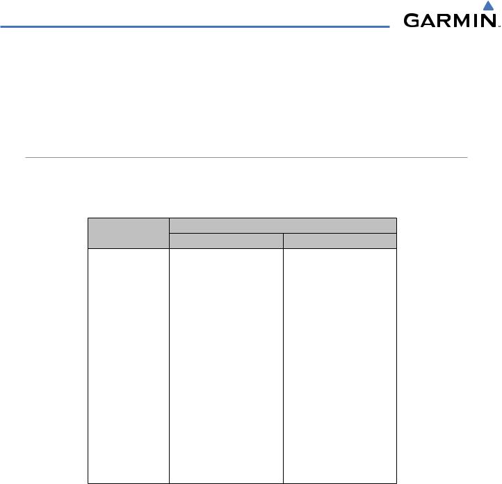
Control Pressed
Modes Selected
Lateral Vertical
FD Key |
Roll Hold (default) |
ROL |
Pitch Hold (default) |
PIT |
|
AP Key |
Roll Hold (default) |
ROL |
Pitch Hold (default) |
PIT |
|
CWS Button |
Roll Hold (default) |
ROL |
Pitch Hold (default) |
PIT |
|
GA Switch |
Takeoff (on ground) |
TO |
Takeoff (on ground) |
TO |
|
Go Around (in air) |
GA |
Go Around (in air) |
GA |
||
|
|||||
ALT Key |
Roll Hold (default) |
ROL |
Altitude Hold |
ALT |
|
VS Key |
Roll Hold (default) |
ROL |
Vertical Speed |
VS |
|
VNV Key |
Roll Hold (default) |
ROL |
Vertical Path Tracking* |
VPTH |
|
|
|
GPS |
|
|
|
NAV Key |
Navigation** |
VOR |
Pitch Hold (default) |
PIT |
|
|
|
LOC |
|
|
|
BC Key |
Backcourse*** |
BC |
Pitch Hold (default) |
PIT |
|
|
|
GPS |
|
|
|
APR Key |
Approach** |
VOR |
Pitch Hold (default) |
PIT |
|
|
|
LOC |
|
|
|
HDG Key |
Heading Select |
HDG |
Pitch Hold (default) |
PIT |
*Valid VNV flight plan must be entered before VNV Key press activates flight director.
**The selected navigation receiver must have a valid VOR or LOC signal or active GPS course before NAV or APR Key press activates flight director.
***The selected navigation receiver must have a valid LOC signal before BC Key press activates flight director.
Table 7-1 Flight Director Activation
7-4 |
Garmin G1000 Pilot’s Guide for Cessna Nav III |
190-00498-03 Rev.A |
AUTOMATIC FLIGHT CONTROL SYSTEM
AFCS STATUS BOX
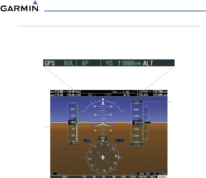
Flight director mode annunciations are displayed on the PFD when the flight director is active. Autopilot status is displayed in the center of the AFCS Status Box. Lateral flight director modes are displayed on the left and vertical on the right. Armed modes are displayed in white and active in green.
Lateral Modes |
Autopilot |
Vertical Modes |
||||||||
Status |
||||||||||
|
|
|
|
|
|
|
|
|
|
|
|
|
|
|
|
|
|
|
|
|
|
|
|
|
|
|
|
|
|
|
|
|
Armed |
Active |
|
Active |
Mode |
Armed |
|||||
|
|
|
|
|
|
|
Reference |
|
|
|
AFCS Status Box
Selected
Altitude
Command
Bars
Figure 7-2 PFD AFCS Display
190-00498-03 Rev.A |
Garmin G1000 Pilot’s Guide for Cessna Nav III |
7-5 |
AUTOMATIC FLIGHT CONTROL SYSTEM
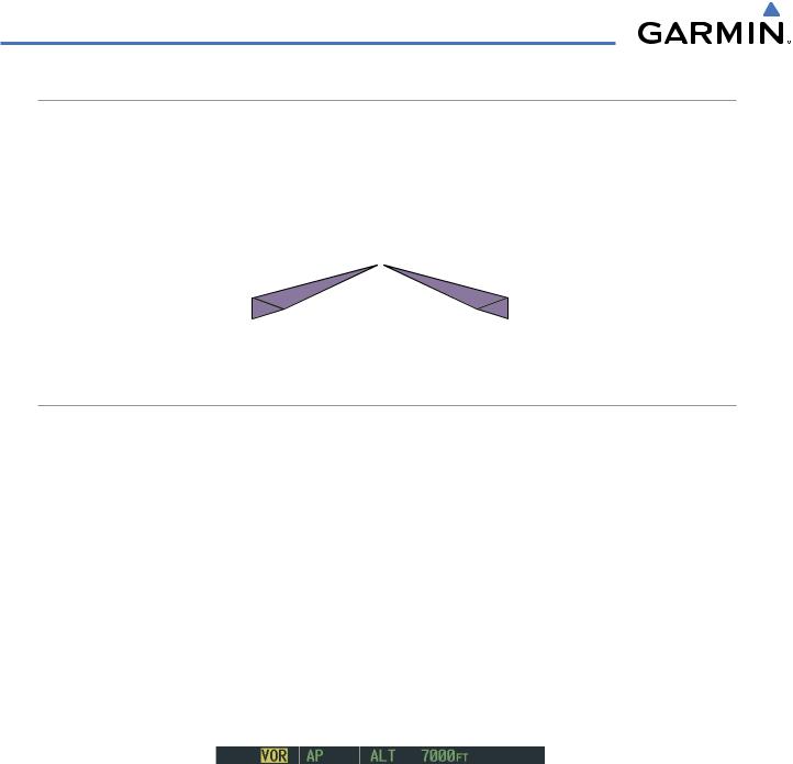
COMMAND BARS
Upon activation of the flight director, Command Bars are displayed on the PFD as a single magenta cue. The Command Bars move together vertically to indicate pitch commands, and bank left or right to indicate roll commands. The Command Bars do not override the aircraft symbol.
If the attitude information sent to the flight director becomes invalid or unavailable, the Command Bars are removed from the display. The flight director Command Bars also disappear if the pitch exceeds +30˚/-20˚ or bank exceeds 65˚.
Figure 7-3 Command Bars
FLIGHT DIRECTOR MODES
Flight director modes are normally selected independently for the pitch and roll axes. Unless otherwise specified, all mode keys are alternate action (i.e., press on, press off). In the absence of specific mode selection, the flight director reverts to the default pitch and/or roll modes(s).
Armed modes are annunciated in white and active in green in the AFCS Status Box. Under normal operation when the control for the active flight director mode is pressed, the flight director reverts to the default modes(s) for the axis(es). Automatic transition from armed to active mode is indicated by the white armed mode annunciation moving to the green active mode field and flashing for 10 seconds.
If the information required to compute a flight director mode becomes invalid or unavailable, the flight director automatically reverts to the default mode for that axis. A flashing yellow mode annunciation and annunciator light indicate loss of sensor (ADC) or navigation data (VOR, LOC, GPS, WAAS) required to compute commands. When such a loss occurs, the system automatically begins to roll the wings level (enters Roll Hold Mode) or maintain the pitch angle (enters Pitch Hold Mode), depending on the affected axis. The flashing annunciation stops when the affected mode key is pressed or another mode for the axis is selected. If after 10 seconds no action is taken, the flashing annunciation stops.
Figure 7-4 Loss of VOR Signal
The flight director is automatically disabled if the attitude information required to compute the default flight director modes becomes invalid or unavailable.
7-6 |
Garmin G1000 Pilot’s Guide for Cessna Nav III |
190-00498-03 Rev.A |