

- •Section 1 System Overview
- •1.1 System Description
- •1.2 Line Replaceable Units (LRU)
- •1.3 G1000 Controls
- •PFD/MFD Controls
- •Audio Panel Controls
- •1.4 Secure Digital (SD) Cards
- •1.5 System Power-up
- •1.6 System Operation
- •Normal Display Operation
- •Reversionary Display Operation
- •AHRS Operation
- •G1000 System Annunciations
- •Softkey Function
- •GPS Receiver Operation
- •1.7 Accessing G1000 Functionality
- •Menus
- •MFD Page Groups
- •MFD System Pages
- •1.8 Display Backlighting
- •Automatic Adjustment
- •Manual Adjustment
- •Section 2 Flight Instruments
- •2.1 Flight Instruments
- •Airspeed Indicator
- •Attitude Indicator
- •Altimeter
- •Vertical Speed Indicator (VSI)
- •Vertical Deviation
- •Horizontal Situation Indicator (HSI)
- •Course Deviation Indicator (CDI)
- •2.2 Supplemental Flight Data
- •Outside Air Temperature
- •Wind Data
- •Vertical Navigation (VNV) Indications
- •2.3 PFD Annunciations and Alerting Functions
- •G1000 System Alerting
- •Marker Beacon Annunciations
- •Traffic Annunciation
- •TAWS Annunciations
- •Altitude Alerting
- •Low Altitude Annunciation
- •Minimum Descent Altitude/Decision Height Alerting
- •2.4 Abnormal Operations
- •Abnormal GPS Conditions
- •Unusual Attitudes
- •Section 3 Engine Indication System (EIS)
- •3.1 Engine Display
- •3.2 Lean Display
- •Normally-aspirated Aircraft
- •Turbocharged Aircraft
- •3.3 System Display
- •Section 4 audio panel and CNS
- •4.1 Overview
- •MFD/PFD Controls and Frequency Display
- •Audio Panel Controls
- •4.2 COM Operation
- •COM Transceiver Selection and Activation
- •COM Transceiver Manual Tuning
- •Quick-Tuning and Activating 121.500 MHz
- •Auto-tuning the COM Frequency
- •Frequency Spacing
- •Automatic Squelch
- •Volume
- •4.3 NAV Operation
- •NAV Radio Selection and Activation
- •NAV Receiver Manual Tuning
- •Auto-tuning a NAV Frequency from the MFD
- •Marker Beacon Receiver
- •DME Tuning (Optional)
- •4.4 GTX 33 Mode S Transponder
- •Transponder Controls
- •Transponder Mode Selection
- •Entering a Transponder Code
- •IDENT Function
- •Flight ID Reporting
- •4.5 Additional Audio Panel Functions
- •Power-Up
- •Mono/Stereo Headsets
- •Speaker
- •Intercom
- •Passenger Address (PA) System
- •Clearance Recorder and Player
- •Entertainment Inputs
- •4.6 Audio Panel Preflight Procedure
- •4.7 Abnormal Operation
- •Stuck Microphone
- •COM Tuning Failure
- •Audio Panel Fail-Safe Operation
- •Reversionary Mode
- •Section 5 Flight Management
- •5.1 Introduction
- •Navigation Status Box
- •5.2 Using Map Displays
- •Map Orientation
- •Map Range
- •Map Panning
- •Measuring Bearing and Distance
- •Topography
- •Map Symbols
- •Airways
- •Track Vector
- •Wind Vector
- •Nav Range Ring
- •Fuel Range Ring
- •5.3 Waypoints
- •Airports
- •Intersections
- •NDBs
- •VORs
- •User Waypoints
- •5.4 Airspaces
- •5.5 Direct-to-Navigation
- •5.6 Flight Planning
- •Flight Plan Creation
- •Adding Waypoints To An Existing Flight Plan
- •Adding Airways to a Flight Plan
- •Adding Procedures To A Stored Flight Plan
- •Flight Plan Storage
- •Flight Plan Editing
- •Along Track Offsets
- •Parallel Track
- •Activating a Flight Plan Leg
- •Inverting a Flight Plan
- •Flight Plan Views
- •Closest Point of FPL
- •5.7 Vertical Navigation
- •Altitude Constraints
- •5.8 Procedures
- •Departures
- •Arrivals
- •Approaches
- •5.9 Trip Planning
- •Trip Planning
- •5.10 RAIM Prediction
- •5.11 Navigating a Flight Plan
- •5.12 Abnormal Operation
- •Section 6 Hazard Avoidance
- •6.1 XM Satellite Weather
- •Activating Services
- •Using XM Satellite Weather Products
- •6.2 WX-500 Stormscope (Optional)
- •Setting Up Stormscope on the Navigation Map
- •Selecting the Stormscope Page
- •6.3 Terrain Proximity
- •Displaying Terrain Proximity Data
- •Terrain Proximity Page
- •6.4 TAWs (Optional)
- •Displaying TAWS Data
- •TAWS Page
- •TAWS Alerts
- •System Status
- •6.5 Traffic Information Service (TIS)
- •Displaying TRAFFIC Data
- •Traffic Map Page
- •TIS Alerts
- •System Status
- •6.6 Traffic Advisory System (TAS) (Optional)
- •TAS Symbology
- •Operation
- •Altitude Display
- •Traffic Map Page Display Range
- •TAS Alerts
- •System Status
- •6.7 ADS-B Traffic (Optional)
- •Section 7 Automatic Flight Control System
- •7.2 Flight Director Operation
- •Activating the Flight Director
- •AFCS Status Box
- •Command Bars
- •Flight Director Modes
- •7.3 Vertical Modes
- •Pitch Hold Mode (PIT)
- •Selected Altitude capture Mode (ALTs)
- •Altitude hold mode (alt)
- •Vertical Speed Mode (VS)
- •Flight Level Change Mode (FLC)
- •Vertical Navigation Modes (VPTH, ALTV)
- •Glidepath Mode (GP) (waas only)
- •Glideslope Mode (GS)
- •Go Around (GA) Mode
- •7.4 Lateral Modes
- •Roll Hold Mode (ROL)
- •Heading Select Mode (HDG)
- •Navigation mode (GPS, VOR, LOC)
- •Approach mode (GPS, VAPP, LOC)
- •Backcourse Mode (BC)
- •7.5 Autopilot Operation
- •Engaging the Autopilot
- •Control Wheel Steering
- •Disengaging the Autopilot
- •7.6 Example Procedures
- •Departure
- •Intercepting a VOR Radial
- •Flying a Flight Plan/GPS Course
- •Descent
- •Approach
- •Go Around/Missed Approach
- •7.7 AFCS Annunciations and Alerts
- •AFCS Status Alerts
- •Overspeed Protection
- •Section 8 Additional Features
- •8.1 SafeTaxi
- •SafeTaxi Cycle Number and Revision
- •8.2 ChartView
- •ChartView Softkeys
- •Terminal Procedures Charts
- •Chart Options
- •Day/Night View
- •ChartView Cycle Number and Expiration Date
- •8.3 FliteCharts
- •FliteCharts Softkeys
- •Terminal Procedures Charts
- •Chart Options
- •Day/Night View
- •FliteCharts Cycle Number and Expiration Date
- •8.4 XM Radio Entertainment (Optional)
- •Activating XM Satellite Radio Services
- •Using XM Radio
- •Automatic Audio Muting
- •8.5 Scheduler
- •8.5 Abnormal Operation
- •Annunciations and Alerts
- •Alert Level Definitions
- •Nav III Aircraft Alerts
- •CO Guardian Messages
- •G1000 System Annunciations
- •Other G1000 Aural Alerts
- •G1000 System Message Advisories
- •AFCS Alerts
- •TAWS ALERTS
- •TAWS System Status Annunciations
- •SD Card Use
- •Jeppesen Databases
- •Garmin Databases
- •Glossary
- •Frequently Asked Questions
- •General TIS Information
- •Introduction
- •TIS vs. TAS/TCAS
- •TIS Limitations
- •Map Symbols
- •Index
FLIGHT MANAGEMENT
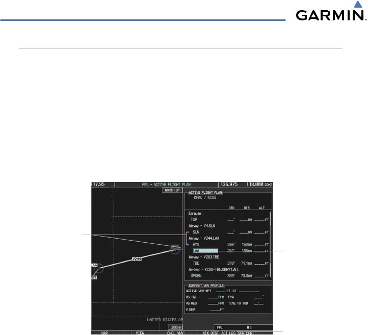
ACTIVATING A FLIGHT PLAN LEG
The G1000 allows selection of a highlighted leg as the “active leg” (the flight plan leg which is currently used for navigation guidance).
Activating a flight plan leg:
1)Press the FPL Key to display the Active Flight Plan Page (MFD) or the Active Flight Plan Window (PFD)
2)Press the FMS Knob to activate the cursor (not required on the PFD) and turn the large FMS Knob to highlight the destination waypoint for the desired leg.
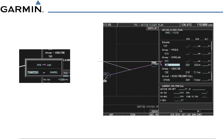
3)Press the ACT LEG Softkey (MFD only); or press the MENU Key,highlight ‘Activate Leg’, and press the ENT Key. A confirmation window is displayed with ‘ACTIVATE’ highlighted.
4)Press the ENT Key to activate the flight plan leg. To cancel, press the CLR Key, or highlight ‘CANCEL’ and press the ENT Key.
Current Active Leg
Selected Destination
Waypoint
Activate Leg Softkey
Figure 5-79 Active Flight Plan Page - Selecting the Leg Destination Waypoint
5-80 |
Garmin G1000 Pilot’s Guide for Cessna Nav III |
190-00498-03 Rev.A |
FLIGHT MANAGEMENT
New Active
Flight Plan Leg
Confirmation Window
Figure 5-80 Active Flight Plan Page - New Active Leg
INVERTING A FLIGHT PLAN
Any flight plan may be inverted (reversed) for navigation back to the original departure point.
Inverting the active flight plan:
1)Press the FPL Key to display the Active Flight Plan Page (MFD) or the Active Flight Plan Window (PFD)
2)Press the MENU Key, highlight ‘Invert Flight Plan’, and press the ENT Key. An ‘Invert Active Flight Plan?’ confirmation window is displayed.
3)Select ‘OK’.
4)Press the ENT Key to invert and activate the active flight plan. To cancel, press the CLR Key, or highlight ‘CANCEL’ and press the ENT Key.
Inverting and activating a stored flight plan:
1)Press the FPL Key on the MFD to display the Active Flight Plan Page.
2)Turn the small FMS Knob clockwise one click to display the Flight Plan Catalog Page.
3)Press the FMS Knob to activate the cursor and turn the FMS Knob to highlight the flight plan to be inverted.
4)Press the INVERT Softkey; or press the MENU Key, select ‘Invert & Activate Flight Plan’ and press the ENT Key. An ‘Invert and activate stored flight plan?’ confirmation window is displayed.
5)Select ‘OK’.
6)Press the ENT Key to invert and activate the stored flight plan. To cancel, press the CLR Key, or highlight ‘CANCEL’ and press the ENT Key.
190-00498-03 Rev.A |
Garmin G1000 Pilot’s Guide for Cessna Nav III |
5-81 |
FLIGHT MANAGEMENT
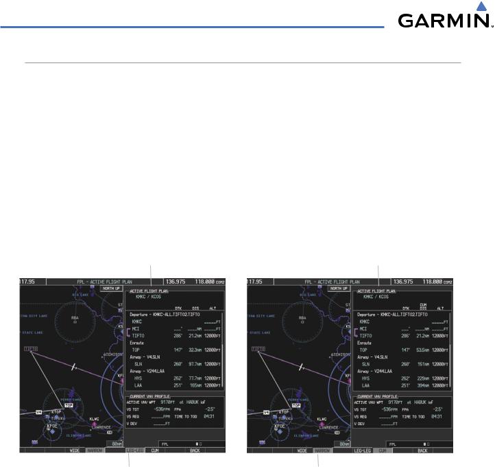
FLIGHT PLAN VIEWS
Information about flight plans can be viewed in more than one way. The active flight plan can be configured to show cumulative distance over the length of the flight plan or the distance for each leg of the flight plan; and the active flight plan can be viewed in a narrow or wide view. In the wide view, additional information is displayed: Fuel Remaining (FUEL REM), Estimated Time Enroute (ETE), Estimated Time of Arrival (ETA), and Bearing to the waypoint (BRG).
Switching between leg-to-leg waypoint distance and cumulative waypoint distance:
1)Press the FPL Key on the MFD to display the Active Flight Plan Page.
2)Press the VIEW Softkey to display the CUM and LEG-LEG Softkeys.
3)Press the CUM Softkey to view cumulative waypoint distance, or press the LEG-LEG Softkey to view leg-to-leg waypoint distance.
4)Press the BACK Softkey to return to the top level active flight plan softkeys.
Active Flight Plan Leg to Leg Distance |
Active Flight Plan Cumulative Distance |
||||||
|
|
|
|
|
|
|
|
|
|
|
|
|
|
|
|
|
|
|
|
|
|
|
|
|
|
|
|
|
|
|
|
WIDE Softkey, NARROW Softkey, LEG-LEG Softkey, CUM Softkey
Figure 5-81 Active Flight Plan - Leg to Leg vs. Cumulative Distance
Switching between wide and narrow view:
1)Press the FPL Key on the MFD to display the Active Flight Plan Page.
2)Press the VIEW Softkey to display the WIDE and NARROW Softkeys.
3)Press the WIDE Softkey to display the wide view, or press the NARROW Softkey to display the narrow view.
4)Press the BACK Softkey to return to the top level active flight plan softkeys.
5-82 |
Garmin G1000 Pilot’s Guide for Cessna Nav III |
190-00498-03 Rev.A |
FLIGHT MANAGEMENT
Active Flight Plan Leg to Leg Distance |
|
Active Flight Plan Cumulative Distance |
||||||
|
|
|
|
|
|
|
|
|
|
|
|
|
|
|
|
|
|
|
|
|
|
|
|
|
|
|
|
|
|
|
|
|
|
|
|
|
|
|
|
|
|
|
|
|
|
|
|
|
|
|
|
|
|
WIDE Softkey, NARROW Softkey, LEG-LEG Softkey, CUM Softkey
Figure 5-82 Active Flight Plan - Wide vs. Narrow View
COLLAPSING AIRWAYS
The G1000 allows airways on the active flight plan to be collapsed or expanded from the Active Flight Plan Page/Window. When airways have been collapsed, it is indicated on the airway heading.
When airways are collapsed, leg-to-leg computed values such as DIS or ETE shown for the exit waypoint reflects the total of all the legs on the airway that have been hidden in the collapsed display. The DTK value is inhibited because it is not usable in this context.
The Active Flight Plan Page always keeps the following three waypoints visible: “From” waypoint, “To” waypoint,andthe“Next”waypoint. Topreventoneormoreofthesewaypointsfrombeinghiddeninacollapsed airway segment, the airway segment that contains either the “To” or the “Next” waypoint is automatically expanded. When an airway is loaded, airways are automatically expanded to facilitate flight plan review.
Q3.FEPOT Airway
Collapsed View
Expanded View
Figure 5-83 Expanded/Collapsed Airways
190-00498-03 Rev.A |
Garmin G1000 Pilot’s Guide for Cessna Nav III |
5-83 |