

FLIGHT INSTRUMENTS
COURSE DEVIATION INDICATOR (CDI)
 NOTE: If a heading change of greater than 105° with respect to the course is made, the CDI on the Arc HSI switches to the opposite side of the deviation scale and displays reverse sensing.
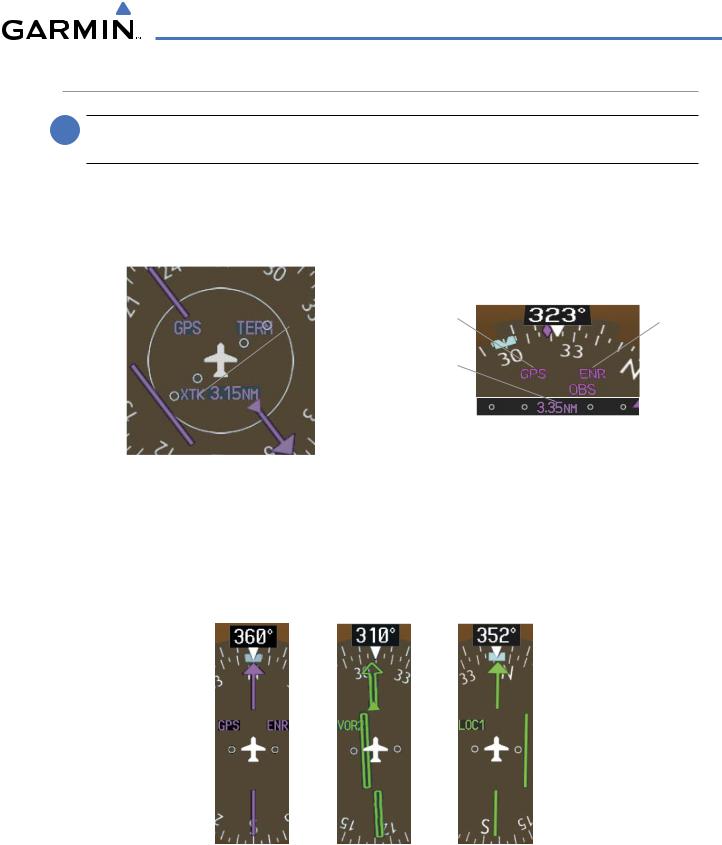
The Course Deviation Indicator (CDI) moves left or right from the course pointer along a lateral deviation scale to display aircraft position relative to the course. If the course deviation data is not valid, the CDI is not displayed.
360º HSI
|
|
|
|
|
|
|
|
|
|
|
|
|
Flight |
|
|
Arc HSI |
||
|
|
|
|
|
|
|
|
|
|
|
|
|
|
|
|
|
|
|
Navigation |
|
|
|
|
|
|
|
|
|
|
|
|
Phase |
Navigation |
|
|
Flight |
|
|
|
|
|
|
|
|
|
|
|
|
|
|
|
|||||
|
|
|
|
|
|
|
|
|
|
|
|
|
Source |
|
|
|||
|
|
|
|
|
|
|
|
|
|
|
|
|
|
Phase |
||||
Source |
|
|
|
|||||||||||||||
|
|
|
|
|
||||||||||||||
|
|
|
|
|
|
|
|
|
|
|
|
|
Scale |
Crosstrack |
|
|
|
|
|
|
|
|
|
|
|
|
|
|
|
|
|
Error |
|
|
|
||
|
|
|
|
|
|
|
|
|
|
|
Crosstrack |
|
|
|
||||
|
|
|
|
|
|
|
|
|
|
|
|
|
|
|
|
|||
CDI |
|
|
|
|
|
|
|
|
|
|
|
Error |
CDI Scale |
|
|
|
CDI |
|
|
|
|
|
|
|
|
|
|
|
|
|
|
|
|||||
|
|
|
|
|
|
|
|
|
|
|
|
|
|
|
||||
|
|
|
|
|
|
|
|
|
|
|
|
|
||||||
|
|
|
|
|
|
|
|
|
|
|
|
|
|
|
|
|
||
|
|
|
|
|
|
|
|
|||||||||||
Figure 2-21 Course Deviation Indicator
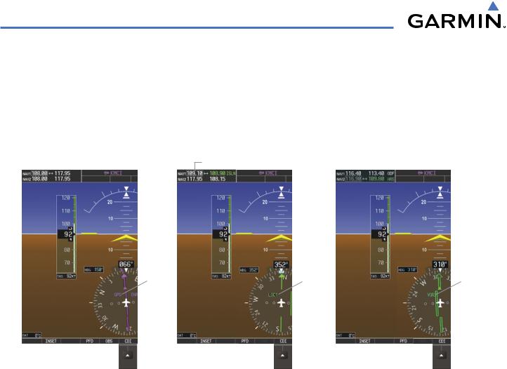
The CDI can display two sources of navigation: GPS or NAV (VOR, localizer). Color indicates the current navigation source: magenta (for GPS) or green (for VOR and LOC). The full scale limits for the CDI are defined by a GPS derived distance when coupled to GPS. When coupled to a VOR or localizer (LOC), the CDI has the same angular limits as a mechanical CDI. If the CDI exceeds the maximum deviation on the scale (two dots) while coupled to GPS, the crosstrack error (XTK) is displayed below the white aircraft symbol.
Figure 2-22 Navigation Sources
190-00498-03 Rev.A |
Garmin G1000 Pilot’s Guide for Cessna Nav III |
2-15 |
FLIGHT INSTRUMENTS
Changing navigation sources:
1)Press the CDI Softkey to change from GPS to VOR1 or LOC1. This places the light blue tuning box over the NAV1 standby frequency in the upper left corner of the PFD.
2)Press the CDI Softkey again to change from VOR1 or LOC1 to VOR2 or LOC2. This places the light blue tuning box over the NAV2 standby frequency.
3)Press the CDI Softkey a third time to return to GPS.
NAV1 Selected for Tuning |
|
NAV2 Selected for Tuning |
|
||
|
|
|
GPS |
LOC1 |
VOR2 |
Selected |
Selected |
Selected |
Pressing the CDI Softkey Cycles
through Navigation Sources 
Figure 2-23 Selecting a Navigation Source
ThesystemautomaticallyswitchesfromGPStoLOCnavigationsourceandchangestheCDIscalingaccordingly when all of the following occur:
•A localizer or ILS approach has been loaded into the active flight plan
•The Final Approach Fix (FAF) is the active leg, the FAF is less than 15 nm away, and the aircraft is moving toward the FAF
•A valid localizer frequency has been tuned
•The GPS CDI deviation is less than 1.2 times full-scale deflection
GPS steering guidance is still provided after the CDI automatically switches to LOC until LOC capture, up to the Final Approach Fix (FAF) for an ILS approach, or until GPS information becomes invalid. Activating a Vector-to-Final (VTF) approach (see the Flight Management Section) also causes the CDI to switch to LOC navigation source; GPS steering guidance is not provided after this switch.
2-16 |
Garmin G1000 Pilot’s Guide for Cessna Nav III |
190-00498-03 Rev.A |
FLIGHT INSTRUMENTS
GPS CDI SCALING
When GPS is the selected navigation source, the flight plan legs are sequenced automatically and annunciations appear on the HSI for the flight phase. Flight phase annunciations are normally shown in magenta, but when cautionary conditions exist the color changes to yellow. If the current leg in the flight plan is a heading leg, ‘HDG LEG’ is annunciated in magenta beneath the aircraft symbol.
The current GPS CDI scale setting is displayed as ‘System CDI’ on the AUX - System Setup Page and the fullscale deflection setting may also be changed (2.0 nm, 1.0 nm, 0.3 nm, or Auto) from this page (Figure 2-24). If the selected scaling is smaller than the automatic setting for enroute and terminal phases, the CDI is scaled accordingly and the selected setting is be displayed rather than the flight phase annunciation.
Changing the selected GPS CDI setting:
1)Use the FMS Knob to select the AUX - System Setup Page on the MFD.
2)Press the FMS Knob to activate the cursor.
3)Turn the large FMS Knob to highlight ‘Selected’ in the ‘GPS CDI’ box.
4)Turn the small FMS Knob to highlight the desired setting and press the ENT Key.
5)To cancel the selection, press the FMS Knob or the CLR Key.
Figure 2-24 System Setup Page,
GPS CDI Settings
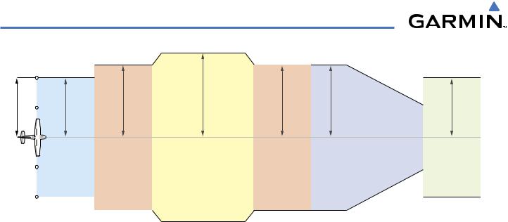
When set to ‘Auto’ (default), the GPS CDI scale automatically adjusts to the desired limits based upon the current phase of flight (Figure 2-25, Table 2-1).
190-00498-03 Rev.A |
Garmin G1000 Pilot’s Guide for Cessna Nav III |
2-17 |
FLIGHT INSTRUMENTS
scale Deflection |
0.3 nm |
1.0 nm |
2.0 nm |
1.0 nm |
1.0 nm |
CDI Full- |
|
|
|
|
|
Departure |
Terminal |
Enroute |
Terminal |
|
(Oceanic if >200 nm |
||||
|
|
|
from nearest airport) |
|
|
|
|
|
|
|
|
|
|
|
Refer to accompanying approach CDI scaling figures
Approach
0.3 nm
Missed
Approach
Figure 2-25 Automatic CDI Scaling
•When a departure procedure is activated, the CDI is scaled for departure (0.3 nm).
•The system switches from departure to terminal CDI scaling (1.0 nm) under the following conditions:
-The next leg in the departure procedure is not aligned with the departure runway
-The next leg in the departure procedure is not a CA, CD, CF, CI, CR, DF, FA, FC, FD, FM, IF, or TF leg (see Glossary for leg type definitions)
-After any leg in the departure procedure that is not a CA or FA leg
•At 30 nm from the departure airport the enroute phase of flight is automatically entered and CDI scaling changes to 2.0 nm over a distance of 1.0 nm, except under the following conditions:
-When navigating with an active departure procedure, the flight phase and CDI scale does not change until the aircraft arrives at the last departure waypoint (if more than 30 nm from the departure airport) or the leg after the last departure waypoint has been activated or a direct-to waypoint is activated.
•If after completing the departure procedure the nearest airport is more than 200 nm away from the aircraft and the approach procedure has not yet commenced, the CDI is scaled for oceanic flight (2.0 nm).
•Within 31 nm of the destination airport (terminal area), the CDI scale gradually ramps down from 2.0 nm to 1.0 nm over a distance of 1.0 nm, except under the following conditions:
-When navigating with an active arrival route, the flight phase and CDI scale does not change until the aircraft arrives at the first waypoint in the arrive route (if within 31 nm from the destination airport).
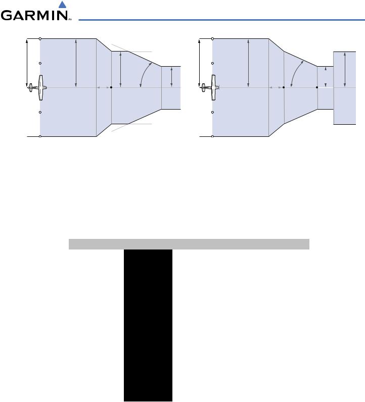
•During approach, the CDI scale ramps down even further (see Figures 2-26 and 2-27). This transition normally occurs within 2.0 nm of the Final Approach Fix (FAF). The CDI switches to approach scaling automatically once the approach procedure becomes active or if Vectors-To-Final (VTF) are selected.
-If the active waypoint is the FAF, the ground track and the bearing to the FAF must be within 45° of the final approach segment course.
-If the active waypoint is part of the missed approach procedure, the active leg and the preceding missed approach legs must be aligned within 3° of the final approach segment course and the aircraft position must be prior to the turn initiation point.
2-18 |
Garmin G1000 Pilot’s Guide for Cessna Nav III |
190-00498-03 Rev.A |
FLIGHT INSTRUMENTS
scale-FullCDIDeflection |
1.0nm |
CDI scale is set to the smaller of 0.3 nm |
||
nm0.3 |
|
ft350 |
||
|
|
|
or an angle set by the system |
|
|
|
|
angle set |
|
|
|
|
by system |
|
|
|
2 nm |
|
|
|
|
FAF |
|
|
CDI scale varies if VTF is activated
CDI Full-scale Deflection
1.0 nm
2 nm
FAF
CDI scale varies if VTF is activated
angle based |
width |
|
|
0.3 nm |
|
||||
on database |
course |
|
|
|
information |
|
|
|
|
|
|
|
|
|
|
|
|
|
|
Landing |
|
|||
Threshold |
|
|||
Figure 2-26 Typical LNAV and LNAV+V Approach CDI Scaling |
Figure 2-27 Typical LNAV/VNAV and LPV Approach CDI Scaling |
•When a missed approach is activated, the CDI scale changes to 0.3 nm.
•The system automatically switches back to terminal mode under the following conditions:
-If the next leg in the missed approach procedure is not aligned with the final approach path
-If the next leg in the missed approach procedure is not a CA, CD, CF, CI, CR, DF, FA, FC, FD, FM, IF, or TF leg
-After any leg in the missed approach procedure that is not a CA or FA leg
Flight Phase |
Annunciation* |
Automatic CDI Full-scale Deflection |
|
Departure |
DPRT |
0.3 nm |
|
Terminal |
TERM |
1.0 nm |
|
Enroute |
ENR |
2.0 nm |
|
Oceanic |
OCN |
2.0 nm |
|
Approach |
LNAV |
|
|
(Non-precision) |
|
||
|
1.0 nm decreasing to 350 feet depending on |
||
|
|
||
Approach |
|
variables (see Figure 2-26) |
|
(Non-precision with |
LNAV + V |
|
|
Vertical Guidance) |
|
|
|
Approach |
L/VNAV |
|
|
(LNAV/VNAV) |
1.0 nm decreasing to a specified course width, then |
||
|
|||
Approach |
LPV |
0.3 nm, depending on variables (see Figure 2-27) |
|
(LPV) |
|
||
|
|
||
Missed Approach |
MAPR |
0.3 nm |
Table 2-1 Automatic GPS CDI Scaling
190-00498-03 Rev.A |
Garmin G1000 Pilot’s Guide for Cessna Nav III |
2-19 |
FLIGHT INSTRUMENTS
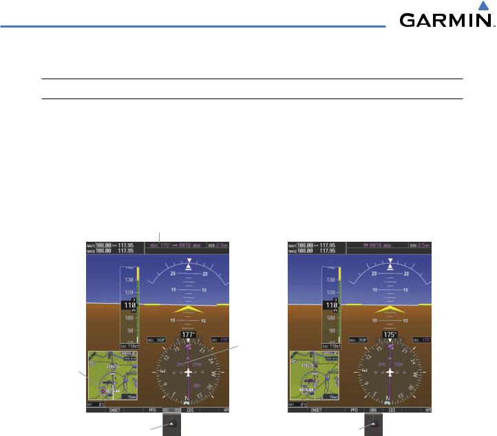
OBS MODE
 NOTE: VNV is inhibited while automatic waypoint sequencing has been suspended.
Enabling Omni-bearing Selector (OBS) Mode suspends the automatic sequencing of waypoints in a GPS flight plan (GPS must be the selected navigation source), but retains the current “active-to” waypoint as the navigation reference even after passing the waypoint. ‘OBS’ is annunciated to the lower right of the aircraft symbol when OBS Mode is selected (see Figure 2-28).
While OBS Mode is enabled, a course line is drawn through the “active-to” waypoint on the moving map. If desired, the course to/from the waypoint can now be adjusted. When OBS Mode is disabled, the GPS flight plan returns to normal operation with automatic sequencing of waypoints, following the course set in OBS Mode. The flight path on the moving map retains the modified course line.
OBS Course
|
|
GPS |
Extended |
Selected |
|
|
|
|
Course |
OBS Mode |
|
Line |
||
Pressing the OBS |
|
Enabled |
|
||
|
Pressing the OBS |
|
Softkey Enables |
|
Softkey Again Returns |
OBS Mode |
|
to Normal Operation |
Figure 2-28 |
Omni-bearing Selector (OBS) Mode |
|
2-20 |
Garmin G1000 Pilot’s Guide for Cessna Nav III |
190-00498-03 Rev.A |
FLIGHT INSTRUMENTS
Enabling/disabling OBS Mode while navigating a GPS flight plan:
1)Press the OBS Softkey to select OBS Mode.
2)Turn the CRS Knob to select the desired course to/from the waypoint. Press the CRS Knob to synchronize the Selected Course with the bearing to the next waypoint.
3)Press the OBS Softkey again to return to automatic waypoint sequencing.
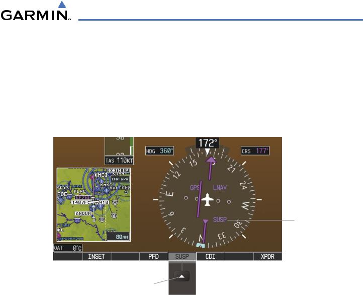
As the aircraft crosses the missed approach point (MAP), automatic approach waypoint sequencing is suspended. ‘SUSP’ appears on the HSI (to the lower right of the aircraft symbol) in place of ‘OBS’ and the OBS Softkey label changes to SUSP.
SUSP
Annunciation
Pressing the SUSP Softkey Suspends
Automatic Waypoint Sequencing
Figure 2-29 Suspending Automatic Waypoint Sequencing
190-00498-03 Rev.A |
Garmin G1000 Pilot’s Guide for Cessna Nav III |
2-21 |