

схемотехника / Manuals_Handb№cher / ALPHA / English / Alpha_Programming_Manual_versC_ENGLISH
.pdfα Simple Application Controllers |
Lets Make a Program 7 |
|
|
7.Lets Make a Program
Lets create a sample program from beginning to end. Power up the Alpha and press any key to go the Run Menu.
7.1Option Settings
Before starting to program, we can set any desired options from the following list.
Language (this one might be important!): page 3-3.
Real Time Clock Set: page 3-3.
Others: Password, Summertime Clock, Menu Key, and ModemInit: page 3-4.
For the program below, none of the above options need be set. Use the ProgClear to erase the current memory contents with OK. To confirm the memory erase, press OK again.
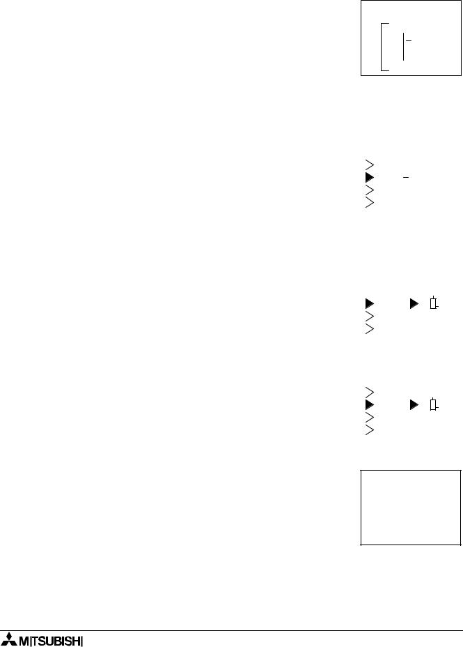
7.2The Function Block Diagram
The system Inputs I01, I02, and I03 are shown on the left of the diagram and the system Outputs O01, O02, and O03 are shown on the right. The function blocks are numbered in the order that they are added to the program.
I01 |
|
|
|
|
|
S |
B01 |
|
|
|
|
O 01 |
1 |
|
|
C |
|
S |
|
|
|||||
|
|
|
|
|
|
|
|
|||||
|
|
|
|
|
|
|
|
|||||
I02 |
B02 |
|
|
B03 |
|
O 02 |
||||||
|
2 |
|
|
|
|
|
|
|||||
|
|
|
|
|
|
|
|
|
|
|||
|
|
|
|
|
|
O N E SH O T |
|
|
|
|
||
I03 |
|
|
3 |
|
R |
|
|
|
||||
|
|
|
|
|
|
|
|
|
|
|||
4 |
|
|
|
|
|
|
|
|
||||
|
|
|
|
|
|
|
|
|
|
|||
|
|
|
|
O R |
|
|
|
|
|
|
|
|
|
|
|
|
|
|
|
|
|
SET/R ESET |
|
||
|
|
|
|
|
|
|
|
|
O 03 |
|||
|
|
|
|
|
|
|
|
|
|
|
|
|
|
|
|
|
|
|
|
|
|
|
|
|
|
|
|
|
|
|
|
|
|
|
|
|
|
|
The input pins are shown on the left side of the FB and Outputs while output pins are shown on the right side of the blocks. Note that each input pin can receive only one signal but the output pins can provide signals to multiple sources.
7 - 1

α Simple Application Controllers |
Lets Make a Program 7 |
|
|
7.3Input the Program
The options are set and the Function Block diagram is finished. It is time to start inputting the program. Enter ProgEdit to begin programming.
If during the course of the programming you wish to begin again, use the ESC key to enter the Edit Menu (you might have to press the key more than once). Use the Exit option to go back to the Top Menu. Erase the memory with ProgClear and you can begin again.
7.3.1Adding Function Blocks by the Left to Right method (Section 4.2.1)
The first block that is shown will be the Input Block I01 with the Input
|
number 01 flashing. Press the “+” key or “-” key to scroll through |
|
|
|
|
|
|
|
|
|
|
|
|
|
|
|
|
|
|
|
|
|
|
|
|
|
||||
|
available programming blocks including Outputs, M bits, Keys, and |
|
|
|
0 1 |
|
|
|
|
|
|
|
|
|
|
|
|
|
|
|
|
|
||||||||
|
|
|
|
|
|
|
|
|
|
|
|
|
|
|
|
|
|
|
||||||||||||
|
the Inputs. Return to I01. Press the ( ) arrow key. The output pin |
|
|
|
|
|
|
|
|
|
|
|
|
|
|
|
|
|
|
|
|
|
|
|
|
|
||||
|
|
|
|
|
|
|
|
|
|
|
|
|
|
|
|
|
|
|
|
|
|
|
|
|
||||||
|
should now be flashing. |
|
|
|
|
|
|
|
|
|
|
|
|
|
|
|
|
|
|
|
|
|
|
|
|
|
|
|
|
|
|
Enter “+” to add a function block to Input I01. The options available |
|
|
|
|
|
I n |
|
|
|
|
|
|
|
|
|
|
|
|
|
|
|
|
|||||||
|
|
|
|
|
|
|
|
|
|
|
|
|
|
|
|
|
|
|
||||||||||||
|
|
|
|
|
|
|
|
|
|
|
|
|
|
|
|
|
|
|
|
|
|
|
|
|
|
|
||||
|
|
|
|
|
|
|
|
|
|
|
|
|
|
|
|
|
|
|
|
|
|
|
|
|
|
|
||||
|
|
|
|
|
|
|
|
|
|
|
|
|
|
|
|
|
|
|
|
|
|
|
|
|
|
|||||
|
to connect to the Input block will be shown on the right hand side of |
|
|
|
|
|
|
|
|
|
|
|
|
|
|
|
|
|
|
|
|
|
|
|
|
|
|
|||
|
the screen. Use the ( |
) and ( |
) arrows to move to the option to |
|
|
|
0 1 |
|
|
|
|
|
|
|
|
|
|
|
|
|
|
|
|
|
||||||
|
|
|
|
|
|
|
|
|
|
|
|
|
|
|
|
|
|
|
|
|||||||||||
|
select, AddFB. Enter OK (Section 4.4.2). |
|
|
|
|
|
|
|
|
|
|
|
|
|
|
A d d F B |
|
|||||||||||||
|
|
|
|
|
|
|
|
|
|
|
|
|
|
|
||||||||||||||||
|
|
|
|
|
|
|
|
|
|
|
|
|
|
|
||||||||||||||||
|
|
|
|
|
|
|
|
|
|
|
|
|
|
|
|
|
|
|
O 0 1 |
|
||||||||||
|
|
|
|
|
|
|
|
|
|
|
|
|
|
|
c t |
|
|
|
|
|
|
|
|
|
|
|
|
|||
|
|
|
|
|
|
C o n n e |
|
|
|
|
|
|
|
|
|
|
|
|
|
|
||||||||||
|
|
|
|
|
|
|
|
|
|
|
|
|
|
|
|
|
|
|
|
|
|
|
|
|
|
|
|
|||
|
The FB select menu containing the twenty-two Function Blocks will |
|
|
|
|
|
|
|
|
|
|
|
|
|
|
|
|
|
|
|
|
|
|
|
|
|
||||
|
|
|
|
|
|
|
|
|
|
|
|
|
|
|
|
|
|
|
|
|
|
|
|
|
||||||
|
appear (picture). Again, use the ( ) and ( ) arrows to scroll to the |
|
|
|
|
|
|
|
|
|
|
|
|
|
|
|
|
|
|
|
|
|
|
|
|
|
||||
|
desired Function Block, in this case the One Shot (OS) Function |
F B S e l e c t |
|
|||||||||||||||||||||||||||
|
Block. |
|
|
|
|
F l i c k e r |
|
|
|
|
|
|
|
|
|
|
|
|
||||||||||||
|
Use the OK button to accept. |
|
|
|
O n e S h o t |
|
||||||||||||||||||||||||
|
|
|
|
|
|
|
O f f s e t |
|
|
|
|
|
|
|
|
|
|
|
|
|||||||||||
|
The OS block has two input pins, the Input Pin on top and the Clear |
|
|
|
|
|
|
|
|
|
|
|
|
|
|
|
|
|
|
|
|
|
|
|
|
|
||||
|
|
|
|
|
|
|
|
|
|
|
|
|
|
|
|
|
|
|
|
|
|
|
|
|
|
|||||
|
|
|
|
|
|
|
|
|
|
|
|
|
|
|
|
|
|
|
|
|
|
|
|
|
||||||
|
Pin beneath. Use the ( |
) and ( |
) arrows to choose the desired pin, |
|
|
|
|
|
|
|
|
|
|
|
|
|
|
|
|
|
|
|
|
|
|
|
|
|
||
|
in this case the Input pin. Confirm with the OK button. The blocks |
|
|
0 1 |
|
|
|
|
|
|
|
0 1 |
|
|
|
|
|
|||||||||||||
|
|
|
|
|
|
|
|
|
||||||||||||||||||||||
|
have been connected! |
|
|
|
|
|
|
|
I n |
|
|
|
|
|
|
|
|
|
|
|
|
|
|
|
|
|
||||
|
|
|
|
|
|
|
|
|
|
|
|
|
|
|
|
|
|
|
|
|
|
|
|
|||||||
|
|
|
|
|
|
|
|
|
|
|
|
|
|
|
|
|
|
|
|
|
|
|
||||||||
|
Use the ( ) arrow twice to move right until the OS output pin is flash- |
|
|
|
|
|
|
|
|
|
|
O S |
|
|
|
|
|
|||||||||||||
|
|
|
|
|
|
|
||||||||||||||||||||||||
|
|
|
|
|
|
|
|
|
|
|
|
|
|
|
|
|
|
|
|
|
|
|
|
|
|
|||||
|
|
|
|
|
|
|
|
|
|
|
|
|
|
|
|
|
|
|
|
|
|
|
|
|
|
|||||
|
|
|
|
|
|
|
|
|
|
|
|
|
|
|
|
|
|
|
|
|
|
|
|
|
||||||
|
ing (picture). Enter the “+” key to add a block. There is no need to |
|
|
|
|
|
|
|
|
|
|
|
|
|
|
|
|
|
|
|
|
|
|
|
|
|
||||
|
enter the AddFB mode because O01 will appear on the list of blocks |
0 1 |
|
|
|
|
|
|
|
|
|
|
|
|
|
|
|
|
|
|||||||||||
|
to add. Use the ( ) and ( ) arrows to scroll to O01, choose with the |
|
|
|
|
|
|
|
|
|
|
|
|
|
|
|
|
|
|
|
|
|
|
|
|
|
||||
|
|
|
|
|
|
|
|
|
|
|
|
|
|
|
|
|
|
|
|
|
|
|
|
|
||||||
|
OK key, and then confirm with the OK key. |
|
|
|
|
|
|
|
|
|
|
|
|
|
|
|
|
|
|
|
|
|
|
|
|
|
||||
|
|
|
|
O S |
|
|
|
|
|
|
|
|
|
|
|
|
||||||||||||||
|
|
|
|
|
|
|
|
|
|
|
|
|
|
|
|
|
|
|
|
|
|
|||||||||
|
|
|
|
|
|
|
|
|
|
|
|
|
|
|
|
|
|
|
|
|
|
|
|
|
|
|
|
|
|
|
|
|
|
|
|
|
|
|
|
|
|
|
|
|
|
|
|
|
|
|
|
|
|
|
|
|
|
|
|
|
|
|
|
|
|
|
|
7 - 2 |
|
|
|
|
|
|
|
|
|
|
|
|
||||||||||||
|
|
|
|
|
|
|
|
|
|
|
|
|
|
|
|
|
|
|||||||||||||
|
|
|
|
|
|
|
|
|
|
|
|
|
|
|
|
|
|
|
|
|
|
|
|
|
|
|
|
|
|
|
α Simple Application Controllers |
Lets Make a Program 7 |
|
|
7.3.2Scroll through the Function Blocks by Number (Section 4.6.1)
When the Output has been connected, move one space to the right so that the Output number “01” is flashing. Use the “+” key to scroll through to Input I02. (You will scroll through the Outputs, Keys, M bits, and finally get to the Inputs).
Move to the right one space so that the output pin is flashing. Connect I02 to the OR block, (the same procedure as connecting I01 to the One Shot Block). The input pins for the OR Block are equivalent so that any input pin can be chosen. [The key sequence for the OR Block addition is OK, scroll to AddFB, OK, scroll to OR, OK, OK].
Move right until the OR output pin is flashing. Connect Output O03 in the same manner that O01 was added. [The key sequence will be OK, scroll to O03, OK, OK].
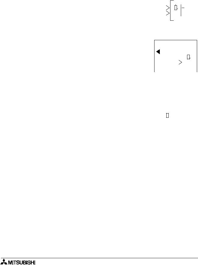
With the OR output pin still flashing (see diagram at right), press the “+” key again. The output pin of the OR block can be connected to another location.
Scroll to “B01OS” and enter OK. The OR block and the OS block can now be connected through the Clear pin (picture). Since the OS Input pin on top has already been filled, there can be no further connection to that pin.
Press OK to accept the connection to the “C”, or Clear pin.
B 01 0 1
Out
|
|
|
|
|
|
|
|
|
|
|
|
|
0 2 |
|
|
|
0 3 |
|
|
|
|
||
|
|
|
|
|
I |
|
|
|
|
|
|
|
|
O R |
|
|
|
O u |
|
t |
|||
|
|
|
|
|
|
|
|||||
|
|
|
|
||||||||
|
|
|
|
|
|
|
|
|
|
|
|
C o n n e c t |
|
|
|
|
|
|
|
|
|
|
||||
|
|
|
|
= C |
|
|
|
|
|
|
|
|
|
|
|
|
|
|
|
|
|
|
|
|
|
|
|
|
|
|
|
|
|
|
|
|
|
|
|
|
|
|
|
|
|
|
|
|
|
|
|
|
|
|
|
|
|
|
|
|
|
|
|
|
|
|
|
|
|
|
|
|
|
|
|
|
O R |
|
|
|
|
O S |
|
|
|
|
|||
|
|
|
|
|||||||||||
|
|
|
|
|
|
|
|
|
|
|
|
|
|
|
|
|
|
|
|
|
|
|
|
|
|
|
|
|
|
|
0 2 |
|
|
0 1 |
|
|
|
|
||||||
|
|
|
|
= C |
|
|
|
|
|
|
|
|
|
|
|
|
|
|
|
|
|
|
|
|
|
|
|
|
|
|
|
|
|
|
|
|
|
|
|
|
|
|
|
|
|
|
|
|
|
|
|
|
|
|
|
|
|
|
|
|
|
O R |
|
|
|
|
O S |
|
|
|
|
|||
|
|
|
|
|||||||||||
|
|
|
|
|
|
|
|
|
|
|
|
|
|
|
7.3.3Use the Jump Command (Section 4.6.3)
Press the ESC key to enter the Edit Menu. Enter the Jump option. Use the ( ) key to move to the I column. Use the “+” key to move to I03 and accept with the OK key. Input I03 should now be shown on the LCD.
Connect to the OR block [( ), “+”, scroll to B02OR (it should not be necessary to move in this case), OK, OK].
E d i t M e n u P r o g S i z e
 J u m p
N e w F B E x i t
M n e m o n i c
7 - 3
α Simple Application Controllers |
Lets Make a Program 7 |
|||||
|
|
|
|
|
|
|
7.3.4 Use the NewFB command (Section 4.4.1) |
|
|
|
|
|
|
Use the ESC key to enter the Edit Menu again. This time enter the |
|
|
|
|
|
|
|
|
|
|
|
|
|
New FB option. Scroll to the Set/Reset FB and select with the OK |
|
|
|
|
|
|
button. The SR diagram should now appear on the LCD. |
0 3 |
|
||||
|
|
|
|
|
|
|
|
|
|
|
|
||
|
|
S R |
|
|||
|
|
|
|
|
|
|
7.3.5Connect the Function Blocks from Right to Left (Section 4.2.2)
Move to the left until one of the two input pins is flashing. The top
pin is the Set pin which will be connected to the OS block. The |
|
|
|
|
|
|
|
|
|
Reset pin on bottom will be connected to the OR block. |
K 0 8 |
|
|
0 3 |
|
||||
|
|
||||||||
Move to the Set pin and type “+”; the available blocks to add will be |
B 0 1 O S |
- S |
|
|
|
|
|
|
|
|
|
|
|
|
|
|
|||
|
|
|
|
|
|
|
|||
shown on the left of the screen. Scroll down through the choices |
B 0 2 O R |
|
|
|
|
|
|
|
|
until B01OS is shown (picture). Use the OK to choose the block, |
C o n n e c t |
|
|
|
|
|
|
|
|
|
|
|
|
|
|
|
|
||
then the OK key again to confirm the choice. |
|
|
|
|
|
|
|
|
|
|
|
|
|
|
|
|
|
|
|
|
|
|
|
|
|
|
|
|
|
Use the ( ) arrow to move down to the Reset pin. Connect the OR block using the same procedure. [“+”, scroll (
 ) to B02OR, OK, OK]
Move to the SR output pin and connect Output O02 using the Left to Right method of connecting blocks. [( ), (
), ( ), “+”, scroll to O02, OK, OK].
Move back to the left one space. The following diagram should now be showing on the LCD.
|
|
|
|
|
|
|
|
|
|
|
B 01 |
0 3 |
|
|
|
|
|||||
B 02 |
|
|
|
|
|
|
|
|
|
O 0 2 |
|
|
|
|
|
|
|
|
|
||
|
|
|
|
|
|
|
|
|
||
|
|
S R |
|
|
|
|
||||
|
|
|
||||||||
|
|
|
|
|
|
|
|
|
|
|
7 - 4
α Simple Application Controllers |
Lets Make a Program 7 |
|
|
7.4Set up the Function Block Parameters (Section 4.5.1)
The options for the Function Blocks now need to be Set. |
|
Move left until the SR Function Block number (03) is flashing. Press |
|
|
|
OK to enter the FB Edit Menu and OK again to enter the Setup FB |
|
option. Choose the Reset option and enter the data into program |
B 0 3 : S R |
memory with the OK button. |
P r i o r i t y |
This is the only option in the SR Function Block. Use the ESC key to |
S e t |
return to the Function Block Diagram board. |
R e s e t |
The OR Block, like all the Logic Blocks, does not have any parame- |
|
|
|
ters that can or need to be set. |
|
Proceed to the One Shot Function Block. Use either the Jump command, trace the path through the Set pin, or simply press the “+” key to scroll through the Function Blocks. Enter the Setup FB option. (When the One Shot Function Block number (01) is flashing, press the OK key twice).
There are two option screens to be set.
Enter the OneShot option with the OK button. |
B 0 1 : O S |
|
|
O n e S h o t |
|
|
P r i o r i t y |
|
The One Shot screen has two timers that can be set. The “T” timer |
|
|
|
|
|
|
|
|
is the Set Time for the One Shot block Output signal. |
|
|
The t timer is the elapsed time or actual time the OneShot has been |
B 0 1 : O S |
|
ON. If a value is input for t, the first time the One Shot block is acti- |
O n e S h o t |
|
vated it will begin timing from the input value. |
T = |
0.0s |
|
t = |
0.0s |
Use the “+” button to raise the T timer to 20 seconds. Move down to |
|
|
|
|
|
|
|
|
the t timer and raise the value to 5.0 seconds. The OK button will |
|
|
accept the data for the entire screen. If the OK button is pressed |
B 0 1 : O S |
|
before all the data on the screen is input, re-enter the screen and |
O n e S h o t |
|
input the data. Data can be changed or edited in the same manner. |
T = |
20.0s |
|
t = |
5.0s |
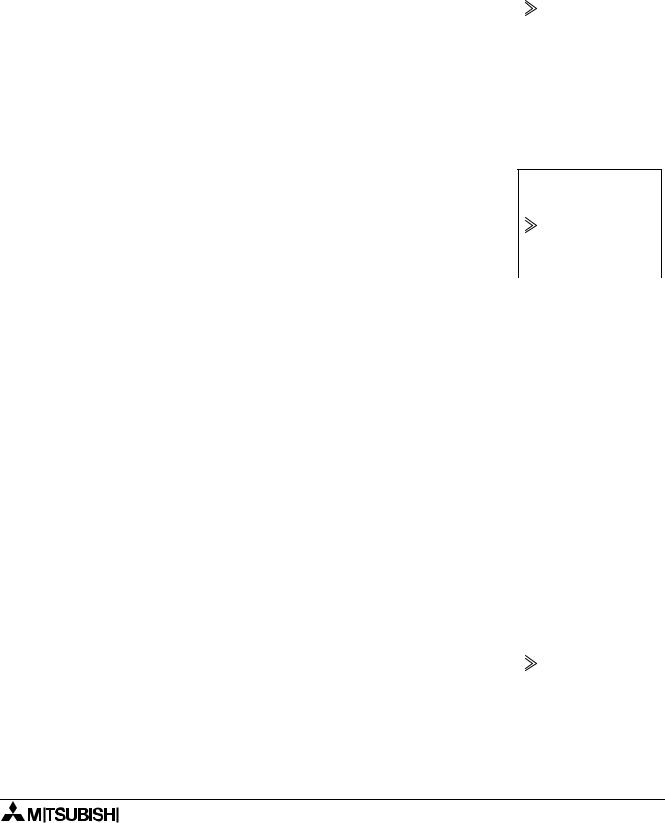
Move down to the Priority screen. The Priority can be set for either |
|
|
|
|
|
|
|
|
Time or Input. Move to the Time input and accept with the OK key. |
|
|
All the screen data has been set. Return to the Fbd board by using |
B 0 1 : O S |
|
the ESC key. |
P r i o r i t y |
|
|
T i m e |
|
|
I n p u t |
|
|
|
|
7 - 5

α Simple Application Controllers |
Lets Make a Program 7 |
|
|
7.5Exit the Function Block Diagram board
The programming is complete. To exit the Fbd, press the ESC key to bring up the Edit Menu. Scroll to the Exit option and enter OK to move to the Stop Mode Menu.
7 - 6

α Simple Application Controllers |
Lets Make a Program 7 |
|
|
7 - 7

α Simple Application Controllers |
Lets Make a Program 7 |
|
|
7 - 8

α Simple Application Controllers
Under no circumstances will MITSUBISHI ELECTRIC be liable or responsible for any consequential damage that may arise as a result of the installation or use of this equipment.
All examples and diagrams shown in this manual are intended only as an aid to understanding the text, not to guarantee operation. MITSUBISHI ELECTRIC will accept no responsibility for actual use of the product based on these illustrative examples.
Owing to the very great variety in possible application of this equipment, you must satisfy yourself as to its suitability for your specific application.

HEAD OFFICE: MITSUBISHI DENKI BLDG MARUNOUCHI TOKYO 100-8310 TELEX:J24532 CABLE MELCO TOKYO HIMEJI WORKS: 840, CHIYODA CHO, HIMEJI, JAPAN
JY992D76601C |
Effective Oct 1999 |
(MEE 9910) |
Specifications are subject |
|
to change without notice. |