

схемотехника / Manuals_Handb№cher / ALPHA / English / Alpha_Programming_Manual_versC_ENGLISH
.pdfα Simple Application Controllers |
Keys, Menus, and LCD Displays 3 |
|
|
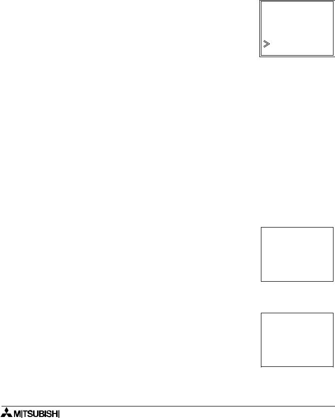
3.4The Run Mode Top Menu
When the Alpha program is running, the LCD defaults to the Image Table screen. Press any key (that is not an input key in the program) to view the Run Mode of the Top Menu.
•Stop: Takes the Alpha out of Run Mode.
•Monitor:
Monitor the program settings while in the Run mode. Function Block setups can be modified and new Inputs, FBs, and Outputs added to the program. The existing Run program cannot be modified in Monitor.
T o p M e n u
S t o p
M o n i t o r  C l o c k S e t
L A N G U A G E O t h e r s . . .
•Clock Set (see Stop Mode)
•LANGUAGE (see Stop Mode)
•Others (see Stop Mode):
Version, Password, Menu Key, Summertime, ModemInit (the Cassette option will not show).
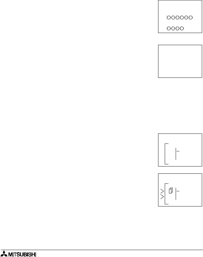
3.5The Edit Menu
The Edit Menu can be entered when the Alpha is in the ProgEdit or |
|
|
Monitor main programming screen. If entering options or connecting |
E d i t M e n u |
|
FBs, these procedures have to be finished or canceled before the |
P r o g S i z e |
|
Edit Menu can be entered. Press the ESC key at any time place in |
J u m p |
|
N e w F B |
||
the main programming screen to enter the Edit Menu. |
||
E x i t |
||
|
||
• ProgSize: |
M n e m o n i c |
Shows the numbers of FBs used and percent program memory used (64 function blocks or 1500 bytes or memory maximum).
Please refer to section 4.9 for the number of bytes used by each function block.
•Jump:
Leads to a screen that shows available places to go in the program. M - system bits (1-5); I - system Inputs (4, 6, or 12); O - system Outputs (2, 4, or 8), K - Keys (1-8); and B - Function Blocks (created by user). Choose the desired block with the arrow keys and enter OK to jump to that spot in the program.
•New FB:
Create a new Function Block from one of the 22 premade FBs. Refer to section 4.4 for details.
•Exit: Exits to the Top Menu.
•Mnemonic:
Gives a mnemonic display of the current programming rung. Enter the programming mode by OK or return to the Edit Menu by ESC.
3.6The Function Block Edit Menu
The Function Block Edit Menu can be entered only while in the ProgEdit or Monitor mode. Move to the Function Block to Edit and press OK when the Function Block number is flashing.
•Setup FB:
Optimize variables in the Function Blocks for your application. See Chapter 6 for more details on each Function Block’s Options. The logic functions in Chapter 5 do not have Setup Options.
•Change No.: Change the Function Block Number
•Delete FB: Delete Selected Function Block
B 0 4 : F L
S e t |
u p F B |
|
C h a n g e |
N o |
|
D e l |
e t e |
F B |
3 - 3
α Simple Application Controllers |
Keys, Menus, and LCD Displays 3 |
|
|
3.7Option Screen Setup
Various options have been provided for ease of use around the world or for safety purposes. Please set as your needs require. All of the options in this section can be accessed from either the Run or the Stop Menu.
3.7.1How to change the Language
Turn the Alpha On, hit the OK button to go to the Stop Menu. Scroll to the “LANGUAGE” option and enter OK. The spelling for “LAN-
GUAGE” does not change no matter the language chosen. Only four lines of text can appear on the screen so that the  and
and  arrows can be used to see all the languages. From Top to Bottom,
the languages available are Japanese, English, German, French,
Italian, and Spanish. Choose the appropriate language and enter OK. Use the Esc key to exit.
Note: Only four lines of text can appear on the screen at one time so the box will not appear as shown in the picture.
3.7.2 Real Time Clock SET
From either of the Top Menus, scroll to the ClockSet option and enter |
|
|
|
|
|
OK. Use the arrow keys to move to the various options and the “+” |
|
|
and “-” keys to manipulate the data. Update every option on the |
C l o c k |
S e t |
screen and then the entire screen can be accepted with the OK |
y y y y / m m / d d |
|
button. |
1 9 9 8 / 0 |
9 / 3 0 |
The first option is the setup of the Year, Month, Day menu. Options |
1 4 : 3 5 |
w e d |
include setting yyyy/mm/dd, dd/mm/yyyy, or mm/dd/yyyy. |
|
|
|
|
|
Now set the year, month, day, hour (24 hour clock) and minute. The |
|
|
day of the week will update automatically. |
|
|
Hit Esc to Cancel or OK to accept. |
|
|
3.7.3SummerTime
The Summertime menu will display six choices when entered. Cancel - Turns off the Summertime clock setting.
Manual On - Moves the clock one hour ahead immediately. Date Type - Set the On date, Off date, and Time adjustment.
UK Type - Last Sunday of March to the First Sunday of November. US Type - First Sunday of April to the last Sunday of October.
EU Type - Last Sunday of March to fourth Sunday of October.
S u m m e r T i m e C a n c e l
M a n u a l O n D a t e T y p e  U K T y p e
U S T y p e E U T y p e
3.7.4Password
The password consists of four digits and will prohibit entry into the ProgEdit and Monitor modes only. Run, Stop, ProgClear, etc. can still be accessed. When ProgEdit or Monitor is entered, a box will pop up onscreen asking for the password. If the password is entered correctly, the Monitor ProgEdit modes can be accessed.
When “Password” is first entered, “Setup” will appear in the top left corner of the screen. Enter the desired password and accept with OK. To cancel the code, enter “Password” and re-enter the secret code. “Cancel” will appear in the top left corner.
S e t u p
P a s s w o r d
0 9 2 1
3 - 4

α Simple Application Controllers |
Keys, Menus, and LCD Displays 3 |
|
|
3.7.5Modem Function
The modem function capability of the Alpha allows remote monitoring via a PC and program upload/download. The communication
must take place using the Visual Logic Software (VLS) and the communication must be initiated from there. (The α modem is initialized upon start up and cannot be set to dial out by an internal command or compare function).
Command - Input the AT command for the modem to be connected to the α controller. Choose the first letter or symbol by using the ( ) and (
 ) arrows. When the symbol is showing in the command line, use the (
 ) and (
 ) arrows to move to adjoining spaces. Enter up to 64 letters/symbols and accept the whole string with the OK button when finished inputting the data. (There is no need to accept each letter with the OK button).
M o d e m I n i t
 C o m m a n d D e l a y T i m e
M o d e m I n i 0 1 |
|
C o m m a n d |
|
[ |
] |
y z { |
} ! " # $ |
Delay - The Delay function sets the length of time the α will wait after entering the Run mode before turning on the modem. Choose a value of 0 - 10 seconds with the “+” or “-” keys. The modem connected to the Personal Computer with the VLS software must be On prior to the α modem turning on.
Please see the α Software Manual for instructions on setting up the VLS modem and/or the α modem parameters.
Hint: The α modem parameters can be set using the VLS software and downloaded to the controller.
3.7.6Memory cassette
Install the memory cassette prior to turning the α power On. The program contained in the cassette will be the active program to Run or Edit. A program contained in the α controller memory will not be
affected unless written to in the ProgTran. command. The line shown at right with the pointer is for transferring programs
from the Memory Cassette to the α controller memory.
The second Cassette option is to transfer the contents of the α controller memory to the memory cassette.
If the ProtectSW option is On, the memory cassette program cannot be edited.
If working with a memory cassette installed, the ProgClear will clear the program in the memory cassette but not the previous α controller program.
The Cassette cannot be used to add extra memory to an Alpha program. A memory cassette can be used with as many controllers as desired.
3 - 5
α Simple Application Controllers |
Keys, Menus, and LCD Displays 3 |
|
|
3.8LCD Displays
There are a number of types of data and/or information that can be displayed on the LCD display besides the menus listed above.
3.8.1 Image Table
The first LCD display to appear is the Input/Output image table and |
|
the Real Time Clock. |
|
An open circle indicates that a contact is Off. |
- - : - - |
A darkened circle indicates a contact is On. |
I : |
The clock shows the current time as Set by the User. The Summer- |
|
time mode is shown by an “s” preceding the time if activated. |
O : |
3.8.2LCD Function
Display up to 10 different letters or characters on each of four lines. Options include character strings (design your own message), function block data, or analog data.
W a t e r P u m p I s
O n
3.9Block Items
Each block item has an individual diagram that shows the block number, available number of input pins, the output pin if applicable, and the block mnemonic. Connections between blocks can be viewed at the pin locations when connected blocks are shown individually on the LCD. See examples below.
3.9.1Input Blocks
The Input Blocks consist of System Inputs (I01 - I12), Key Inputs (K01-K08), and System Bits (M01-M05). The input number is shown in the top right hand corner, the type of input in the lower right hand corner, and the output pin is shown on the far right of the block. Input Blocks provide information to the Function Blocks or Outputs.
3.9.2Function Blocks
The individual Function Blocks are described in detail in Chapters 5 and 6. Function Blocks can have from 0 to 4 input pins shown on the left of the diagram and an output shown on the far right. Some function blocks have data that can be used for comparison purposes only or are used to display data onscreen. These blocks have no output pin. The number and block mnemonic are shown in the top right and bottom right locations respectively.
0 1
I n
0 0
C N
3 - 6

α Simple Application Controllers |
Keys, Menus, and LCD Displays 3 |
|
|
3.9.3Output Blocks
Output Blocks have one input an done output pin. They only have the capacity for one input signal through the input pin. The Output Block number and Mnemonic are shown in the top right and lower right hand corner of the diagram respectively.
3.9.4Connected Blocks
Blocks that are connected can be shown simultaneously onscreen. The block providing the output signal will be shown on the left of the screen. The input pin accepting the signal will flash. Any input pin that is already connected will be shown as a solid triangle.
0 1
O u t
|
|
|
|
|
|
|
|
|
|
|
|
|
|
|
|
0 4 |
|
2 9 |
|
|
|
|
|||||||
|
|
|
|
|
|
|
|
|
|
|
|
|
|
|
|
|
|
|
|
|
|
|
|
|
|
|
|
|
|
|
|
|
|
|
|
|
|
|
|
|
|
|
||
|
|
I n |
|
|
|
|
C N |
|
|
|
|
|||
|
|
|
|
|||||||||||
|
|
|
|
|
|
|
|
|
|
|
|
|
|
|
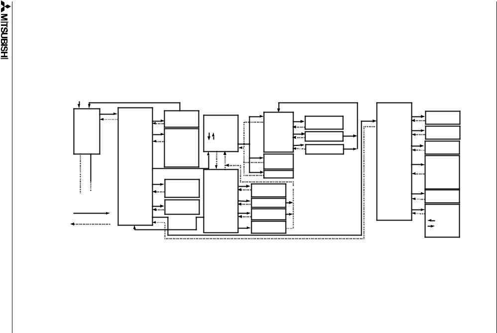
3.10Function Block Diagrams
The programming technique for Alpha begins by making a function block diagram. This is a pictorial representation of the information flow. The Inputs appear on the left side of the screen, the Function Blocks in the middle, and the Outputs on the Right hand side - the same style as in an actual the program.
Ex - In order to keep a light on for 20 seconds after the light switch has been turned Off (maybe there is a light switch at only one end of the hallway!), the following diagram has been drawn.
I 0 1 |
|
D E L A Y |
|
O 0 1 |
|
( 2 0 s e c ) |
|
||
|
|
|
|
|
|
|
|
|
|
There are three rectangles in the diagram:
1)Input I01 to receive the information that the light switch is Off.
2)A Delay Function Block to add the twenty second delay.
3)Output O01 to turn the light Off at the proper time.
Block diagrams are made only as an aid to inputting the program into the controller. The visual reference can be useful when checking to see that your connections have been properly constructed. The Visual Logic Software can show all the Function Block connections on your computer screen.
3 - 7
Power ON |
|
|
|
|
|
|
|
All key |
Top Menu |
|
|
|
|
Others |
|
Date |
STOP/RUN |
|
(FB Edit) |
|
|
Soft Version |
|
|
|
FB Parameter |
Version |
||||
Time,Day |
Run |
Confirmation |
FB Program |
Setup FB |
Display |
||
|
|
|
display |
OK:enter |
|
Password |
|
|
|
Language |
|
|
Password |
||
Input/ |
|
|
|
|
|||
Language |
|
Change.. |
FB..Change |
Set/Delete |
|||
German |
|
|
|||||
Output |
|
Delete |
|
|
Menu Key |
||
|
English |
FB Choice |
|
|
|||
|
|
|
|
||||
|
|
FB |
FB Delete |
Menu key |
|||
|
|
French |
|
Setting |
|||
|
|
|
(+)* |
|
|
||
|
|
Italian |
|
|
|
|
|
|
|
|
Connect |
|
|
Summer time |
|
|
|
Spanish |
|
(New FB) |
* When wire is |
|
|
|
|
|
SummerTim |
Cancel |
|||
|
ProgEdit |
|
|
||||
|
|
Edit Menu |
(-)* |
flashing |
Manual On |
||
|
|
|
Disconnect |
|
|||
|
|
All Program |
ProgSize |
|
|
|
Date type |
|
|
|
ProgramSize |
|
|
UK, US, EU |
|
|
|
delete |
|
|
|
||
|
ProgClear |
Jump |
|
|
Modem Initial |
||
See next page |
Confirmation |
display |
|
Modeminit |
|||
|
|
||||||
|
|
Timer |
New FB |
FB choice |
|
|
Code set |
|
ClockSet |
|
|
|
|||
|
|
|
|
Prog Transit |
|||
OK |
|
setting |
|
|
|
|
|
|
Exit |
Add New FB |
|
Prog Tran** |
Verify |
||
|
Others |
|
|
||||
ESC or OK/ESC |
|
|
|
Cassette |
|||
|
|
Mnemonic |
|
** Only when the memory |
|||
|
|
|
|
||||
|
|
|
Mnemonic |
|
Cassette |
||
|
|
|
Display |
|
cassette is installed prior |
||
|
|
|
|
ProtectSW |
|||
|
|
|
|
|
|||
|
|
|
|
|
|
to power On. |
|
|
|
|
|
|
|
|
8 - 3
Flow Instruction 11.3 |
Controllers Application Simple α |
Chart |
|
3 Displays LCD and Menus, Keys,

From |
Top Menu |
STOP/RUN |
|
|
|
Others |
|
|
(FB Edit) |
|
|||
previous |
|
FB Program |
|
|
||
Stop |
Confirmation |
FB Parameter |
Version |
|||
page |
|
|
display |
Setup FB |
||
|
Language |
OK:enter |
|
|||
|
|
|
|
|||
|
Language |
|
|
|
Password |
|
|
German |
|
Change.. |
FB..Change |
||
|
|
English |
FB Choice |
|
||
|
|
|
|
|
||
|
|
French |
|
|
|
Menu key |
|
|
Italian |
|
|
|
|
|
|
|
|
|
|
|
|
|
Spanish |
|
|
|
|
|
Monitor |
|
|
|
|
SummerTim |
|
|
|
Edit Menu |
ProgramSize |
|
|
|
|
Timer |
|
|
||
|
ClockSet |
ProgSize |
|
|
||
|
display |
|
|
|||
|
|
setting |
|
|
|
|
|
|
|
|
|
|
|
|
Others |
|
Jump |
FB choice |
|
|
|
|
|
|
|
Modeminit |
|
|
|
|
Exit |
|
|
|
|
|
|
|
|
|
9 - 3
Controllers Application Simple α
Soft Version |
Display |
Password |
Set/Delete |
Menu Key |
Setting |
Summer time |
Cancel |
Manual On |
Date type |
UK, US, EU |
Modem Initial |
Code set |
3 Displays LCD and Menus, Keys,

α Simple Application Controllers |
Keys, Menus, and LCD Displays 3 |
|
|
3 - 10

α Simple Application Controllers |
Direct Programming 4 |
|
|
4.Direct Programming
The Alpha can be programmed using only the keys on the front panel. When the function block diagram is complete, the program can be logically entered into the Alpha. The following sections will describe how to connect/disconnect function blocks, set program parameters, add Function Blocks, and move around within the program.
The ProgEdit mode in the Stop Menu has full programming capability. The Monitor mode in the Run Menu has the capability to manipulate Function Block values and settings but cannot edit, change, or delete the existing program.
4.1Block Availability
The number of System Inputs and Outputs is determined by the type of controller being programmed. Configurations include 4 In / 2 Out, 6 In / 4 Out, and 12 In / 8 Out.
Up to 64 Function Blocks can be used in a program or 1500 bytes of memory. The Function Blocks must be added in the course of programming. The eight Keys and the five system M bits are automatically available for every program.
Inputs, Outputs, System Memory Bits, and Keys do not count in the Function Block total.
4.2Connecting Blocks
Any block that has an output pin can be connected to any block that has an (unused) input pin. System Inputs, Keys, and Memory M bits have output pins only.
Function Blocks and Outputs have both input and output pins (the Display and TimeSwitch Blocks are exceptions). Blocks can be connected beginning with an output pin, from “left to right” on the display, or beginning with an input pin, from “right to left” on the display.
4.2.1To connect the blocks from the left (signal provider) block to right (signal receiver) block.
It is necessary to choose the block to provide the output (step 1), the block to accept the signal (step 2), and the pin with which to accept the signal (step 3).
1 ) Step 1: Select the block providing the data to be output and move to the right until the output pin is flashing. Press the “+”
button to “add” a block. 0 4
I n
2 ) Step 2: Choices will appear on the right side of the screen that include System Outputs (if available), existing Function Blocks that have free input pins, and the option to add a new function block (AddFB, see section 4.4). Scroll to the preferred option and select with the OK button.
0 4
A d d F B O 0 3
C o n n e c t
4 - 1
α Simple Application Controllers |
Direct Programming 4 |
|
|
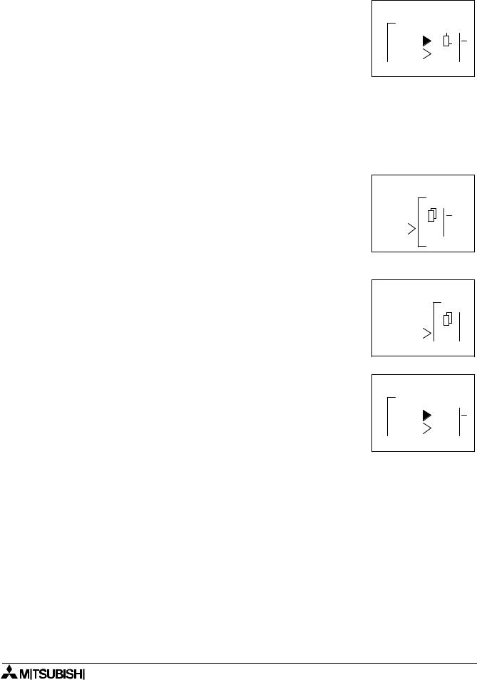
3 ) Step 3: The block accepting the signal will display as many of its input pins as possible (at times they will not all fit onscreen). Pins that have been used will show as filled triangles; pins that are open will show as “>” signs. A “Connect” prompt will appear onscreen, either above or below the left hand block. The current input choice will flash. Scroll to the desired pin and press OK to accept. The process is complete.
0 4 |
|
|
0 5 |
||||
|
|
|
|
|
|
|
|
|
|
|
|
|
|
|
|
|
|
|
|
|
|
|
|
C o n n e c t
4.2.2To connect the blocks from the right (signal receiver) block to left (signal provider) block.
It is necessary to choose the block input pin (Step 1), the signal provider (Step 2), and to accept the connection (Step 3).
1 ) Step 1: Select the block that will be receiving the signal and move left until an input pin is flashing. Scroll to the desired unused input pin (“>”). Enter “+” to begin the connection process.
2 ) Step 2: Because output pins may have multiple connections, all the Keys, Function Blocks, System Inputs, Outputs will show on the left of the screen as well as an option to “AddFB”. Scroll to the preferred option and Enter OK.
0 5
I 0 4
C N
0 5
A d d F B - I
M 0 1
C o n n e c t
3 ) Step 3: The chosen connection will be flashing onscreen along with the “Connect” prompt. Press OK to accept.
0 2 |
|
|
0 5 |
|
|
|
|
C o n n e c t
4.3Disconnect Two Blocks
Blocks can be disconnected by implementing the following procedure.
Move to the connection that is to be disconnected. Enter “-” as the disconnect command. A “Disconnect” prompt will appear onscreen. Press OK to accept the disconnect.
4 - 2