

4 Program Structure And Layout
4.1 Modular Programming In C51
This is possibly not the place to make the case for modular programming, but a brief justification might be appropriate.
In anything but the most trivial programs the overall job of the software is composed of smaller tasks, all of which must be identified before coding can begin. As an electronic system is composed of several modules, each with a unique function, so a software system is built from a number of discrete tasks. In the electronic case, each module is designed and perfected individually and then finally assembled into a complete working machine. With software, the tasks are the building blocks which are brought together to achieve the final objective.
The overall program thus has a loosely-predefined modular structure which could sensibly form the basis of the final software layout. The largest identifiable blocks within the program are the tasks. These are in turn built from modules, which themselves are constructed from functions in the case of C.
The modules are in reality individual source files, created with a text editor. Grouping the software sections together according to the function with which they are associated is the basis of modular programming.
Using the CEMS engine control system again as a real example, the task of running the engine is divided into the following tasks:
Task 1
Provide Timed Sparks For Ignition
Task 2
Provide controlled pulsewidths for fuel injection
Task 3
Allow alteration of tune parameters via terminal
Considering Task 1, this is in turn composed of modules thus:
Task 1, Module 1
Determine crank shaft position and speed
Task 1, Module 2
Measure engine load
Task 1, Module 3
Obtain required firing angle from look-up table
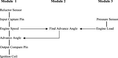
Taking module 2, a C function exists which uses an A/D converter to read a voltage from a sensor. It is part of the overall background loop and hence runs in a fixed sequence. In module 1 an interrupt function attached to an input capture pin calculates engine speed and generates the ignition coil firing pulse. Module 3 is another function in the background loop and takes speed and load information from the other modules constituting the ignition function, to calculate the firing angle. Obviously, data must be communicated from the data collecting functions to the processing functions and thence to the signal generation parts across module boundaries.
In this case, the data flows are thus:
© Copyright Hitex (UK) Ltd. 1996 |
C51 Primer page 19 |
Commonly, the variables used are declared in the module that first supplies them with data. Hence the engine_load would be defined in Module 2 as that is where its input data comes from.
In this system the data would be declared thus:
Module_1.c
/* Global Data Declaration */
unsigned char engine_speed
/* External Data References */
extern unsigned char advance
Module_3.c
/* Global Data Declaration */
unsigned char advance
/* External Data References */
extern unsigned char engine_speed
Module_2.c
/* Global Data Declaration */
unsigned char engine_load
/* External Data References */
extern unsigned char engine_load
The most important thing to note is how the data defined in another module is referenced by redeclaring the required data item but prefixed with “extern”.
Now, with a complete program spread across many different source files, the problem arises of how data is communicated between modules (files) and how separate C functions which lie outside of the home module may be accessed.
The next section illustrates how the linkage between modules is undertaken.
4.2 Accessibility Of Variables In Modular Programs
A typical C51 application will consist of possibly five functional blocks (modules) contained in five source files. Each block will contain a number of functions (subroutines) which operate on and use variables in RAM. Individual functions will (ideally) receive their input data via parameter passing and will return the results similarly. Within a function temporary variables will be used to store intermediate calculation values. As used to be done years ago in assembler, all variables (even the temporary ones) will be defined in one place and will remain accessible to every routine.
This approach is very inefficient and would seriously limit the power of C programs, as the internal RAM would soon be used up. The high-level language feature of a clearly defined input and output to each function would also be lost. Similarly, an entire C program might be written within one single source file. As has been said, this practice was common many years ago with simple assemblers. Ultimately the source program can get so big that the 640K of a PC will get full and the compiler will stop. Worse than this, the ideal of breaking programs into small, understandable chunks is lost. Programs then become a monolithic block and consume huge amounts of listing paper...
There should therefore be a hierarchical arrangement of variables and functions within a program; complete functional blocks should be identified and given their own individual source files or modules. Use should be made of the ability to access external variables and functions to achieve small program files!
The following should help explain:
MODULE1.c: **************************************************************
unsigned |
char global1 ; |
(1) |
||
unsigned char global2 ; |
|
|||
extern unsigned char ext_function(unsigned char) ;(2) |
||||
/* Utility Routine */ |
|
|
||
int_function(x) |
(3) |
|
||
unsigned char x ; |
(4) |
|
||
{ |
|
|
|
|
unsigned int temp1 |
; |
(5) |
||
unsigned char temp2 ; |
|
|||
temp 1 = x * x ; |
|
|
||
temp2 |
= x + x ; |
|
|
|
x = temp1/temp2 ; |
|
|
||
return(x) |
(6) |
|
|
|
} |
|
|
|
|
/* Program Proper */ |
|
|
||
main() |
(7) |
|
|
|
{ |
|
|
|
|
unsigned char local1 ; |
(5) |
|||
© Copyright Hitex (UK) Ltd. 1996 |
C51 Primer page 20 |
unsigned |
char local2 ; |
|
|
local2 |
= |
int_function(local1) ; |
(8) |
local1 |
= |
ext_function(local2) ; |
(9) |
}
end of MODULE1.c **************************************************************
MODULE2.c: **************************************************************
extern unsigned char global1 ; (10)
ext_function(y) unsigned char y ;
{
unsigned char temp ;
static unsigned char special ; (11)
special++ ;
y = temp * global1 ; (12)
return(y) ;
)
Line (1) declares variables which will be accessible from all parts of the program. Ideally, such global usage should be avoided but where an interrupt has to update a value used by the background program, for example, they are essential.
Line (2) makes an external reference to a function not defined in the current module (block). This line allows all the functions in this MODULE to call the external function.
Line (3) declares a function which is to be used by another function in this module. These utility functions are placed above the calling function (here “main()”).
Line (4) declares the variable which has been passed-over by the calling function. When the variable left “main()”, it was called “local1”. Within this function it is known simply as “x”. The byte of ram is allocated to “x” only while the 8051’s program counter is within this function. At the closing }, x will vanish.
Line (5) like “x” above, these variables are simply used as intermediate values within the function. They have no significance outside. Again, the byte of RAM will be re-assigned within another function. However the locals defined in “main()” will always exist as the C program is entirely contained within “main()”.
Line (6) allows the result of the calculation to be passed back to the calling function. Once back in “main()” the value is placed in “local2”.
Line (7) defines the start of the C program. Immediately prior to the point at which the program counter reachs main(), the assembler routine “STARTUP.A51” will have been executed. This in turn starts at location C:0000, the reset vector. Note that no parameters are passed to “main()”.
Line (8) effectively calls the function defined above, passing the value “local1” to it.
Line (9) is like 8, but this time a function is being called which resides outside of the current module.
Line(10) links up with line(1) in that it makes “global1” visible to function within MODULE 2.
Line(11) declares a variable which is local to this function but which must not be destroyed having exited. Thus it behaves like a global except that no other function can use it. If it were placed above the function, accessibility would be extended to all functions in MODULE 2.
The physical linking of the data names and function names between modules is performed by the L51 linker. This is covered in detail in section 8.
© Copyright Hitex (UK) Ltd. 1996 |
C51 Primer page 21 |
4.3 Building A Real Modular Program - The Practicalities Of Laying Out A C51 Program
The need for a modular approach to program construction has been outlined earlier. Here the practicalities of building easily maintainable and documentable software is given, along with a trick for easing the development of embedded C programs using popular compilers such as the Keil C51.
4.3.1 The Problem
The simplest embedded C program might consist of just:
/* Module Containing Serial Port Initialisation */ /* V24IN537.C */ void v24ini_537(void)
{
/* Serial Port Initialisation Code */
}
/* Module Containing Main Program */ /* MAIN.C */ /* External Definitions */
extern void v24ini_537(void) ;
void main(void) { v24ini_537() ; while(1) {
printf(“Time = “) ;
}
This minimal program has only one purpose - to print an as yet incomplete message on the terminal attached to the serial port. Obviously, a single source file or “module” is sufficient to hold the entire C program.
Any real program will of course contain more functionality than just this. The natural reaction is to simply add further code to the existing main function, followed by additional functions to the MAIN.C source file. Unless action is taken the program will consist of one enormous source file, containing dozens of functions and interrupts and maybe hundreds of public variables.
Whilst compilers will still compile the file, the compilation time can become greatly extended, meaning that even the smallest modification requires the entire program to be re-compiled. A monolithic program is usually symptomatic of a lack of proper program planning and is likely to contain suspect and difficult to maintain code.
The next stage in the sample program development is to add some means of generating the time thus:
/* Module Containing Timer0 Initialisation */ /* T0INI537.C */
void timer0_init_537(void) {
/* Enable Timer 0 Ext0 interrupts */ } /*init_timer_0*/
/* Module Containing Timer0 Service Routine */ /* RLT_INT.C */
/* Local Data Declarations */ /* Clock Structure Template */
struct time { unsigned char msec ; unsigned char sec ; } ;
/* Create XDATA Structure */
struct time xdata clock ;
bit clock_run_fl = 0 ; // Flag to tell timer0 interrupt // to stop clock
/* External References */
extern bit clock_reset_fl // Flag to tell timer0 interrupt to reset clock to zero
© Copyright Hitex (UK) Ltd. 1996 |
C51 Primer page 22 |