

15.7 Floating Point Numbers
One operand is always pushed onto an arithmetic stack in the internal RAM. In the SMALL model the 8051 stack is used, but in other models a fixed segment is created at the lowest available address above the register bank area. In applications where on-chip RAM is at a premium, full floating point maths really should not be used. Fixed point is a far more realistic alternative.
16 Conclusion
The foregoing should give a fair idea how the C51 compiler can be used in real embedded program development. Its great advantage is that it removes the necessity of being an expert in 8051 assembler to produce effective programs. Really, for the 8051, C51 should be viewed as a universal low to medium level language which both assembler and C programmers can move to very simply. Access to on and off-chip peripherals is painless and the need for assembler device-drivers is removed. It will allow well structured programs devoid of the dreaded “goto” or “LJMP”. In fact most of the extra code generated by C over an assembler is employed in ensuring good program structure rather than just inefficient use of the 8051 instruction set. It offers true portability from the 8051 to other processors and, unusually, the reverse is also true. Thus existing functions can be re-used, so reducing development time.
© Copyright Hitex (UK) Ltd. 1996 |
C51 Primer page 86 |
Appendix A
Constructing A Simple 8051 C Program
Often the most difficult stage in 8051 C programming is getting the first program to run! Even if you are not having to grapple with C as a new language, the business of dealing with special function registers, interrupts and memory-mapped peripherals can be a bit daunting.
This simple program contains all the basic steps required to get an 8051 program to run. Like all the classic first programs, it prints “hello world” down the serial port which is assumed to be connected to a dumb terminal.
A First C51 Program
/**************************************************************************** * Main Program - Simplest Version *
****************************************************************************/
/* This program is entered from the reset vector. It simply initialises the serial port, and prints “hello world” repeatedly */
/* Declare Memory Model */
.i.#pragma;#pragma SMALL // Set SMALL model (on-chip RAM only)
#include “\C51P\INC\stdio.h” // Include file contains function prototype for printf. /* Function Prototype */
void serial0_init_T1(void) ; // Serial port initialisation function
/* Main Loop */ |
|
void main(void) |
// Enter from reset vector |
{ |
|
serial0_init_T1() ; |
// Initialise serial port 0 timer1 baudrate generator |
/*** Loop Forever ***/ |
|
while(FOREVER) { |
|
printf(“hello world”) ; // Send message down 8051 serial port forever
}
}
/************************************************************************** This function initialises Serial Port 0 to run at
4800 Baud using the Timer 1 auto-reload mode with a 12MHz XTAL.
**************************************************************************/
/* To get 9600 baud with timer1 requires an 11.059MHz crystal! */
void serial0_init_T1(void)
{
TH1 = 0x0f3 |
; |
/* Timer 1 high byte (= reload value) SMOD = 0, F(Osc) = 12 MHz, |
|
|
and Timer 1 in mode 2, baudrate of 4800 Baud Timer 1 Interrupt is |
|
|
disabled after RESET */ |
TMOD |= 0x20 |
; |
/* Load Timer Mode Control Register Timer 1 under software |
|
|
control with TR1 as Timer in mode 2(= 8 bit, auto-reload) */ |
S0CON = 0x52 |
; |
/* Serial connection in mode 1 (= 1 Start-,8 Data-, 1 stop |
|
|
bit)start enabled Transmitter empty, Receiver empty */ |
PCON |= 0x80 |
; |
/* SMOD = 1 to double baud rate */ |
TR1 = 1 |
; |
/* Timer 1 start */ |
} |
|
|
© Copyright Hitex (UK) Ltd. 1996 |
C51 Primer page 87 |
This should be placed in a module, preferably called “main.c” and compiled with:
>C51 main.c
This produces a file, ‘main.obj’
Next, link main.obj with the printf function, held in a C51S.LIB library, and fix the location of the program:
>L51 main.obj,\c51p\lib\c51s.lib to exec.abs
To yield an Intel OMF51 format file named “exec.abs”. If you are using an EPROM programmer, you will need an Intel HEXfile.
Use OHS51.EXE for this:
>OHS51 exec.abs
to give exec.hex an Intel HEX file.
Basically this is all there is to producing a working C51 program! Some refinements might be to make sure that the C51LIB DOS environment variable has been set to indicate where the C51S.LIB is located.
To do this, make sure that you have
SET C51LIB=\C51P\LIB
in your autoexec.bat file.
Likewise, if you also add
SET C51INC=\C51P\INC,
the long and untidy pathname for ‘stdio.h’ can be eliminated.
If C51 has been installed properly, this should have already been done.
Appendix B
Driving The 8051 For Real
The following example program does the following typical 8051 tasks:
(i)Read a port pin value
(ii)Write a port pin value
(iii)Generate a periodic timer interrupt
(iv)Transmit data via the serial port
(v)Write to a memory-mapped port
It is suggested that to get started you steal sections from the following program! Although the Infineon 80C537 has been used as the basis for this, the approaches used are applicable to all 8051 variants.
#include <stdio.h> |
/* |
include standard io libs |
|
*/ |
||
#include <reg517.h> |
/* |
include 80C517 register set |
*/ |
|||
#include |
<math.h> |
/* |
include |
mathematical prototypes |
*/ |
|
#include |
<string.h> |
/* |
include |
string handling |
functions */ |
|
#pragma |
MOD517 |
/* |
Use 80C537 extensions |
*/ |
|
|
© Copyright Hitex (UK) Ltd. 1996 |
C51 Primer page 88 |
The 8051 areas covered are:
1.Serial Port0 - Polled Mode
-Baudrate generation from timer1
-Baudrate generation from baudrate generator
2.Analog To Digital Convertor
-Reading values into an array
3.Frequency Measurement
-Input Capture CC0
4.Time Pulse Generation
-Output compare CC4
5.Symmetrical PWM Generation
-CC3 and timer2 overflow
6.Zero CPU Overhead Asymmetric PWM Generation
-CMx/Compare Timer
7.Accessing Memory-Mapped Ports
-Via pointers
-With XBYTE[]
**************************************************************************
* Global Definitions *
**************************************************************************/
/*** CCMx PWMS ***/
xdata float pwm_period = 42.5 ; // Initial period in us,variable located in XDATA.
xdata float pwm_duty_ratio = 50 ; // Initial ratio in % xdata unsigned int pwm_prescale = 0 ;
/*** Analog Inputs ***/
xdata float analog_data[4]; // Floating point array xdata unsigned char rx_byte;
xdata unsigned char channel_0 = 0 ; xdata unsigned char channel_1 = 0 ;
/*** Timer0 Overflow Timebase ***/
xdata unsigned int real_time_count = 0 ;
/*** Timed Pulse Generation ***/
xdata unsigned char marker_angle = 128 ;
data unsigned |
int marker_time = 0 ; |
|||
unsigned int time_for_360 = 0 ; |
||||
unsigned int time_last_360 = 0 ; |
||||
xdata |
unsigned int frequency = 0 ; |
|||
xdata |
unsigned int analog_data10 = 0 ; |
|||
/*** Port |
1 Bit |
Definitions ***/ |
||
sbit |
P10 |
= |
0x90; |
// CC0 |
sbit |
P13 |
= |
0x93; |
// CC3 |
sbit |
P14 |
= |
0x94; |
// CC3 |
/*** Symmetrical PWM Generation ***/
© Copyright Hitex (UK) Ltd. 1996 |
C51 Primer page 89 |
xdata unsigned int symm_PWM_DR = 256 ; // Integer ratio from background xdata unsigned int symm_PWM_period = 2048 ; //PWM Period = 4096us
/
****************************************************************************
* General Definitions *
****************************************************************************/
#define FOREVER 1
/*** CMx PWM Control ***/
#define Pulse_Width |
25 |
/* 50us marker pulse */ |
|
#define PWM_Resolution |
0.1666667 |
/* Smallest PWM time is at 12MHz */ |
|
/*** Cursor Positioning Escape Codes For VT52 ***/ |
|
||
code char Line0[] = { 0x1b,’Y’,0x20,0x20,0 } ; |
|
||
code char Line1[] = { 0x1b,’Y’,0x21,0x20,0 } ; |
|
||
code char Line2[] = { 0x1b,’Y’,0x22,0x20,0 } ; |
|
||
code char Line3[] = { 0x1b,’Y’,0x23,0x20,0 } ; |
|
||
code char Line4[] = { 0x1b,’Y’,0x24,0x20,0 } ; |
|
||
code char Line5[] = { 0x1b,’Y’,0x25,0x20,0 } ; |
|
||
code char Line6[] = { 0x1b,’Y’,0x26,0x20,0 } ; |
|
||
code char Line7[] = { 0x1b,’Y’,0x27,0x20,0 } ; |
|
||
code char Line8[] = { 0x1b,’Y’,0x28,0x20,0 } ; |
|
||
code char Line9[] = { 0x1b,’Y’,0x29,0x20,0 } ; |
|
||
code char Line10[] = { 0x1b,’Y’,0x2a,0x20,0 } ; |
|
||
code char Line11[] = { 0x1b,’Y’,0x2b,0x20,0 } ; |
|
||
code char Line12[] = { 0x1b,’Y’,0x2c,0x20,0 } ; |
|
||
code char Line13[] = { 0x1b,’Y’,0x2d,0x20,0 } ; |
|
||
code char Line14[] = { 0x1b,’Y’,0x2e,0x20,0 } ; |
|
||
code char Line15[] = { 0x1b,’Y’,0x2f,0x20,0 } ; |
|
||
code char Clear[] = { 0x0C,0 } ; |
|
|
|
code char double_bell[] = { 0x07,0x07,0x07,0 } |
; |
||
/
**************************************************************************
* Function Prototypes *
**************************************************************************/
void ad_init(void); void serial_init(void);
void serial0_init_BD(void); void serial0_init_T1(void); void send_byte(unsigned char); void ad_convert(void);
void capture_init(void);
extern void control_pwm(void) ;
/
*****************************************************************************
* This function initialises the A/D convertor (P103 of 517 manual) *
*****************************************************************************/
void ad_init(void)
{
ADCON0 &= 0x80 ; // Clear register but preserve BD bit
ADCON0 |= 0x01 ; /* Single conversion internal Start Channel 0 */
}
/
*****************************************************************************
*This function will perform three conversions on the A/D convertor reading values from
channels 0 - 3 *
*****************************************************************************/
/* Channel 0 is read using the 10 bit programmable reference method */
void ad_convert(void)
{
unsigned char i;
for(i = 1 ; i < 4 ; i++)
© Copyright Hitex (UK) Ltd. 1996 |
C51 Primer page 90 |
{
ADCON0 &= 0x80 ; // Preserve BD bit (80C537 only)
ADCON0 |
|= i ; |
DAPR |
= 0 ; |
while (BSY) |
|
{ ; |
} |
analog_data[i] = ((float) ADDAT * 5) / 255 ;
}
}
*****************************************************************************
* These routines will transmit and receive single characters by Polled use of the serial Port 0
*
*****************************************************************************/
/* Note: In real applications, an interrupt-driven serial port is usually preferable to avoid loss of characters.*/
char receive_byte(void) |
/* Polled use of serial port */ |
|
{ |
|
|
if(RI == 1) /* Test for char received |
*/ |
|
{ |
|
|
rx_byte = S0BUF ; |
/* Place char in rx_byte */ |
|
RI = 0 ; |
/* clear flag |
*/ |
} |
|
|
else { |
|
|
rx_byte = 0 ; |
|
|
} |
|
|
return(rx_byte) ;
}
void send_byte(char tx_byte) /*Polled use of serial port*/
{
TI = 0; |
// |
Clear TI flag |
|
S0BUF = |
tx_byte ; // |
Begin transmission |
|
while (!TI) {;} |
// |
Wait until transmit flag is set |
|
}
/
**************************************************************************
*This function initialises Serial Port 0 to run at 9600 Baud using the Siemens Baud rate
generator (see P76 of the 517 Manual) *
**************************************************************************/
/* This method does not tie up timer1 as on ordinary 8051’s */ void serial0_init_BD(void)
{ |
|
|
|
|
|
BD |
= 1; |
/* |
Enable Baud rate generator |
*/ |
|
PCON |
= PCON | |
0x80; /* Set SMOD to double baud rate */ |
|||
S0CON = 0x50; |
|
/* Mode 1, Receiver enabled */ |
|||
TI |
= 1; |
/* |
Set Transmit interupt flag |
for first run through PRINTF */ |
|
}
/
**************************************************************************
* This function initialises Serial Port 0 to run at 4800 Baud using the Timer 1 auto-reload mode. *
**************************************************************************/
/* To get 9600 baud with timer1 requires an 11.059MHz crystal */
void serial0_init_T1(void)
{
TH1 = 0x0f3 ; /* Timer 1 high byte (= reload value) SMOD = 0,
F(Osc) = 12 MHz,and Timer 1 in mode 2,baudrate of 4800
Baud Timer 1 Interrupt is disabled after RESET */
TMOD |= 0x20 ; /* Load Timer Mode Control Register Timer 1 under software control with TR1 as Timer
© Copyright Hitex (UK) Ltd. 1996 |
C51 Primer page 91 |
in mode 2(= 8 bit, auto-reload) */
S0CON = 0x52 ; /* Serial connection in mode 1 (= 1 Start-, 8 Data-, 1 stop bit) start enabled Transmitter empty, Receiver empty */
PCON |= 0x80 ; /* SMOD = 1 to double baud rate */
TR1 = 1 ; /* Timer 1 start */
}
/
*****************************************************************************
* Generate 2ms Timer Tick On Timer 0 *
*****************************************************************************/
/* Entered |
every timer0 overflow */ |
|||
void timer0_init(void) |
|
|
||
{ |
|
|
|
|
TR0 = 0 |
|
; |
|
|
TMOD |= |
01 |
; |
/* 16 bit timer mode */ |
|
TH0 = 0xf8 |
; |
/* Reload with with count for 2ms time base at 12MHz */ |
||
TL0 = 0x82 |
; |
|
|
|
TR0 = 1 |
|
; |
/* |
Start timer */ |
IEN0 |= |
0x02 |
; |
/* |
Enable Timer 0 Ext0 interrupts */ |
} /*init_timer_0*/
/
*****************************************************************************
* Timer0 Interrupt Service Routine *
*****************************************************************************/
/* An allowance really needs to be made for the fact that the timer is stopped during the reinitialisation process */
/* “interrupt” arguments are:
‘1’ => generate interrupt vector at address 8*1 + 3 = 0x0b ‘2’ => Switch to register bank two on entry, restore
original bank on exit */
void timer0_int(void) interrupt 1 using 2
{
/* Setup Next Interrupt ***/
IEN0 &= 0xfd ; |
/* Clear interrupt flags */ |
|
TR0 = 0 |
; |
/* Stop timer */ |
TH0 = 0xf8 |
; |
/* Reset timer for next interrupt */ |
TL0 = 0x2f |
; |
/* 2ms at 12 MHZ */ |
TR0 = 1 |
; |
/* Start timer */ |
IEN0 |= 0x02 |
; |
|
real_time_count++ ; |
||
P6 ^= 0x08 |
; |
|
} |
|
|
/
*****************************************************************************
*This function sets up the Capture Compare Unit and generates a PWM output on Port 4.0 (Pin 1). See p112 of the 517 Manual *
*=> CTREL = 65536 - 255 for 42.5us period/ overflow rate at 12MHz *
*Compare timer counts from CTREL to 65535 when Port bit is cleared Port bit set when Compare timer = CM0 to give asymmetric 8 bit PWM *
*****************************************************************************/
/* This PWM requires no CPU time and is thus very efficient */
/* On 535 an interrupt service would be required to reload the compare */ /* register */
void pwm_init(void)
{
© Copyright Hitex (UK) Ltd. 1996 |
C51 Primer page 92 |
union { unsigned int temp ; unsigned char tmp[2] ; } t ;
CTCON = 0 ; // Basic count time = 166ns
t.temp = -pwm_period/PWM_Resolution ; // 42.5us
initial period
CTRELH = t.tmp[0] ;
CTRELL = t.tmp[1] ;
CM1 = t.temp + ((unsigned int)(65536 - t.temp) * pwm_duty_ratio)/100 ; // Initial duty ratio = 255:1
CM0 = CM1 ;
CMSEL = |
0 |
; |
|
|
CMSEL | |
= |
1 |
; // Assign CM0 to compare timer |
|
CMSEL | |
= |
2 |
; // Assign CM1 to compare timer |
|
CMEN = |
0 |
; |
|
|
CMEN | |
= |
1 |
; // Enable port 4.0 |
as PWM |
|
|
|
(front) |
|
CMEN | |
= |
2 |
; // Enable port 4.1 |
as PWM |
|
|
|
(rear) |
|
} |
|
|
|
|
/
*****************************************************************************
*This function initializes the Output Compare/Input Capture System on Timer2/Port 1. Two
captures are enabled: CC0 captures an event on Pin |
1.0, CC1 will be triggered by a write to the |
||||||
low order Byte CCL1 |
* |
|
|
||||
*****************************************************************************/ |
|||||||
/* The capcom unit when attached to timer2 is suitable for |
|||||||
frequency |
|
*/ |
|
|
|
|
|
/* measurement and pulse generation */ |
|
||||||
void capture_CC0_init(void) |
|
|
|||||
{ |
|
|
|
|
|
|
|
T2CON |
|
= |
0 |
|
; |
|
|
T2I1 |
= |
|
0 ; /* Timer 2 = 12MHz/24 = 2us/count */ |
|
|||
T2I0 |
= |
|
1 ; |
|
|
|
|
T2PS |
= |
|
1 ; /* /2 prescale for 2us/count */ |
|
|||
CTCON |
|
= |
0 ; |
|
|
|
|
T2CM |
= |
|
1 ; |
/* Timer 2 compare/capture in mode 1*/ |
|||
T2R1 |
= |
|
0 ; |
/* No autoreload off CC0 */ |
|
||
CCEN |
= |
|
0 ; |
|
|
|
|
CCEN |
|= 0x01 ; /* Input capture on CC0 */ |
|
|||||
CCEN |
|= 0x0C ; |
/* Timer 2 latched into CC1 on write |
|||||
|
|
|
|
|
into CCL1 */ |
|
|
CCEN |
|= 0x80 ; |
/* CC3 is output compare */ |
|
||||
I3FR |
= |
0 |
|
; |
/* CC0 is initially -ve edge |
|
|
|
|
|
|
|
triggered */ |
|
|
P1 | |
= |
0x01 |
; |
/* Put port 1.0 high for input |
|||
|
|
|
|
|
capture */ |
|
|
EX3 |
= |
1 |
|
; |
/* Enable |
capture interrupt for road |
|
|
|
|
|
|
speed |
*/ |
|
EX2 |
= |
1 |
|
; |
/* Enable output compare interrupt |
||
|
|
|
|
|
for ign0 */ |
|
|
CC4EN = |
0x05 |
; |
/* CC4 port 1.4 is output compare |
||||
|
|
|
|
|
mode 1 |
*/ |
|
IP0 |
= |
0 |
|
; /* Initialise interrupt priorities */ |
|||
IP1 |
= |
0 |
|
; |
|
|
|
© Copyright Hitex (UK) Ltd. 1996 |
C51 Primer page 93 |
IP1 |
|= |
0x26 ; |
/* Make CC4 interrupt |
3 priority */ |
IP0 |
|= |
0x3A ; |
/* Input capture is 2 |
priority */ |
} |
|
|
|
|
/
******************************************************************************
* Input Capture Interrupt On Port1.0/CC *
******************************************************************************/
/* On every negative edge at P1.0, this routine is entered*/ /* Frequency calculation is possible using:
frequency = 100000/(Timer2 Count Time * (this T2 - last timer2))
= 50000/(CRC - last CRC)
A new pulse is generated at a fixed angle after the interrupt using CC4 output compare
-This is the basis for ignition and injection timing in engine management systems
-The maths unit is essential for keeping run times short.
*/
void CC0_int(void) interrupt 10 using 3
{
unsigned int temp ;
/* Calculate Input Frequency */
frequency = 500000 /(unsigned long) (CRC - time_last_360) ;
time_for_360 = CRC - time_last_360 ;
temp = CRC + (unsigned int)
((unsigned long)((unsigned long)time_for_360 * marker_angle)/255) ;
EAL = 0 ; marker_time = temp ; EAL = 1 ;
time_last_360 = CRC ;
}
/
****************************************************************************
* Generate marker pulse after CC0 interrupt *
****************************************************************************/
/* Entered in response to request from CC0 interrupt to generate a pulse at a predefined time afterwards. */
void marker_int(void) interrupt 9 using 2
{
unsigned int timer_temp ;
EX2 = 0 ;
if(P14 == 0)
{
/* Port Pin Low */
if((int)(marker_time - CC4 - 500) > 0) { timer_temp = marker_time ;
}
else {
© Copyright Hitex (UK) Ltd. 1996 |
C51 Primer page 94 |
timer_temp = marker_time + time_for_360 ;
}
CC4 = timer_temp ;
IEX2 = 0 ;
P14 = 1 ; |
// Turn on at next compare |
EX2 = 1 |
; |
} |
|
else |
|
{ |
|
/* Port Pin High */
timer_temp = CC4 + Pulse_Width ; CC4 = timer_temp ;
IEX2 = 0 |
|
; |
P14 = 0 |
; |
// Turn off at next compare |
EX2 = 1 |
|
; |
} |
|
|
}
*****************************************************************************
*This function initialises the Output Compare/Input Capture System on Timer2/
*Port 1 to generate a symmetrical PWM on CC4. *
*****************************************************************************/
/* This gives a PWM output where the on-time grows from either side of the timer 2 overflow point */
/* This is very useful for motor control as the symmetrical nature of the waveform reduces the higher current harmonics circulating in the windings under changing duty ratio
conditions. */
/* Downside is that two interrupt services are required per period |
*/ |
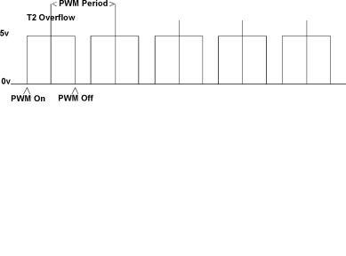
Symmetrical PWM Waveform
Asymmetrical PWM Waveform
© Copyright Hitex (UK) Ltd. 1996 |
C51 Primer page 95 |
void symm_PWM_init(void)
{ |
|
|
|
T2CON = 0 ; |
/* Clear configuration register |
*/ |
|
T2I1 = 0 |
; |
/* Timer 2 = 12MHz/24 = 2us/count */ |
|
T2I0 = 1 |
; |
|
|
T2PS = 1 |
; |
/* /2 prescale for 2us/count */ |
|
/* Additional prescale possible on BB step |
*/ |
||
T2CM = 1 |
; |
/* Timer 2 compare/capture in mode 1 */ |
|
T2R1 = 1 |
; |
/* Autoreload off CC0 */ |
|
T2R0 = 0 |
; |
/* mode 1 (CRC into Timer2 at rollover)*/ |
|
/* Set initial reload value (4096us/2048 steps) */
CRC = -2*symm_PWM_period ;
ET2 = 1 ; /* Enable timer2 overflow interrupt */
EX3 = 1 ; /*Enable capture interrupt for PWM drive*/
CCEN = 0 ; /* CRC - CC2 unused */
CCEN |= 0x80 ; /* CC3 is symmetrical PWM output */
IP0 = 0 ; /* Initialise interrupt priorities */
IP1 = 0 ;
IP1 |= 0x20 ; /* Make CC3/T2 Overflow interrupts priority 3 */
P10 = 0 ;
}
/**************************************************************************** * Timer 2 Overflow Interrupt *
****************************************************************************/
/* Interrupt at centre point of waveform to create next off point */
/* A good example of where C now givesoverhead when compared with assembler! */
/* USING gives single cycle registerbank switch like ‘166 */
void timer2_overflow(void) interrupt 5 using 2
{
/* Runtime here limits min/max PWM DR */
P1 |= 0x01 ; /* Toggle P1.0 to show centre of PWM */
TF2 = 0 ; /* Clear interrupt request flag */
CC3 = CRC + symm_PWM_DR ;
IEX6 = 0 ;
P13 = 0 ;
EX6 = 1 ;
P1 &= 0xfe ; /* Toggle P1.0 to show centre of PWM */
}
/**************************************************************************** * CC4 Interrupt For Symmetrical PWM *
****************************************************************************/
/* Interrupt at end of first on period of waveform to create next on point */
void symm_PWM_CC3_int(void) interrupt 13 using 2
{
/* Runtime here limits min/max PWM DR */
CC3 = -symm_PWM_DR ;
IEX6 = 0 ;
P13 = 1 ;
© Copyright Hitex (UK) Ltd. 1996 |
C51 Primer page 96 |
EX6 = 0 ; // No further interrupts this period
}
/**************************************************************************** * Modulate Symmetrical PWM With Analog Input0 *
****************************************************************************/
/* Duty ratio is calculated in background to prevent having to do floating */
/* point calculations in interrupts */
/* Note: As PWM is symmetrical, duty ratio cannot exceed 1/2 period */
void mod_symm_pwm(void) {
union { unsigned int temp ; unsigned char tmp[2] ;
} t ;
t.tmp[0] = CRCH ; t.tmp[1] = CRCL ;
symm_PWM_DR = ((65536-t.temp)/2 * (5-analog_data[1]))/5 ;
}
/
****************************************************************************
* Drive TOC PWM’s *
****************************************************************************/
void configure_pwm(void) {
unsigned int temp ;
union { unsigned int temp ; unsigned char tmp[2] ; } t ;
t.temp = -pwm_period/((float)pwm_prescale * PWM_Resolution) ;
CTRELH = t.tmp[0] ;
CTRELL = t.tmp[1] ;
CM1 = t.temp + ((unsigned int)(65536 - t.temp) * pwm_duty_ratio)/100 ;
}
/
****************************************************************************
* Write First Message To Terminal *
****************************************************************************/
/* Whilst many |
printf’s are |
used here, in a real program |
|
they would not */ |
|
|
|
/* in the main |
program loop |
due to huge run time */ |
|
void initialise_screen(void) { |
|||
printf(“%s”,Clear) ; |
// |
Clear Screen |
|
printf(“%s |
*** 80C537 |
Demo Program *** “,Line0) ; |
|
|
|
|
//Print Sign-On |
printf(“%s”,Line1) ; |
// Print Sign-On |
||
}
****************************************************************************
* Modulate PWM With Analog Input0 *
****************************************************************************/
void mod_pwm(void) {
union { unsigned int temp ; unsigned char tmp[2] ; } t ;
t.tmp[0] = CTRELH ;
© Copyright Hitex (UK) Ltd. 1996 |
C51 Primer page 97 |
t.tmp[1] = CTRELL ;
CM0 = t.temp + ((65536-t.temp) * (5-analog_data[1]))/5 ;
}
/**************************************************************************** * Send Information To Terminal *
****************************************************************************/
void print_info(void) {
printf(“%sAnalog 0a(8bits) |
= %-1.2f Volts |
“,Line3,analog_data[1]) ; |
printf(“%sAnalog 2 (8bits) |
= %-1.2f Volts |
“,Line4,analog_data[2]) ; |
printf(“%sPWM Fbck (8bit) |
= %-1.2f Volts |
“,Line5,analog_data[3]) ; |
printf(“%sFrequency |
= %d Hz |
“,Line6,(unsigned int)frequency) ; |
printf(“%sTimer |
= %d x2 ms |
“,Line7,(unsigned int) real_time_count) ; |
} |
|
|
/**************************************************************************** * Access Memory-Mapped Port *
****************************************************************************/
/* This function receives a port address and a value to
write |
to it. It returns a value at a fixed address */ |
|
#include |
<absacc.h> |
// Contains definition of XBYTE[] macro |
//‘<‘ and ‘>’ mean that the include
//file will be obtained from the
//directory indicated by
//the C51INC DOS environment variable
unsigned char get_memory_port(unsigned int port_address, unsigned char value) {
unsigned char port_value ; |
// Returned variable |
|
unsigned char xdata *port_pointer ; |
// Declare uncommitted pointer into external |
|
|
memory space (xdata) |
|
port_pointer = (char*) port_address ; |
// Make uncommitted pointer point at |
|
required address |
|
|
*port_pointer = value ; |
|
// Write value to port |
port_value = XBYTE[0x8000] ; |
|
// Get value from external address 0x8000 |
return(port_value) ; |
|
|
} |
|
|
/**************************************************************************** * Main Program - Full Version *
****************************************************************************/
/* This program initialises the peripheral functions and then loops around, reading the A/D converter and transmitting values down the serial port */
void main(void) |
// |
Enter from |
reset vector |
|
{ |
|
|
|
|
serial0_init_T1() ; // |
Initialise |
serial port 0 timer1 |
baudrate generator |
|
ad_init() ; |
// Initialise A/D |
converter |
|
|
capture_CC0_init() ; // |
Initialise |
input capture/T2 for |
freq. measurement |
|
// and timed pulse generation /* |
|
|||
symm_PWM_init() ; |
// |
Generate symmetrical PWM on CC3 |
(P1.3) */ |
|
// (may only be present if capture_CC0_init() is
//commented out)
pwm_init() ; // Initialise TOC PWM on CMx
timer0_init() ; |
// Initialise timer 0 overflow 2ms interrupt |
EAL = 1 ; |
// Enable interrupts |
initialise_screen() ; |
// Write startup message to terminal |
/*** Loop Forever ***/
while(FOREVER) {
© Copyright Hitex (UK) Ltd. 1996 |
C51 Primer page 98 |
P6 ^= 0x08 ; // Refresh MAX691 watchdog every background loop // This is attached to port 6, bit 3.
// Read all analog channels
// Send analog values etc. to terminal
// Modulate PWM0 with analog channel 0 input
// Modulate symm PWM with analog channel 0 input
}
Appendix C
Typical C51 Performance Figures
For each C operation the number of cycles to execute typical examples is given for all supported data types. To give some idea of execution times, with a 12MHz 8031, one cycle is 1us. Please note that timings for long and float operations are considerably reduced on the Infineon 80C537 due to its 32 bit maths unit.
Cycle Table Key
Unsigned |
Char |
- |
8-bits |
|
Char |
|
- |
8 sign |
|
Unsigned |
Int |
- |
16-bits |
|
Int |
|
- |
16 sign |
|
Unsigned |
Long |
- |
32-bits |
|
Long |
|
- |
32 sign |
|
float |
|
- |
float (32-bits IEEE single |
precision) |
Notes:
-Timings include parameter loading pre-amble where appropriate.
-Clock speed assumed to be 12MHz (1us/cycle), if not otherwise stated.
-The small memory model was used so that no off-chip ram was employed.
Basic C Mathematical Functions
+Addition
8-bits |
8 |
sign |
16-bits 16 sign 32-bits 32 |
sign float |
|||
Cycles: 3 |
3 |
|
6 |
6 |
63 |
63 |
140 |
-Subtraction
8-bits |
8 |
sign |
16-bits 16 sign 32-bits 32 |
sign float |
|||
Cycles: 4 |
4 |
|
7 |
7 |
64 |
64 |
146 |
*Multiplication
8-bits |
8 sign |
16-bits |
16 |
sign 32-bits |
32 sign |
float |
Cycles: 10 |
13 |
46 |
48 |
160 |
160 |
131 |
/Division
8-bits |
8 sign |
16-bits |
16 |
sign 32-bits |
32 sign |
float |
Cycles: 8 |
19 |
26 |
39 |
1611 |
1624 |
134 |
© Copyright Hitex (UK) Ltd. 1996 |
C51 Primer page 99 |
%Modulo
8-bits |
8 |
sign |
16-bits 16 sign 32-bits 32 |
sign float |
|||
Cycles: 3 |
3 |
|
6 |
6 |
63 |
63 |
140 |
Examples
a = b + c ; a = b/c ;
Complex Mathematical Functions
sin(x)
float
Cycles: 1553
cos(x)
float
Cycles: 1433
tan(x)
float
Cycles: 2407-9570
exp(x)
float
Cycles: 3002-7870
sqrt(x) float
Cycles: 42-2860
log(x)
float
Cycles: 45-6050
Other Maths Functions are:
cosh |
Hyperbolic cosine |
sinh |
Hyperbolic sine |
abs |
find absolute value |
rand |
generate a random number |
Examples:
x = sin(3.1415926/2) ; find the sine of (PI/2) x = sqrt(2) ; find square root of x
© Copyright Hitex (UK) Ltd. 1996 |
C51 Primer page 100 |
Bitwise Functions
These allow direct bit by bit operations to be performed.
&AND
8-bits |
8 |
sign |
16-bits 16 sign 32-bits 32 |
sign |
|||
Cycles: 3 |
3 |
|
6 |
6 |
63 |
63 |
|
| |
Inclusive OR |
|
|
|
|
|
||
|
8-bits |
8 |
sign |
16-bits 16 sign 32-bits 32 |
sign |
|||
Cycles: 3 |
3 |
|
6 |
6 |
63 |
63 |
|
|
^ExclusiveOR
8-bits |
8 |
sign |
16-bits 16 sign 32-bits 32 |
sign |
|||
Cycles: 3 |
3 |
|
6 |
6 |
63 |
63 |
|
!NOT(Invert)
8-bits |
8 |
sign |
16-bits 16 sign 32-bits 32 |
sign |
|||
Cycles: 3 |
3 |
|
6 |
6 |
63 |
63 |
|
Examples:
a = b & 0xfe ; make a equal to a bit wise AND with 0xFE (11111110) a = b | 0x01 ; make a equal to a bit wise OR with 0x01 (00000001)
Two Operand Functions
= Make left side equal to right side
==test for left being equal to right
+= |
Add two operands and store result in first one. |
|||||||
|
8-bits |
8 |
sign |
16-bits 16 sign 32-bits 32 |
sign float |
|||
Cycles: 1 |
1 |
|
5 |
5 |
59 |
59 |
140 |
|
-= Subtract two operands and store result in first one.
8-bits |
8 |
sign |
16-bits 16 sign 32-bits 32 |
sign float |
|||
Cycles: 1 |
1 |
|
5 |
5 |
59 |
59 |
140 |
*= |
Multiply two operands and store result in first one. |
|||||||
|
8-bits |
8 |
sign |
16-bits |
16 |
sign 32-bits 32 |
sign float |
|
Cycles: 1 |
1 |
|
5 |
5 |
59 |
59 |
140 |
|
/= |
Divide two operands and store result in first one. |
|||||||
|
8-bits |
8 |
sign |
16-bits |
16 |
sign 32-bits 32 |
sign float |
|
Cycles: 1 |
1 |
|
5 |
5 |
59 |
59 |
140 |
|
© Copyright Hitex (UK) Ltd. 1996 |
C51 Primer page 101 |
Example: |
|
|
a = b |
; |
Make a equal to b |
if(a == b) { } |
|
check whether a is equal to b |
a += 3 |
; |
a is equal to itself + 3 |
a /= 10 |
; |
a is equal to itself divided by 10 |
Relational And Logical Functions
These are used to test data and are usually used with if() and other control statements.
&&AND
8-bits |
8 |
sign |
16-bits 16 sign 32-bits 32 |
sign float |
|||
Cycles: 6 |
6 |
|
8 |
8 |
28 |
28 |
28 |
|| |
OR |
|
|
|
|
|
|
|
|
8-bits |
8 |
sign |
16-bits 16 sign 32-bits 32 |
sign float |
|||
Cycles: 6 |
6 |
|
8 |
8 |
28 |
28 |
28 |
|
>Greaterthan
8-bits |
8 |
sign |
16-bits |
16 |
sign 32-bits 32 |
sign float |
|
Cycles: 5 |
9 |
|
7 |
11 |
85 |
88 |
302 |
<Less than
8-bits |
8 |
sign |
16-bits |
16 |
sign 32-bits 32 |
sign float |
|
Cycles: 5 |
9 |
|
7 |
11 |
85 |
88 |
302 |
>= |
Greater than or equal to |
|
|
|||||
|
8-bits |
8 |
sign |
16-bits |
16 |
sign 32-bits |
32 |
sign float |
Cycles: 5 |
9 |
|
7 |
11 |
85 |
88 |
302 |
|
<= |
Less than or equal to |
|
|
|
|
|||
|
8-bits |
8 |
sign |
16-bits |
16 |
sign 32-bits |
32 |
sign float |
Cycles: 5 |
9 |
|
7 |
11 |
85 |
88 |
302 |
|
Examples:
if(a > b) {
/* executable code 1 */
}
if( (a == 1) && (b == 2)) { /* executable code 1 */
}
else {
/* Alternative executable code */
}
Execute code 1 if a is equal to 1 and b equal to 2 otherwise execute the alternative block.
if( (a == 1) || (b == 2)) { /* executable code */
}
© Copyright Hitex (UK) Ltd. 1996 |
C51 Primer page 102 |
Execute if a is equal to 1 or b equal to 2
Increment And Decrement
These make direct use of the INC xx opcodes and consequently are very fast. Normally, they are used as part of larger C expressions where a value needs incrementing or decrementing.
++Increment
8-bits |
8 |
sign |
16-bits 16 sign 32-bits 32 |
sign float |
|||
Cycles: 1 |
1 |
|
5 |
5 |
59 |
59 |
140 |
Decrement
8-bits |
8 |
sign |
16-bits 16 sign 32-bits 32 |
sign float |
|||
Cycles: 1 |
1 |
|
5 |
5 |
59 |
59 |
140 |
Examples:
i ++ ; |
Post-increment i |
||
++ i ; |
Pre-increment i |
||
i |
- |
- ; |
Post-decrement i |
- |
- |
i ; |
Pre-increment i |
for(i |
= 0 ; i < 10 ; |
i) { |
|
P1 |
= array[i++] ; |
/* Sequentially write all the |
*/ |
|
|
/* values in array onto Port 1. */ |
|
} |
|
/* i points to next value after */ |
|
|
|
/* after current access |
*/ |
Shifting
These allow values to be shifted left or right by a number of bit positions, determined either by a constant at compile time or a variable at run time.
>>Right shift
8-bits |
8 |
sign |
16-bits |
16 |
sign 32-bits |
32 sign |
Cycles: 7 |
7 |
|
56 |
56 |
129 |
129 (7 shifts) |
<<Left shift
8-bits |
8 |
sign |
16-bits |
16 |
sign 32-bits |
32 sign float |
Cycles: 7 |
7 |
|
56 |
56 |
129 |
129 (7 shifts) |
Examples:
a << 2 |
; |
shift a left two |
bit places |
a << b |
; |
shift a left |
by a number of bit positions determined by the value of b |
Strings And Arrays
These are a number of sequential locations that together constitute some sort of larger single data object. Arrays may be single or multidimensional, as is BASIC etc.. Strings are as in BASIC but, because of C’s near-assembler nature, they must be handled with care - you must always be aware where they end! A true string is always finished with a zero, called the “null terminator”.
© Copyright Hitex (UK) Ltd. 1996 |
C51 Primer page 103 |
array[4] |
; |
an array of four elements, STARTING at element 0 |
array[4][2] |
; |
a two-dimensional array of four by 2 elements,STARTING at element 0,0 |
“ABCDEF” |
; |
a true string of ascii characters, with a zero after the last element. It is the use of |
|
|
doublequotation marks that defines this as a true string. Looking at the memory in which |
|
|
this was declared would show: 65, 66, 67, 68, 69, 70, 00 |
{ ‘A’,’B’,’C’,’D’,’E’,’F’ } |
; |
an array of ascii characters with no null terminator. Note the { and } defining the limits |
|
|
of the complete data object. |
Examples:
char array[4] |
; |
char array[] = { “ABCD” } ;
Reserve a RAM area of 4 bytes into which 8 bit data will be put at run-time.
Fill a RAM area with ABCD0 prior to starting the main() function. The ‘0’ is the null terminator
Handling Strings And Characters
strcpy(*destination,*source) ;
8 element strings
Cycles: 102
- Copy string pointed at by *source to another string pointed at by *destination. The second string is completely overwritten in the process.
strcat(*destination,*source) ;
8 element strings
Cycles: 913
- Concatenate the string pointed at by *source onto another string pointed at by *destination.
result = strcmp(*destination,*source) ;
8 element strings
Cycles: 152
- Compare two strings pointed at by *source with another string pointed at by *destination. If equal, value of 1 is returned.
result = strlen(*source) ;
8 element string
Cycles: 505
- Find the length of the *source string
© Copyright Hitex (UK) Ltd. 1996 |
C51 Primer page 104 |
In addition to these functions, a range of other string and character functions are provided to perform tasks such as:
atoi() |
ascii |
to |
integer |
atof() |
ascii |
to |
floating point |
itof() |
integer to floating point |
||
isalpha() |
test |
for |
alpha character |
isdigit() |
test |
for |
digit |
isalnum() |
test |
for |
alpha-numeric |
+ many other pre-defined routines.
Examples:
char x[10] ;
char *y = “String of chars” ;
strcpy(x,y) ; - Copies string pointed at by y to the empty array x. Note, C does not check that x is actually big enough to hold the string!
Program Control
if (condition) {/* Code */;} else { /* Alternative Code */ ; }
- Perform one of either two blocks of code, depending on the result of a specified condition
8-bits |
8 |
sign |
16-bits 16 sign 32-bits 32 |
sign float |
|||
Cycles: 3 |
3 |
|
6 |
6 |
79 |
79 |
131 |
for( i = 0 ; i < end_value ; i = i + 1) {/*Executable Code*/;}
- Repeat executable code until i = end_value.
8-bits |
8 sign |
16-bits |
16 |
sign 32-bits |
32 sign |
Cycles: 15 |
17 |
23 |
25 |
227 |
233 |
do { /* Executable Code */ ; } while(condition is true) ;
-Perform executable code while condition is true
8-bits |
8 |
sign |
16-bits 16 sign 32-bits 32 |
sign |
|||
Cycles: 5 |
6 |
|
7 |
8 |
79 |
82 |
|
do-case - execute blocks of code determined by the value of a control variable
No data measured
Examples:
if(a == b) { /* Executable code*/ }
-execute code within braces if a equal to b
for(i = 0 ; i > end_value ; i++) { /* Executable code*/ }
-execute code until i is equal to end_value (i.e. not greater than)
do { /* Executable code*/ } while i++ < end_value ;
© Copyright Hitex (UK) Ltd. 1996 |
C51 Primer page 105 |
-execute code while i less than end_value
switch(x) {
case 1 : y++ ;
break ;
case 2 : y ; break ;
case 3 ;
y *= y ; break ;
}
- Perform the operation determined by the value of x.
Examples:
for(i = 0 ; i > end_value ; i++) { /* Executable code*/
if( x == i) { break ;
}
}
- execute code until i is equal to end_value (i.e. not greater than) but if x is ever equal to i then break out of the loop immediately.
Accessing Bits
Bit |
A single bit variable, located in the Bit-addressable memory area |
Sbit |
A single bit variable, located in the bit-addressable memory, either in the user or sfr area. When located |
|
in the user area, sbit is a defined bit within a larger char or int variable. |
Examples:
bdata char x ;/* x is an 8 bit signed number in the bit area */
sbit sign_bit = x ^ 8 ; /* bit 8 is the sign bit */
Now to test whether x is negative, the state of sign_bit need only be tested:
if(sign_bit) {
/* x is negative */ ; sign_bit = 0 ;
}
Gives:
JNB sign_bit POSITIVE
CLRB sign_bit
POSITIVE:
Or using a non-sbit method:
if(x < 0) {
/* x is negative */ ; sign_bit = 0 ;
}
© Copyright Hitex (UK) Ltd. 1996 |
C51 Primer page 106 |
Gives:
MOV A,x
ANL A,080H
JZ POSITIVE
ANL x,07FH
POSITIVE:
Handling 8051 Ports and SFRs
Examples:
P1 = 0xff |
; |
writes value |
ff to port 1 |
||
ADCON |= |
0x80 |
; |
OR 80 hex |
into ADCON |
|
P1^0 = 1 |
|
; |
set bit 0 |
of |
port 1 |
Getting Data In And Out Of C Programs In The 8051
printf(“string”,*x,*y,...)
- Print the characters, numbers and or strings contained within () to the serial and thence to a terminal (VT100 etc).
16 * 8-bit characters
Cycles: 3553 scan(&x,...)
- Store incoming characters from terminal into memory buffers indicated within (). Note that the “&” implies “the address of buffer x”.
16 * 8-bit characters
Cycles: Not measurable but similar to “printf”
Examples:
value_1 = 3.000 ; value_2 = 4.256 ;
printf(“Results Are: %f & %f”,value_1,value_2) ;
“Results Are: 3.000 & 4.256” is printed on terminal screen. Here the numerical values of the two numbers are substituted into the two “%f” symbols.
char keyboard_buffer[20]
scan(&keyboard_buffer) read incoming characters from terminal keyboard into memory starting at the address of keyboard_buffer.
© Copyright Hitex (UK) Ltd. 1996 |
C51 Primer page 107 |
Appendix D
A Useful Look-up Table Application
In a real system, getting a true floating point sine would take around 1ms. In a very time-critical application this may well be unacceptable. If only an approximation is required, it is possible to use linear interpolation to get values between the known values in the table.
To do this, a look-up table interpolator is required. Below is a combine one and two dimensional table interpolator, taken from a real project. Here, the 2-D capability is not used!
Note: The term “.i.Map;map” is used instead of look-up table.
#include <reg517.h>
*************************************************************************/
/* Main Interpolation Routine */
*************************************************************************/
/* */ /* This routine has been optimised to run as fast as
possible at the ***/
/* expense of |
code size. |
Further savings could be made |
by |
||||
|
re-using |
temporary RAM. |
|
*/ |
|||
/* |
With a 5 |
x |
5 map, run time is 490us |
- 735us at 12MHz |
*/ |
||
/* |
or 290us |
- |
400us with |
12MHz Siemens |
80C537 |
*/ |
|
*************************************************************************/
/* Input Map Format: |
*/ |
|
/* |
|
*/ |
/* |
{ x_size,y_size, |
*/ |
/* |
x_breakpoints, |
*/ |
/* |
y_breakpoints, |
*/ |
/* |
|
*/ |
/* |
map_data } ; |
*/ |
/* |
|
*/ |
*************************************************************************/
unsigned char interp(unsigned char x_value,
/* x-axis input |
*/ |
unsigned char y_value, |
|
/* y-axis input |
*/ |
unsigned char const *map_base |
|
/* pointer to table base |
*/ |
) |
|
{ |
|
/* Declare Local RAM */ |
|
unsigned char x_size |
; |
unsigned char y_size |
; |
unsigned char x_offset ; unsigned char y_offset ;
unsigned char x_break_point1,x_break_point2 ; unsigned char y_break_point1,y_break_point2 ;
unsigned char map_x1y1 ; unsigned char map_x2y1 ; unsigned char map_x1y2 ; unsigned char map_x2y2 ;
unsigned char result |
; |
|
unsigned char result_y1 |
; |
|
unsigned char result_y2 |
; |
|
unsigned char |
const *mp |
; |
unsigned char |
x_temp1,x_temp2, y_temp2 ; |
|
/* Get Size Of Map */
x_size |
= |
*map_base |
; |
y_size |
= |
map_base[1] ; |
|
© Copyright Hitex (UK) Ltd. 1996 |
C51 Primer page 108 |
/* Create Temporary Map Scanning Pointer */ |
|
|
map_base += 2 ; |
|
|
x_offset = x_size - 1 ; |
|
|
mp = map_base + (unsigned char)x_offset ; |
|
|
/* Locate Upper and Lower X Breakpoints |
*/ |
|
/* Find break point immediately below x-value */ |
||
while((x_value < *mp) && (x_offset != 0)) |
|
|
{ |
|
|
mp ; |
|
|
x_offset ; |
|
|
} |
|
|
/* Extract Upper And Lower X-Breakpoints From Map */ |
||
x_break_point1 = mp[0] ; |
|
|
x_break_point2 = mp[1] ; |
|
|
x_temp2 = (x_break_point2 - x_break_point1) ; |
// bpt2 still in ACC |
|
/* Safety Check To Prevent Divide By Zero */ |
|
|
if(x_temp2 == 0) { |
|
|
x_temp2++ ; |
// Ensure denominator never zero |
|
} |
|
|
/* Check For x_value Less Than Bottom Breakpoint Value */
if((x_offset == x_size - 1) || (x_value <= x_break_point1))
{
x_value = x_break_point1 ;
}
x_temp1 = (x_value - x_break_point1) ;
/* Locate Upper And Lower Y Breakpoints */
/* Check For 1D Map */
if(y_size != 0)
{
y_offset = y_size - 1 ;
mp = map_base + (unsigned char)(x_size + y_offset) ;
while ((y_value < *mp) && (y_offset != 0))
{
y_offset ; mp ;
}
/* Extract Upper And Lower Y-Breakpoints */
y_break_point1 = mp[0] ; y_break_point2 = mp[1] ;
if((y_offset == y_size - 1) || (y_value <= y_break_point1))
{
y_value = y_break_point1 ;
}
/* Get Map Values */
map_base += x_size + y_size + x_size * y_offset + x_offset ;
map_x1y1 |
= |
*(map_base) |
|
; |
map_x2y1 |
= |
*(map_base + |
1) |
; |
/* Interpolate 2D Map Values |
*/ |
|||
/* Defines |
used to remove |
need for function calling */ |
||
#define x map_x1y1 #define y map_x2y1 #define n x_temp1 #define d x_temp2
© Copyright Hitex (UK) Ltd. 1996 |
C51 Primer page 109 |
y -= x ; if(!CY)
{
result_y1 = (unsigned char) (x + (unsigned char)(((unsigned int)(n * y))/d)) ;
}
else
{
result_y1 = (unsigned char) (x - (unsigned char)(((unsigned int)(n * -y))/d)) ;
}
map_x1y2 |
= |
*(map_base |
+ |
x_size) |
; |
map_x2y2 |
= |
*(map_base |
+ |
x_size + 1) ; |
|
#undef x #undef y
#define x map_x1y2 #define y map_x2y2
y -= x ; if(!CY)
{
result_y2 = (unsigned char) (x + (unsigned char)(((unsigned int)(n * y))/d)) ;
}
else
{
result_y2 = (unsigned char) (x - (unsigned char)(((unsigned int)(n * -y))/d)) ;
}
#undef x #undef y #undef n #undef d
y_temp2 = (y_break_point2 - y_break_point1) ;
/* Prevent Divide By Zero */
if(y_temp2 == 0) { y_temp2++ ;
}
#define x result_y1 #define y result_y2
#define n (y_value - y_break_point1) #define d y_temp2
y -= x ; if(!CY)
{
result = (unsigned char) (x + (unsigned char)(((unsigned int)(n * y))/d)) ;
}
else
{
result = (unsigned char) (x - (unsigned char)(((unsigned int)(n * -y))/d)) ;
}
} /* End of 2D Section */ else
{
/* 1D Interpolation Only */
map_base = map_base + x_size + x_offset ;
map_x1y1 = map_base[0] ; map_x2y1 = map_base[1] ;
#undef x #undef y #undef n #undef d
#define x map_x1y1 #define y map_x2y1 #define n x_temp1 #define d x_temp2
© Copyright Hitex (UK) Ltd. 1996 |
C51 Primer page 110 |
y -= x ; if(!CY)
{
result = (unsigned char) (x + (unsigned char)(((unsigned int)(n * y))/d)) ;
}
else
{
result = (unsigned char) (x - (unsigned char)(((unsigned int)(n * -y))/d)) ;
}
} /* End 1D Section */ return result ;
} |
|
|
|
Here |
is the test harness |
used to drive it: |
|
/*** |
Sine Conversion Map |
|
***/ |
/* Converts integer angle into sine value, |
0-255 */ |
||
/* (x_size,y_size, x_breakpoints, y_breakpoints, map_data)
*/
const unsigned char sine_table[] = { 07,00, 00,15,30,45,60,75,90, 00,66,127,180,220,246,255 } ;
/** Test Variables **/ |
|
unsigned char input_x_val ; |
|
unsigned char input_y_val ; |
|
unsigned char sine_value |
; |
/** Routine To Be Tested **/
extern interp(unsigned char, unsigned char,
unsigned char const *) ;
/** Global Variables **/
unsigned int angle ;
/** Dummy Harness Program **/
void main(void)
{
while(1)
{
for(angle = 0 ; angle < 0x100 ; angle++) {
sine_value = interp(angle,0,sine_table) ;
}
}
}
© Copyright Hitex (UK) Ltd. 1996 |
C51 Primer page 111 |