

Диплом ИМЭ, ССК / Диплом / diplom / Приложения / HANDBOOK_DOD-Systems-Engineering-Guide-2001-01
.pdfChapter 8 |
Systems Engineering Process Outputs |
•Use a table of contents and define all abbreviations and acronyms.
•Use active voice.
•Use “shall” to denote mandatory requirement and “may” or “should” to denote guidance provisions.
•Avoid ambiguous provisions, such as “as necessary,” “contractor’s best practice,” “smooth finish,” and similar terms.
•Use the System Engineering Process to identify requirements. Do not over-specify.
•Avoid “tiering.” Any mandatory requirement in a document below the first tier, should be stated in the specification.
•Only requirement sections of the MIL-STD-491D formats are binding. Do not put requirements in non-binding sections, such as Scope, Documents, or Notes.
•Data documentation requirements are specified in a Contract Data Requirements List.
Figure 8–5. Rules of Thumb for Specification Preparation
Decision Database
The decision database is the documentation that supports and explains the configuration solution decisions. It includes trade studies, cost effectiveness analyses, Quality Function Deployment (QFD) analysis, models, simulations, and other data generated to understand a requirement, develop alternative solutions, or make a choice between them. These items are retained and controlled as part of the Data Management process described in Chapter 10.
8.2DOD POLICY AND PRACTICE— SPECIFICATIONS AND STANDARDS
DoD uses specifications to communicate product requirements and standards to provide guidance concerning proven methods and practices.
Specifications
DoD uses three basic classifications of specifications: materiel specifications (developed by DoD components), Program-Unique Specifications, and non-DoD specifications.
• Program Baselines |
• Configuration Baselines |
– Embody only the most important cost, |
Identify and define an item’s functional |
schedule, and performance objectives |
and physical characteristics |
and thresholds |
– Functional Baseline – Describes system |
|
|
– Threshold breach results in re-evalua- |
level requirements |
tion of program at MDA level |
– Allocated Baseline – Describes design |
|
|
– Selected key performance parameters |
requirements for items below system |
– Specifically evolves over the develop- |
level |
|
|
ment cycle and is updated at each major |
– Product Baseline – Describes product |
milestone review or program restructure |
physical detail |
• Required on ALL programs for measuring |
• Documents outputs of Systems Engineering |
and reporting status |
Process |
|
|
Figure 8–6. Acquisition Program Baselines and Configuration Baselines
77
Systems Engineering Fundamentals |
Chapter 8 |
DoD developed specifications describe essential technical requirements for purchase of materiel. Program-Unique Specifications are an integral part of the system development process. Standard practice for preparation of DoD and Program-Unique Specifications is guided by MIL-STD-961D. This standard provides guidance for the development of performance and detail specifications. MIL-STD-961D, Appendix A provides further guidance for the development of Program-Unique Specifications.
Non-DoD specifications and standards approved for DoD use are listed in the DoD Index of
Specifications and Standards (DoDISS).
DoD Policy (Specifications)
DoD policy is to develop performance specifications for procurement and acquisition. In general, detail specifications are left for contractor development and use. Use of a detail specification in DoD procurement or acquisition should be considered only where absolutely necessary, and then only with supporting trade studies and acquisition authority approval.
DoD policy gives preference to the use of commercial solutions to government requirements, rather than development of unique designs. Therefore, the use of commercial item specifications and descriptions should be a priority in system architecture development. Only when no commercial solution is available should government detail specifications be employed.
In the case of re-procurement, where detail specifications and drawings are government owned, standardization or interface requirements may present a need for use of detailed specifications. Trade studies that reflect total ownership costs and the concerns related to all eight primary functions should govern decisions concerning the type of specification used for re-procurement of systems, subsystems, and configuration items. Such trade studies and cost analysis should be preformed prior to the use of detail specifications or the decision
to develop and use performance specifications in a reprocurement.
Performance Specifications
Performance Specifications state requirements in terms of the required results with criteria for verifying compliance, but without stating the methods for achieving the required results. In general, performance specifications define products in terms of functions, performance, and interface requirements. They define the functional requirements for the item, the environment in which it must operate, and interface and interchangeability characteristics. The contractor is provided the flexibility to decide how the requirements are best achieved, subject to the constraints imposed by the government, typically through interface requirements. System Specifications and Item Performance Specifications are examples of performance specifications.
Detail Specifications
Detail Specifications, such as Item Detail, Material and Process Specifications, provide design requirements. This can include materials to be used, how a requirement is to be achieved, or how an item is to be fabricated or constructed. If a specification contains both performance and detail requirements, it is considered a Detail Specification, with the following exception: Interface and interchangeability requirements in Performance Specifications may be expressed in detailed terms. For example, a Performance Specification for shoes would specify size requirements in detailed terms, but material or method of construction would be stated in performance terms.
Software Documentation – IEEE/EIA 12207
IEEE/EIA 12207, Software Life Cycle Processes, describes the U.S. implementation of the ISO standard on software processes. This standard describes the development of software specifications as one aspect of the software development process.
78
Chapter 8 |
Systems Engineering Process Outputs |
The process described in IEEE/EIA 12207 for allocating requirements in a top-down fashion and documenting the requirements at all levels parallels the systems engineering process described in this text. The standard requires first that system-level requirements be allocated to software items (or configuration items) and that the software requirements then be documented in terms of functionality, performance, and interfaces, and that qualification requirements be specified. Software item requirements must be traceable to systemlevel, and be consistent and verifiable.
The developer is then required to decompose each software item into software components and then into software units that can be coded. Requirements are allocated from item level, to component, and finally to unit level. This is the detailed design activity and IEEE/EIA 12207 requires that these allocations of requirements be documented in documents that are referred to as “descriptions,” or, if the item is a “stand alone” item, as “specifications.” The content of these documents is defined in the IEEE/EIA standard; however, the level of detail required will vary by project. Each project must therefore ensure that a common level of
expectation is established among all stakeholders in the software development activity.
Standard Practice for Defense Specifications – MIL-STD-961D
The purpose of MIL-STD-961D is to establish uniform practices for specification preparation, to ensure inclusion of essential requirements, to ensure Verification (qualification) methods are established for each requirement, and to aid in the use and analysis of specification content. MIL- STD-961D establishes the format and content of system, configuration item, software, process and material specifications. These Program-Unique Specifications are developed through application of the systems engineering process and represent a hierarchy as shown in Figure 8-7.
Standards
Standards establish engineering and technical limitations and applications for items, materials, processes, methods, designs, and engineering practices. They are “corporate knowledge” documents describing how to do some process or a
System
Spec
|
|
|
|
|
|
|
|
|
|
|
|
|
|
|
Item Spec |
|
Software Requirements Spec |
||||
|
|
|
|
(Performance) |
|
Interface Requirements Spec |
||||
|
|
|
|
|
|
|
|
|
|
|
|
|
|
|
|
|
|
|
|
|
|
|
|
|
|
|
|
|
|
|
|
|
Process |
|
|
Item Spec |
|
|
Material |
|
|||
Spec |
|
|
(Detail) |
|
|
Spec |
|
|||
|
|
|
|
|
|
|
|
|
|
|
|
|
Software Product Spec |
|
|
|
|
||||
|
|
• |
Software Design Description |
|
|
|
|
|||
|
|
• |
Interface Design Description |
|
|
|
|
|||
Figure 8–7. Specification Hierarchy
79
Systems Engineering Fundamentals |
Chapter 8 |
description of a body of knowledge. Standards come from many sources, reflecting the practices or knowledge base of the source. Format and content of Defense Standards, including Handbooks, are governed by MIL-STD-962. Other types of standards in use in DoD include Commercial Standards, Corporate Standards, International Standards, Federal Standards, and Federal Information Processing Standards.
DoD Policy (Standards)
DoD policy does not require standard management approaches or manufacturing processes on contracts. This policy applies to the imposition of both Military Specifications and Standards and, in addition, to the imposition of Commercial and Industry Standards. In general, the preferred approach is to allow contractors to use industry, government, corporate, or company standards they have determined to be appropriate to meet government’s needs. The government reviews and accepts the contractor’s approach through a contract selection process or a contractual review process.
The government should impose a process or standard only as a last resort, and only with the support of an appropriate trade study analysis. If a specific standard is imposed in a solicitation or contract, a waiver will be required from an appropriate Service authority.
However, there is need on occasion to direct the use of some standards for reasons of standardization, interfaces, and development of open systems. A case in point is the mandated use of the Joint Technical Architecture (JTA) for defining interoperability standards. The JTA sets forth the set of interface standards that are expected to be employed in DoD systems. The JTA is justifiably mandatory because it promotes needed interoperability standardization, establishes supportable interface standards, and promotes the development of open systems.
DoD technical managers should be alert to situations when directed standards are appropriate to their program. Decisions concerning use of
directed standards should be confirmed by trade studies and requirements traceability.
DoD Index of Specifications and Standards
The DoDISS lists all international, adopted industry standardization documents authorized for use by the military departments, federal and military specifications and standards. Published in three volumes, it contains over 30,000 documents in 103 Federal Supply Groups broken down into 850 Federal Supply Classes. It covers the total DoD use of specifications and standards, ranging from fuel specifications to international quality standards.
8.3 SUMMARY POINTS
•System Engineering Process Outputs include the system/configuration item architecture, specifications and baselines, and the decision database.
•System/Configuration Item Architectures include the physical architecture and the associated products and services.
•Program-Unique specifications are a primary output of the System Engineering Process. Pro- gram-Unique specifications describe what the system or configuration item must accomplish and how it will be verified. Program-Unique specifications include the System, Item Performance, and Item Detail Specifications. The System Specification describes the system requirements, while Item Performance and Item Detail Specifications describe configuration item requirements.
•Configuration baselines are used to manage and control the technical development. Program baselines are used for measuring and supporting program status.
•The Decision Database includes those documents or software that support understanding and decision making during formulation of the configuration baselines.
80

Chapter 8 Systems Engineering Process Outputs
• DoD policy is to develop performance specifi- |
• Mandatory use of some standard practices are |
cations for procurement and acquisition. Use |
necessary, but must be justified through |
of other than performance specifications in a |
analysis. A case in point is the mandatory use |
contract must be justified and approved. |
of the standards listed in the Joint Technical |
|
Architecture. |
• It is DoD policy not to require standard manage- |
|
ment approaches or manufacturing processes |
|
on contracts. |
|
81
Systems Engineering Fundamentals |
Chapter 8 |
82

Chapter 9 |
Work Breakdown Structure |
PART 3
SYSTEMS
ANALYSIS
AND
CONTROL
83
Systems Engineering Fundamentals |
Chapter 9 |
84
Chapter 9 |
Work Breakdown Structure |
CHAPTER 9
WORK BREAKDOWN
STRUCTURE
9.1 INTRODUCTION
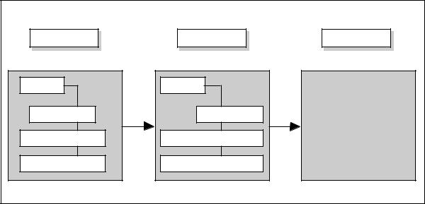
The Work Breakdown Structure (WBS) is a means of organizing system development activities based on system and product decompositions. The systems engineering process described in earlier chapters produces system and product descriptions. These product architectures, together with associated services (e.g., program management, systems engineering, etc.) are organized and depicted in a hierarchical tree-like structure that is the WBS. (See Figure 9-1.)
Because the WBS is a direct derivative of the physical and systems architectures it could be considered an output of the systems engineering process. It is being presented here as a Systems Analysis and Control tool because of its essential utility for all aspects of the systems engineering process. It
is used to structure development activities, to identify data and documents, and to organize integrated teams, and for other non-technical program management purposes.
WBS Role in DoD Systems Engineering
DoD 5000.2-R requires that a program WBS be established to provide a framework for program and technical planning, cost estimating, resource allocation, performance measurement, and status reporting. The WBS is used to define the total system, to display it as a product-oriented family tree composed of hardware, software, services, data, and facilities, and to relate these elements to each other and to the end product. Program offices are to tailor a program WBS using the guidance provided in MIL-HDBK-881.
Architecture |
WBS |
WBS Elements |
|
System |
System |
|
|
Air Vehicle |
1000 Air Vehicle |
• |
|
• |
|||
|
|
||
|
|
1000 Aircraft Subsystems |
|
Aircraft Subsystems |
1000 Aircraft Subsystems |
1610 Landing Gear |
|
|
|
||
Landing Gear System |
1610 Landing Gear System |
• |
|
• |
Figure 9–1. Architecture to WBS Flow
85
Systems Engineering Fundamentals |
Chapter 9 |
The program WBS is developed initially to define the top three levels. As the program proceeds through development and is further defined, program managers should ensure that the WBS is extended to identify all high-cost and high-risk elements for management and reporting, while ensuring the contractor has complete flexibility to extend the WBS below the reporting requirement to reflect how work will be accomplished.
Basic Purposes of the WBS
Organizational:
The WBS provides a coordinated, complete, and comprehensive view of program management. It establishes a structure for organizing system development activities, including IPT design, development, and maintenance.
Business:
It provides a structure for budgets and cost estimates. It is used to organize collection and analysis of detailed costs for earned value reports (Cost Performance Reports or Cost/Schedule Control System Criteria reporting).
Technical:
The WBS establishes a structure for:
•Identifying products, processes, and data,
•Organizing risk management analysis and tracking,
•Enabling configuration and data management. It helps establish interface identification and control.
•Developing work packages for work orders and material/part ordering, and
•Organizing technical reviews and audits.
The WBS is used to group product items for specification development, to develop Statements of Work (SOW), and to identify specific contract deliverables.
WBS – Benefits
The WBS allows the total system to be described through a logical breakout of product elements into work packages. A WBS, correctly prepared, will account for all program activity. It links program objectives and activities with resources, facilitates initial budgets, and simplifies subsequent cost reporting. The WBS allows comparison of various independent metrics and other data to look for comprehensive trends.
It is a foundation for all program activities, including program and technical planning, event schedule definition, configuration management, risk management, data management, specification preparation, SOW preparation, status reporting and problem analysis, cost estimates, and budget formulation.
9.2 WBS DEVELOPMENT
The physical and system architectures are used to prepare the WBS. The architectures should be reviewed to ensure that all necessary products and services are identified, and that the top-down structure provides a continuity of flow down for all tasks. Enough levels must be provided to identify work packages for cost/schedule control purposes. If too few levels are identified, then management visibility and integration of work packages may suffer. If too many levels are identified, then program review and control actions may become excessively time-consuming.
The first three WBS Levels are organized as: Level 1 – Overall System
Level 2 – Major Element (Segment)
Level 3 – Subordinate Components (Prime Items)
Levels below the first three represent component decomposition down to the configuration item level. In general, the government is responsible for the development of the first three levels, and the contractor(s) for levels below three.
86