

Диплом ИМЭ, ССК / Диплом / diplom / Приложения / HANDBOOK_DOD-Systems-Engineering-Guide-2001-01
.pdfChapter 4 |
Requirements Analysis |
•Refine customer objectives and requirements;
•Define initial performance objectives and refine them into requirements;
•Identify and define constraints that limit solutions; and
•Define functional and performance requirements based on customer provided measures of effectiveness.
In general, Requirements Analysis should result in a clear understanding of:
•Functions: What the system has to do,
•Performance: How well the functions have to be performed,
•Interfaces: Environment in which the system will perform, and
•Other requirements and constraints.
The understandings that come from requirements analysis establish the basis for the functional and physical designs to follow. Good requirements
analysis is fundamental to successful design definition.
Inputs
Typical inputs include customer needs and objectives, missions, MOE/MOS, environments, key performance parameters (KPPs), technology base, output requirements from prior application of SEP, program decision requirements, and suitability requirements. (See Figure 4-2 for additional considerations.)
Input requirements must be comprehensive and defined for both system products and system processes such as development, manufacturing, verification, deployment, operations, support, training and disposal (eight primary functions).
Role of Integrated Teams
The operator customers have expertise in the operational employment of the product or item being developed. The developers (government and contractor) are not necessarily competent in the operational aspects of the system under development. Typically, the operator’s need is neither clearly nor completely expressed in a way directly
•Inputs converted to putputs:
–Customer requirements
–Mission and MOEs (MNS, ORD)
–Maintenance concept and other life-cycle function planning
–SE outputs from prior development efforts
•Controls:
–Laws and organizational policies and procedures
–Military specific requirements
–Utilization environments
Inputs
– Tech base and other constraints Transformed into Outputs
•Enablers:
–Multi-disciplinary product teams
–Decision and requirements database including system/configuration item descriptions from prior efforts
–System analysis and control
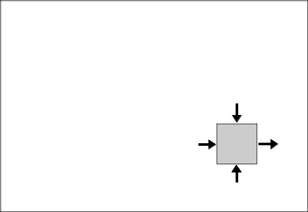
Controls
Requirements
Outputs
Analysis
Enablers
Figure 4-2. Inputs to Requirements Analysis
37
Systems Engineering Fundamentals |
Chapter 4 |
usable by developers. It is unlikely that developers will receive a well-defined problem from which they can develop the system specification. Thus, teamwork is necessary to understand the problem and to analyze the need. It is imperative that customers are part of the definition team.
On the other hand, customers often find it easier to describe a system that attempts to solve the problem rather than to describe the problem itself. Although these “solutions” may be workable to some extent, the optimum solution is obtained through a proper technical development effort that properly balances the various customer mission objectives, functions, MOE/MOS, and constraints. An integrated approach to product and process development will balance the analysis of requirements by providing understanding and accommodation among the eight primary functions.
Requirements Analysis Questions
Requirements Analysis is a process of inquiry and resolution. The following are typical questions that can initiate the thought process:
•What are the reasons behind the system development?
•What are the customer expectations?
•Who are the users and how do they intend to use the product?
•What do the users expect of the product?
•What is their level of expertise?
•With what environmental characteristics must the system comply?
•What are existing and planned interfaces?
•What functions will the system perform, expressed in customer language?
•What are the constraints (hardware, software, economic, procedural) to which the system must comply?
•What will be the final form of the product: such as model, prototype, or mass production?
This list can start the critical, inquisitive outlook necessary to analyze requirements, but it is only the beginning. A tailored process similar to the one at the end of this chapter must be developed to produce the necessary requirements analysis outputs.
4.3REQUIREMENTS ANALYSIS OUTPUTS
The requirements that result from requirements analysis are typically expressed from one of three perspectives or views. These have been described as the Operational, Functional, and Physical views. All three are necessary and must be coordinated to fully understand the customers’ needs and objectives. All three are documented in the decision database.
Operational View
The Operational View addresses how the system will serve its users. It is useful when establishing requirements of “how well” and “under what condition.” Operational view information should be documented in an operational concept document that identifies:
•Operational need definition,
•System mission analysis,
•Operational sequences,
•Operational environments,
•Conditions/events to which a system must respond,
•Operational constraints on system,
•Mission performance requirements,
•User and maintainer roles (defined by job tasks and skill requirements or constraints),
38
Chapter 4 |
Requirements Analysis |
•Structure of the organizations that will operate, support and maintain the system, and
•Operational interfaces with other systems.
Analyzing requirements requires understanding the operational and other life cycle needs and constraints.
Functional View
The Functional View focuses on WHAT the system must do to produce the required operational behavior. It includes required inputs, outputs, states, and transformation rules. The functional requirements, in combination with the physical requirements shown below, are the primary sources of the requirements that will eventually be reflected in the system specification. Functional View information includes:
•System functions,
•System performance,
–Qualitative — how well
–Quantitative — how much, capacity
–Timeliness — how often
•Tasks or actions to be performed,
•Inter-function relationships,
•Hardware and software functional relationships,
•Performance constraints,
•Interface requirements including identification of potential open-system opportunities (potential standards that could promote open systems should be identified),
•Unique hardware or software, and
•Verification requirements (to include inspection, analysis/simulation, demo, and test).
Physical View
The Physical View focuses on HOW the system is constructed. It is key to establishing the physical interfaces among operators and equipment, and technology requirements. Physical View information would normally include:
•Configuration of System:
–Interface descriptions,
–Characteristics of information displays and operator controls,
–Relationships of operators to system/ physical equipment, and
–Operator skills and levels required to perform assigned functions.
•Characterization of Users:
–Handicaps (special operating environments), and
–Constraints (movement or visual limitations).
•System Physical Limitations:
–Physical limitations (capacity, power, size, weight),
–Technology limitations (range, precision, data rates, frequency, language),
–Government Furinished Equipment (GFE), Commercial-Off-the-Shelf (COTS), Nondevelopmental Item (NDI), reusability requirements, and
–Necessary or directed standards.
4.4 SUMMARY POINTS
•An initial statement of a need is seldom defined clearly.
•A significant amount of collaboration between various life cycle customers is necessary to produce an acceptable requirements document.
•Requirements are a statement of the problem to be solved. Unconstrained and nonintegrated requirements are seldom sufficient for designing a solution.
39
Systems Engineering Fundamentals |
Chapter 4 |
•Because requirements from different customers will conflict, constraints will limit options, and resources are not unlimited; trade studies
must be accomplished in order to select a balanced set of requirements that provide feasible solutions to customer needs.
40

Chapter 4 |
Requirements Analysis |
SUPPLEMENT 4-A
A PROCEDURE FOR
REQUIREMENTS ANALYSIS
The following section provides a list of tasks that represents a plan to analyze requirements. Part of this notional process is based on the 15 requirements analysis tasks listed in IEEE P1220. This industry standard and others should be consulted when preparing engineering activities to help identify and structure appropriate activities.
As with all techniques, the student should be careful to tailor; that is, add or subtract, as suits the particular system being developed. Additionally, these tasks, though they build on each other, should not be considered purely sequential. Every task contributes understanding that may cause a need to revisit previous task decisions. This is the nature of all System Engineering activities.
Preparation: Establish and
Maintain Decision Database
When beginning a systems engineering process, be sure that a system is in place to record and manage the decision database. The decision database is an historical database of technical decisions and
requirements for future reference. It is the primary means for maintaining requirements traceability. This database decision management system must be developed or the existing system must be reviewed and upgraded as necessary to accommodate the new stage of product development. A key part of this database management system is a Requirements Traceability Matrix that maps requirements to subsystems, configuration items, and functional areas.
This must be developed, updated, and reissued on a regular basis. All requirements must be recorded.
Remember: If it is not recorded, it cannot be an approved requirement!
The 15 Tasks of IEEE P1220
The IEEE Systems Engineering Standard offers a process for performing Requirements Analysis that comprehensively identifies the important tasks that must be performed. These 15 task areas to be analyzed follow and are shown in Figure 4-3.
1. |
Customer expectations |
9. |
LIfe cycle |
2. |
Project and enterprise constraints |
10. |
Functional requirements |
3. |
External constraints |
11. |
Performance requirements |
4. |
Operational scenarios |
12. |
Modes of operation |
5. |
Measure of effectiveness (MOEs) |
13. |
Technical performance measures |
6. |
System boundaries |
14. |
Physical characteristics |
7. |
Interfaces |
15. |
Human systems integration |
8. |
Utilization environments |
|
|
Figure 4-3. IEEE P1220 Requirements Analysis Task Areas
41
Systems Engineering Fundamentals |
Chapter 4 |
Task 1. Customer Expectations
Define and quantify customer expectations. They may come from any of the eight primary functions, operational requirements documents, mission needs, technology-based opportunity, direct communications with customer, or requirements from a higher system level. The purpose of this task is to determine what the customer wants the system to accomplish, and how well each function must be accomplished. This should include natural and induced environments in which the product(s) of the system must operate or be used, and constraints (e.g. funding, cost, or price objectives, schedule, technology, nondevelopmental and reusable items, physical characteristics, hours of operation per day, on-off sequences, etc.).
Task 2. Project and Enterprise Constraints
Identify and define constraints impacting design solutions. Project specific constraints can include:
•Approved specifications and baselines developed from prior applications of the Systems Engineering Process,
•Costs,
•Updated technical and project plans,
•Team assignments and structure,
•Control mechanisms, and
•Required metrics for measuring progress.
Enterprise constraints can include:
•Management decisions from a preceding technical review,
•Enterprise general specifications,
•Standards or guidelines,
•Policies and procedures,
•Domain technologies, and
•Physical, financial, and human resource allocations to the project.
Task 3. External Constraints
Identify and define external constraints impacting design solutions or implementation of the Systems Engineering Process activities. External constraints can include:
•Public and international laws and regulations,
•Technology base,
•Compliance requirements: industry, international, and other general specifications, standards, and guidelines which require compliance for legal, interoperability, or other reasons,
•Threat system capabilities, and
•Capabilities of interfacing systems.
Task 4. Operational Scenarios
Identify and define operational scenarios that scope the anticipated uses of system product(s). For each operational scenario, define expected:
•Interactions with the environment and other systems, and
•Physical interconnectivities with interfacing systems, platforms, or products.
Task 5. Measures of Effectiveness and
Suitability (MOE/MOS)
Identify and define systems effectiveness measures that reflect overall customer expectations and satisfaction. MOEs are related to how well the system must perform the customer’s mission. Key MOEs include mission performance, safety, operability, reliability, etc. MOSs are related to how well the system performs in its intended environment and includes measures of supportability, maintainability, ease of use, etc.
42
Chapter 4 |
Requirements Analysis |
Task 6. System Boundaries
Define system boundaries including:
•Which system elements are under design control of the performing activity and which fall outside of their control, and
•The expected interactions among system elements under design control and external and/or higher-level and interacting systems outside the system boundary (including open systems approaches).
Task 7. Interfaces
Define the functional and physical interfaces to external or higher-level and interacting systems, platforms, and/or products in quantitative terms (include open systems approach). Functional and physical interfaces would include mechanical, electrical, thermal, data, control, procedural, and other interactions. Interfaces may also be considered from an internal/external perspective. Internal interfaces are those that address elements inside the boundaries established for the system addressed. These interfaces are generally identified and controlled by the contractor responsible for developing the system. External interfaces, on the other hand, are those which involve entity relationships outside the established boundaries, and these are typically defined and controlled by the government.
Task 8. Utilization Environments
Define the environments for each operational scenario. All environmental factors (natural or induced) which may impact system performance must be identified and defined. Environmental factors include:
•Weather conditions (e.g., rain, snow, sun, wind, ice, dust, fog),
•Temperature ranges,
•Topologies (e.g., ocean, mountains, deserts, plains, vegetation),
•Biological (e.g., animal, insects, birds, fungi),
•Time (e.g., dawn, day, night, dusk), and
•Induced (e.g., vibration, electromagnetic, chemical).
Task 9. Life Cycle Process Concepts
Analyze the outputs of tasks 1-8 to define key life cycle process requirements necessary to develop, produce, test, distribute, operate, support, train, and dispose of system products under development. Use integrated teams representing the eight primary functions. Focus should be on the cost drivers and higher risk elements that are anticipated to impact supportability and affordability over the useful life of the system.
Task 10. Functional Requirements
Define what the system must accomplish or must be able to do. Functions identified through requirements analysis will be further decomposed during functional analysis and allocation.
Task 11. Performance Requirements
Define the performance requirements for each higher-level function performed by the system. Primary focus should be placed on performance requirements that address the MOEs, and other KPPs established in test plans or identified as interest items by oversight authorities.
Task 12. Modes of Operation
Define the various modes of operation for the system products under development. Conditions (e.g., environmental, configuration, operational, etc.) that determine the modes of operation should be included in this definition.
Task 13. Technical Performance Measures
(TPMs)
Identify the key indicators of system performance that will be tracked during the design process. Selection of TPMs should be limited to critical
43
Systems Engineering Fundamentals |
Chapter 4 |
technical thresholds and goals that, if not met, put the project at cost, schedule, or performance risk. TPMs involve tracking the actual versus planned progress of KPPs such that the manager can make judgments about technical progress on a by-ex- ception basis. To some extent TPM selection is phase dependent. They must be reconsidered at each systems engineering process step and at the beginning of each phase.
Task 14. Physical Characteristics
Identify and define required physical characteristics (e.g., color, texture, size, weight, buoyancy) for the system products under development. Identify which physical characteristics are true constraints and which can be changed, based on trade studies.
Task 15. Human Factors
Identify and define human factor considerations (e.g., physical space limits, climatic limits, eye movement, reach, ergonomics) which will affect operation of the system products under development. Identify which human systems integration are constraints and which can be changed based on trade studies.
Follow-on Tasks
The follow-on tasks are related to the iterative nature of the Systems Engineering Process:
Integrate Requirements:
Take an integrated team approach to requirements determination so that conflicts among and between requirements are resolved in ways that result in design requirements that are balanced in terms of both risk and affordability.
Validate Requirements:
During Functional Analysis and Allocation, validate that the derived functional and performance can be traced to the operational requirements.
Verify Requirements:
•Coordinate design, manufacturing, deployment and test processes,
•Ensure that requirements are achievable and testable,
•Verify that the design-to-cost goals are achievable, and
•Verify that the functional and physical architectures defined during Functional Analysis/ Allocation and Synthesis meet the integrated technical, cost, and schedule requirements within acceptable levels of risk.
44
Chapter 5 |
Functional Analysis and Allocation |
CHAPTER 5
FUNCTIONAL ANALYSIS
AND ALLOCATION
5.1 INTRODUCTION
The purpose of this systems engineering process activity is to transform the functional, performance, interface and other requirements that were identified through requirements analysis into a coherent description of system functions that can be used to guide the Design Synthesis activity that follows. The designer will need to know what the system must do, how well, and what constraints will limit design flexibility.
This is accomplished by arranging functions in logical sequences, decomposing higher-level functions into lower-level functions, and allocating performance from higherto lower-level functions. The tools used include functional flow block diagrams and timeline analysis; and the product is a functional architecture, i.e., a description of the system—but in terms of functions and performance parameters, rather than a physical description. Functional Analysis and Allocation facilitates traceability from requirements to the solution descriptions that are the outcome of Design Synthesis.
Functions are discrete actions (use action verbs) necessary to achieve the system’s objectives. These functions may be stated explicitly, or they may be derived from stated requirements. The functions will ultimately be performed or accomplished through use of equipment, personnel, facilities, software, or a combination.
5.2FUNCTIONAL ANALYSIS AND ALLOCATION
Functional and performance requirements at any level in the system are developed from higher-level
requirements. Functional Analysis and Allocation is repeated to define successively lower-level functional and performance requirements, thus defining architectures at ever-increasing levels of detail. System requirements are allocated and defined in sufficient detail to provide design and verification criteria to support the integrated system design.
This top-down process of translating systemlevel requirements into detailed functional and performance design criteria includes:
•Defining the system in functional terms, then decomposing the top-level functions into subfunctions. That is, identifying at successively lower levels what actions the system has to do,
•Translating higher-level performance requirements into detailed functional and performance design criteria or constraints. That is, identifying how well the functions have to be performed,
•Identifying and defining all internal and external functional interfaces,
•Identifying functional groupings to minimize and control interfaces (functional partitioning),
•Determining the functional characteristics of existing or directed components in the system and incorporating them in the analysis and allocation,
•Examining all life cycle functions, including the eight primary functions, as appropriate for the specific project,
•Performing trade studies to determine alternativefunctional approaches to meet requirements, and
45
Systems Engineering Fundamentals |
Chapter 5 |
•Revisiting the requirements analysis step as necessary to resolve functional issues.
The objective is to identify the functional, performance, and interface design requirements; it is not to design a solution…yet!
Functional Partitioning
Functional partitioning is the process of grouping functions that logically fit with the components likely to be used, and to minimize functional interfaces. Partitioning is performed as part of functional decomposition. It identifies logical groupings of functions that facilitate the use of modular components and open-system designs. Functional partitioning is also useful in understanding how existing equipment or components (including commercial) will function with or within the system.
Requirements Loop
During the performance of the Functional Analysis and Allocation process, it is expected that revisiting the requirements analysis process will be necessary. This is caused by the emergence of functional issues that will require re-examination of the higher-level requirements. Such issues might include directed components or standards that cause functional conflict, identification of a revised approach to functional sequencing, or, most likely, a conflict caused by mutually incompatible requirements.
Figure 5-1 gives an overview of the basic parameters of Functional Analysis and Allocation. The output of the process is the functional architecture. In its most basic form, the functional architecture is a simple hierarchical decomposition of the functions with associated performance requirements. As the architecture definition is refined and made more specific with the performance of the
•Outputs:
–Functional architecture and supporting detail
•Inputs:
–Outputs of the Requirements Analysis
•Enablers:
–Multi-discipline product teams, decision database; Tools & Models, such as QFD, Functional Flow Block Diagrams, IDEF, N2 charts, Requirement Allocation Sheet, Timelines, Data Flow Diagrams, State/Mode Diagrams, Behavior Diagrams
•Controls:
–Constraints; GFE, COTS, & Reusable S/W; System concept & subsystem choices; organizational procedures
•Activities:
–Define system states and modes
– Define system functions & external interfaces |
Inputs |
|
–Define functional interfaces
–Allocate performance requirements to functions
–Analyze performance
–Analyze timing and resources
–Analyze failure mode effects and criticality
–Define fault detection and recovery behavior
–Integrate functions
Controls
Functional
Analysis & Outputs
Allocation
Enablers
Figure 5-1. Functional Analysis and Allocation
46