

Novation nova laptop manual
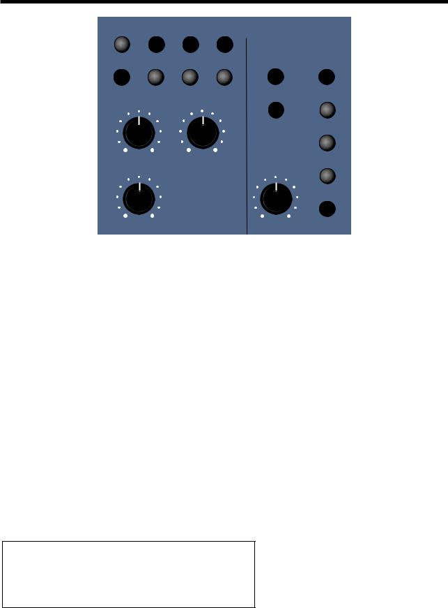
.pdfOSCILLATOR SECTION
Pitch |
- |
Button |
Level |
- |
Knob |
This combination controls the Pitch Tracking of the selected oscillator. Turning the Level Knob fully clockwise makes the selected Oscillator track the keyboard in the normal way. i.e. Notes played one octave a Part on the Master Keyboard on the keyboard are transposed one octave apart. In the “Mid” position notes played one octave a Part on the Master Keyboard are transposed 1/2 an octave a Part & fully anticlockwise notes played one octave a Part on the Master Keyboard produces no transposition at all. This can be useful for Ring Mod effects. The range of this parameter is 000 to 127.
NOTE:
This does not apply to the Noise, 1*3 & 2*3 Ring Modulator outputs. No audible effect to these sound sources will be heard if an attempt is made to adjust this parameter when these sound sources are selected.
Pitch |
- |
Button |
Mod Depth |
- |
Knob |
LFO 1 |
- |
Button |
This combination controls the Pitch Modulation of the selected Oscillator by LFO 1. Turning the Mod Depth Knob fully clockwise introduces Vibrato from LFO 1 to the selected Oscillator in a Positive direction. Turning the Mod Depth Knob fully anticlockwise introduces Vibrato from LFO 1 to the selected Oscillator in a Negative direction. In the “Mid” position there is no modulation at all. The range of this parameter is -64 to +63.
NOTE:
This does not apply to the Noise, 1*3 & 2*3 Ring Modulator outputs. No audible effect to these sound sources will be heard if an attempt is made to adjust this parameter when these sound sources are selected & the display will show “Not Available”.
Pitch |
- |
Button |
Mod Depth |
- |
Knob |
LFO 2 |
- |
Button |
This combination controls the Pitch Modulation of the selected Oscillator by LFO 2. Turning the Mod Depth Knob fully clockwise introduces Vibrato from LFO 2 to the selected Oscillator in a Positive direction. Turning the Mod Depth Knob fully anticlockwise introduces Vibrato from LFO 2 to the selected Oscillator in a Negative direction. In the “Mid” position there is no modulation at all. The range of this parameter is -64 to +63.
NOTE:
This does not apply to the Noise, 1*3 & 2*3 Ring Modulator outputs. No audible effect to these sound sources will be heard if an attempt is made to adjust this parameter when these sound sources are selected & the display will show “Not Available”.
Pitch |
- |
Button |
Mod Depth |
- |
Knob |
ENV 2 |
- |
Button |
This combination controls the Pitch Modulation of the selected Oscillator by ENV 2. Turning the Mod Depth Knob fully clockwise introduces Pitch shift from ENV 2 to the selected Oscillator in a Positive direction ( Up ). Turning the Mod Depth Knob fully anticlockwise introduces Pitch shift from ENV 2 to the selected Oscillator in a Negative direction ( Down ). In the “Mid” position there is no modulation at all. The range of this parameter is -64 to +63.
NOTE:
This does not apply to the Noise, 1*3 & 2*3 Ring Modulator outputs. No audible effect to these sound sources will be heard if an attempt is made to adjust this parameter when these sound sources are selected & the display will show “Not Available”.
59
OSCILLATOR SECTION
Pitch |
- |
Button |
Mod Depth |
- |
Knob |
ENV 3 |
- |
Button |
This combination controls the Pitch Modulation of the selected Oscillator by ENV 3. Turning the Mod Depth Knob fully clockwise introduces Pitch shift from ENV 3 to the selected Oscillator in a Positive direction ( Up ). Turning the Mod Depth Knob fully anticlockwise introduces Pitch shift from ENV 3 to the selected Oscillator in a Negative direction ( Down ). In the “Mid” position there is no modulation at all. The range of this parameter is -64 to +63.
NOTE:
This does not apply to the Noise, 1*3 & 2*3 Ring Modulator outputs. No audible effect to these sound sources will be heard if an attempt is made to adjust this parameter when these sound sources are selected & the display will show “Not Available”.
Pitch |
- |
Button |
Mod Depth |
- |
Knob |
Wheel |
- |
Button |
This combination controls the Pitch Modulation of the selected Oscillator by the Mod Wheel. Turning the Mod Depth Knob fully clockwise introduces Pitch shift from Mod Wheel to the selected Oscillator in a Positive direction ( Up ). Turning the Mod Depth Knob fully anticlockwise introduces Pitch shift from Mod Wheel to the selected Oscillator in a Negative direction ( Down ). In the “Mid” position there is no modulation at all. The range of this parameter is -64 to +63.
NOTE:
This parameter is calibrated in semitones, so a setting of 12 will produce an octave shift ( Up ) in the selected oscillator when a Mod Wheel value of 127 is received.
NOTE:
This does not apply to the Noise, 1*3 & 2*3 Ring Modulator outputs. No audible effect to these sound sources will be heard if an attempt is made to adjust this parameter when these sound sources are selected & the display will show “Not Available”.
Width |
- |
Button |
Level |
- |
Knob |
This combination controls the Pulse Width of the selected Oscillator. Turning the Level Knob fully clockwise makes the selected Oscillator Pulse Width very thin. In the mid position the Pulse Width is 25% - 75% & fully anticlockwise the Pulse Width is 50% - 50%. The range of this parameter is -64 to +63.
NOTE:
This parameter only works for Square waves & the DoubleSaw waveform. This does not apply to the Oscillators that have Saw Waveforms selected or the Noise, 1*3 & 2*3 Ring Modulator outputs. No audible effect to these sound sources will be heard if an attempt is made to adjust this parameter when these sound sources are selected & the display will show “Not Available”.
Width |
- |
Button |
Mod Depth |
- |
Knob |
LFO 1 |
- |
Button |
This combination controls the Pulse Width Modulation of the selected Oscillator by LFO 1. Turning the Mod Depth Knob fully clockwise introduces Pulse Width Modulation from LFO 1 to the selected Oscillator in a Positive direction. Turning the Mod Depth Knob fully anticlockwise introduces Pulse Width Modulation from LFO 1 to the selected Oscillator in a Negative direction. In the “Mid” position there is no modulation at all. The range of this parameter is -64 to +63.
NOTE:
This parameter only works for Square waves & the DoubleSaw waveform. This does not apply to the Oscillators that have Saw Waveforms selected or the Noise, 1*3 & 2*3 Ring Modulator outputs. No audible effect to these sound sources will be heard if an attempt is made to adjust this parameter when these sound sources are selected & the display will show “Not Available”.
60

OSCILLATOR SECTION
Width |
- |
Button |
Mod Depth |
- |
Knob |
LFO 2 |
- |
Button |
This combination controls the Pulse Width Modulation of the selected Oscillator by LFO 2. Turning the Mod Depth Knob fully clockwise introduces Pulse Width Modulation from LFO 2 to the selected Oscillator in a Positive direction. Turning the Mod Depth Knob fully anticlockwise introduces Pulse Width Modulation from LFO 2 to the selected Oscillator in a Negative direction. In the “Mid” position there is no modulation at all. The range of this parameter is -64 to +63.
NOTE:
This parameter only works for Square waves & the DoubleSaw waveform. This does not apply to the Oscillators that have Saw Waveforms selected or the Noise, 1*3 & 2*3 Ring Modulator outputs. No audible effect to these sound sources will be heard if an attempt is made to adjust this parameter when these sound sources are selected & the display will show “Not Available”.
Width |
- |
Button |
Mod Depth |
- |
Knob |
ENV 2 |
- |
Button |
This combination controls the Pulse Width Modulation of the selected Oscillator by ENV 2. Turning the Mod Depth Knob fully clockwise introduces Pulse Width Modulation from ENV 2 to the selected Oscillator in a Positive direction. Turning the Mod Depth Knob fully anticlockwise introduces Pulse Width Modulation from ENV 2 to the selected Oscillator in a Negative direction. In the “Mid” position there is no modulation at all. The range of this parameter is -64 to +63.
NOTE:
This parameter only works for Square waves & the DoubleSaw waveform. This does not apply to the Oscillators that have Saw Waveforms selected or the Noise, 1*3 & 2*3 Ring Modulator outputs. No audible effect to these sound sources will be heard if an attempt is made to adjust this parameter when these sound sources are selected & the display will show “Not Available”.
Width |
- |
Button |
Mod Depth |
- |
Knob |
ENV 3 |
- |
Button |
This combination controls the Pulse Width Modulation of the selected Oscillator by ENV 3. Turning the Mod Depth Knob fully clockwise introduces Pulse Width Modulation from ENV 3 to the selected Oscillator in a Positive direction. Turning the Mod Depth Knob fully anticlockwise introduces Pulse Width Modulation from ENV 3 to the selected Oscillator in a Negative direction. In the “Mid” position there is no modulation at all. The range of this parameter is -64 to +63.
NOTE:
This parameter only works for Square waves & the DoubleSaw waveform. This does not apply to the Oscillators that have Saw Waveforms selected or the Noise, 1*3 & 2*3 Ring Modulator outputs. No audible effect to these sound sources will be heard if an attempt is made to adjust this parameter when these sound sources are selected & the display will show “Not Available”.
Width |
- |
Button |
Mod Depth |
- |
Knob |
Wheel |
- |
Button |
This combination controls the Pulse Width Modulation of the selected Oscillator by the Mod Wheel. Turning the Mod Depth Knob fully clockwise introduces Pulse Width Modulation from the Mod Wheel to the selected Oscillator in a Positive direction. Turning the Mod Depth Knob fully anticlockwise introduces Pulse Width Modulation from the Mod Wheel to the selected Oscillator in a Negative direction. In the “Mid” position there is no modulation at all. The range of this parameter is -64 to +63.
NOTE:
This parameter only works for Square waves & the DoubleSaw waveform. This does not apply to the Oscillators that have Saw Waveforms selected or the Noise, 1*3 & 2*3 Ring Modulator outputs. No audible effect to these sound sources will be heard if an attempt is made to adjust this parameter when these sound sources are selected & the display will show “Not Available”.
61
OSCILLATOR SECTION
Sync |
- |
Button |
Level |
- |
Knob |
This combination controls the Sync Effect on the selected Oscillator. Turning the Level Knob fully clockwise introduces the maximum Sync Effect fully to the selected Oscillator & fully anticlockwise there is no Sync Effect at all. The range of this parameter is 000 to 127.
NOTE:
This does not apply to the Noise, 1*3 & 2*3 Ring Modulator outputs. No audible effect to these sound sources will be heard if an attempt is made to adjust this parameter when these sound sources are selected & the display will show “Not Available”.
Sync |
- |
Button |
Mod Depth |
- |
Knob |
LFO 1 |
- |
Button |
This combination controls the modulation of the Sync Effect on the selected Oscillator by LFO 1. Turning the Mod Depth Knob fully clockwise introduces Sync Effect from LFO 1 to the selected Oscillator in a Positive direction. Turning the Mod Depth Knob fully anticlockwise introduces Sync Effect from LFO 1 to the selected Oscillator in a Negative direction. In the “Mid” position there is no modulation at all. The range of this parameter is -64 to +63.
NOTE:
This does not apply to the Noise, 1*3 & 2*3 Ring Modulator outputs. No audible effect to these sound sources will be heard if an attempt is made to adjust this parameter when these sound sources are selected & the display will show “Not Available”.
Sync |
- |
Button |
Mod Depth |
- |
Knob |
LFO 2 |
- |
Button |
This combination controls the modulation of the Sync Effect on the selected Oscillator by LFO 2. Turning the Mod Depth Knob fully clockwise introduces Sync Effect from LFO 2 to the selected Oscillator in a Positive direction. Turning the Mod Depth Knob fully anticlockwise introduces Sync Effect from LFO 2 to the selected Oscillator in a Negative direction. In the “Mid” position there is no modulation at all. The range of this parameter is -64 to +63.
NOTE:
This does not apply to the Oscillators that have the Noise, 1*3 & 2*3 Ring Modulator outputs. No audible effect to these sound sources will be heard if an attempt is made to adjust this parameter when these sound sources are selected & the display will show “Not Available”.
Sync |
- |
Button |
Mod Depth |
- |
Knob |
ENV 2 |
- |
Button |
This combination controls the modulation of the Sync Effect on the selected Oscillator by ENV 2. Turning the Mod Depth Knob fully clockwise introduces Sync Effect from ENV 2 to the selected Oscillator in a Positive direction. Turning the Mod Depth Knob fully anticlockwise introduces Sync Effect from ENV 2 to the selected Oscillator in a Negative direction. In the “Mid” position there is no modulation at all. The range of this parameter is -64 to +63.
NOTE:
This does not apply to the Noise, 1*3 & 2*3 Ring Modulator outputs. No audible effect to these sound sources will be heard if an attempt is made to adjust this parameter when these sound sources are selected & the display will show “Not Available”.
Sync |
- |
Button |
Mod Depth |
- |
Knob |
ENV 3 |
- |
Button |
This combination controls the modulation of the Sync Effect on the selected Oscillator by ENV 3. Turning the Mod Depth Knob fully clockwise introduces Sync Effect from ENV 3 to the selected Oscillator in a Positive direction. Turning the Mod Depth Knob fully anticlockwise introduces Sync Effect from ENV 3 to the selected Oscillator in a Negative direction. In the “Mid” position there is no modulation at all. The range of this parameter is -64 to +63.
62

OSCILLATOR SECTION
NOTE:
This does not apply to the Noise, 1*3 & 2*3 Ring Modulator outputs. No audible effect to these sound sources will be heard if an attempt is made to adjust this parameter when these sound sources are selected & the display will show “Not Available”.
Sync |
- |
Button |
Mod Depth |
- |
Knob |
Wheel |
- |
Button |
This combination controls the modulation of the Sync Effect on the selected Oscillator by the Mod Wheel. Turning the Mod Depth Knob fully clockwise introduces Sync Effect from the Mod Wheel to the selected Oscillator in a Positive direction. Turning the Mod Depth Knob fully anticlockwise introduces Sync Effect from the Mod Wheel to the selected Oscillator in a Negative direction. In the “Mid” position there is no modulation at all. The range of this parameter is -64 to +63.
NOTE:
This does not apply to the Noise, 1*3 & 2*3 Ring Modulator outputs. No audible effect to these sound sources will be heard if an attempt is made to adjust this parameter when these sound sources are selected & the display will show “Not Available”.
Soften |
- |
Button |
Level |
- |
Knob |
This combination controls the Soften Effect on the selected Oscillator & noise waveforms. Turning the Level Knob fully clockwise introduces the Soften effect fully to the selected Oscillator & fully anticlockwise there is no Softening at all. The range of this parameter is 000 to 127.
NOTE:
This does not apply to the 1*3 & 2*3 Ring Modulator outputs. No audible effect to these sound sources will be heard if an attempt is made to adjust this parameter when these sound sources are selected & the display will show “Not Available”.
Soften |
- |
Button |
Mod Depth |
- |
Knob |
LFO 1 |
- |
Button |
This combination controls the modulation of the Soften effect of the selected Oscillator by LFO 1. Turning the Mod Depth Knob fully clockwise introduces Soften from LFO 1 to the selected Oscillator in a Positive direction. Turning the Mod Depth Knob fully anticlockwise introduces Soften from LFO 1 to the selected Oscillator in a Negative direction. In the “Mid” position there is no modulation at all. The range of this parameter is -64 to +63.
NOTE:
This does not apply to the Oscillators that have the, 1*3 & 2*3 Ring Modulator outputs. No audible effect to these sound sources will be heard if an attempt is made to adjust this parameter when these sound sources are selected & the display will show “Not Available”.
Soften |
- |
Button |
Mod Depth |
- |
Knob |
LFO 2 |
- |
Button |
This combination controls the modulation of the Soften Effect on the selected Oscillator by LFO 2. Turning the Mod Depth Knob fully clockwise introduces Soften Effect from LFO 2 to the selected Oscillator in a Positive direction. Turning the Mod Depth Knob fully anticlockwise introduces Soften Effect from LFO 2 to the selected Oscillator in a Negative direction. In the “Mid” position there is no modulation at all. The range of this parameter is -64 to +63.
NOTE:
This does not apply to the 1*3 & 2*3 Ring Modulator outputs. No audible effect to these sound sources will be heard if an attempt is made to adjust this parameter when these sound sources are selected & the display will show “Not Available”.
63
OSCILLATOR SECTION
Soften |
- |
Button |
Mod Depth |
- |
Knob |
ENV 2 |
- |
Button |
This combination controls the modulation of the Soften Effect on the selected Oscillator by ENV 2. Turning the Mod Depth Knob fully clockwise introduces Soften Effect from ENV 2 to the selected Oscillator in a Positive direction. Turning the Mod Depth Knob fully anticlockwise introduces Soften Effect from ENV 2 to the selected Oscillator in a Negative direction. In the “Mid” position there is no modulation at all. The range of this parameter is -64 to +63.
NOTE:
This does not apply to the 1*3 & 2*3 Ring Modulator outputs. No audible effect to these sound sources will be heard if an attempt is made to adjust this parameter when these sound sources are selected & the display will show “Not Available”.
Soften |
- |
Button |
Mod Depth |
- |
Knob |
ENV 3 |
- |
Button |
This combination controls the modulation of the Soften Effect on the selected Oscillator by ENV 3. Turning the Mod Depth Knob fully clockwise introduces Soften Effect from ENV 3 to the selected Oscillator in a Positive direction. Turning the Mod Depth Knob fully anticlockwise introduces Soften Effect from ENV 3 to the selected Oscillator in a Negative direction. In the “Mid” position there is no modulation at all. The range of this parameter is -64 to +63.
NOTE:
This does not apply to the 1*3 & 2*3 Ring Modulator outputs. No audible effect to these sound sources will be heard if an attempt is made to adjust this parameter when these sound sources are selected & the display will show “Not Available”.
Soften |
- |
Button |
Mod Depth |
- |
Knob |
Wheel |
- |
Button |
This combination controls the modulation of the Soften Effect on on the selected Oscillator by the Mod Wheel. Turning the Mod Depth Knob fully clockwise introduces Soften Effect from the Mod Wheel to the selected Oscillator in a Positive direction. Turning the Mod Depth Knob fully anticlockwise introduces Soften Effect from the Mod Wheel to the selected Oscillator in a Negative direction. In the “Mid” position there is no modulation at all. The range of this parameter is -64 to +63.
NOTE:
This does not apply to the 1*3 & 2*3 Ring Modulator outputs. No audible effect to these sound sources will be heard if an attempt is made to adjust this parameter when these sound sources are selected & the display will show “Not Available”.
64
OSCILLATOR SECTION
Menu - Button
When this button is pressed a series of pages is available on the display containing parameters relevant to this section.
In the Oscillator section there are 3 pages available. These are selected using the Page Up & Page Down buttons to the left of the display.
There are a maximum of 2 parameters displayed on any page. One for each line on the display. The “Fast Data” Knobs on the right of the display are used to alter these parameter’s values.
Page 1 looks like so:
MWheel |
LFO1 |
amt |
+1O |
ATouch |
LFO1 |
amt |
+1O |
As can be seen the higher parameter is “MWheel LFO1 amt”. In this case with a value of +10.
This parameter determines how the Mod Wheel on the Master Keyboard effects the amount of LFO1 modulation on the selected Oscillator. Use the higher Fast Data knob to adjust the value of this parameter. With this parameter it is possible to set the amount of modulation individually for each oscillator. The range of this parameter is -64 to +63. This parameter is memorised with a Program.
NOTE:
Mod Wheel LFO Amt does not apply to the 1*3, 2*3 or Noise buttons. If you attempt to alter this parameter when these buttons are selected the display will show “Menu Only Available For Osc 1,2 or 3” whilst the adjustment is being made then the display will revert back to the last edited parameter.
As can be seen the lower parameter is “AT LFO1 amt”. In this case with a value of +10.
This parameter determines how the Aftertouch on the Master Keyboard effects the amount of LFO1 modulation on the selected Oscillator. Use the lower Fast Data knob to adjust the value of this parameter. With this parameter it is possible to set the amount of modulation individually for each oscillator. The range of this parameter is -64 to +63. This parameter is memorised with a Program.
NOTE:
Aftertouch LFO1 Amt does not apply to the 1*3, 2*3 or Noise buttons. If you attempt to alter this parameter when these buttons are selected the display will show “Menu Only Available For Osc 1,2 or 3” whilst the adjustment is being made then the display will revert back to the last edited parameter.
Page 2 looks like so:
Formant width |
O1O |
Sync skew |
+1O |
As can be seen the higher parameter is “Formant width”. In this case with a value of 010.
This parameter determines how much Formant Width is applied to the selected Oscillator. Use the higher Fast Data knob to adjust the value of this parameter. With this parameter it is possible to set the amount of modulation individually for each oscillator. Refer to page 8 in the “About Analogue Synthesis section” for details on this parameter. The range of this parameter is 000 to 127. This parameter is memorised with a Program.
NOTE:
Formant Width does not apply to the 1*3, 2*3 or Noise buttons. If you attempt to alter this parameter when these buttons are selected the display will show “Menu Only Available For Osc 1,2 or 3” whilst the adjustment is being made then the display will revert back to the last edited parameter.
65

OSCILLATOR SECTION
As can be seen the lower parameter is “Sync skew”. In this case with a value of +10.
This parameter determines how much of the Sync Skew effect is applied to the selected Oscillator. Use the lower Fast Data knob to adjust the value of this parameter. With this parameter it is possible to set the amount of modulation individually for each oscillator. Refer to page 8 in the “About Analogue Synthesis section” for details on this parameter. The range of this parameter is -64 to +63. This parameter is memorised with a Program.
NOTE:
Sync Skew does not apply to the 1*3, 2*3 or Noise buttons. If you attempt to alter this parameter when these buttons are selected the display will show “Menu Only Available For Osc 1,2 or 3” whilst the adjustment is being made then the display will revert back to the last edited parameter.
Page 3 looks like so:
Sync key follow |
O1O |
Pitch bend range |
+1O |
As can be seen the higher parameter is “Sync key follow”. In this case with a value of 010.
This parameter determines how the “Virtual” Sync oscillator is transposed across the keyboard for the selected Oscillator. Use the higher Fast Data knob to adjust the value of this parameter. With this parameter it is possible to set the amount of modulation individually for each oscillator. Refer to page 8 in the “About Analogue Synthesis section” for details on this parameter. The range of this parameter is 000 to 127. This parameter is memorised with a Program.
NOTE:
Sync Key Follow does not apply to the 1*3, 2*3 or Noise buttons. If you attempt to alter this parameter when these buttons are selected the display will show “Menu Only Available For Osc 1,2 or 3” whilst the adjustment is being made then the display will revert back to the last edited parameter.
As can be seen the lower parameter is “Pitch bend range”. In this case with a value of +10.
This parameter determines how the Pitch Bend Wheel on the Master Keyboard effects the pitch of the oscillators. Use the lower Fast Data knob to adjust the value of this parameter. With this parameter it is possible to set the pitch bend range individually for each oscillator allowing the creation of effects like using the Pitch bend control to bend into a chord. The range is -12 to +12 in semitone steps. This parameter is memorised with a Program.
NOTE:
Pitch bend Range does not apply to the 1*3, 2*3 or Noise buttons. If you attempt to alter this parameter when these buttons are selected the display will show “Menu Only Available For Osc 1,2 or 3” whilst the adjustment is being made then the display will revert back to the last edited parameter.
66
FILTER SECTION
Filters
|
|
|
|
modulation |
|
menu |
12dB |
18dB |
24dB |
destination |
source |
special |
low |
band |
high |
frequency |
lfo 1 |
|
|
|
|
resonance |
lfo 2 |
frequency |
resonance |
|
env 2 |
||
|
|
|
|
|
env 3 |
overdrive |
|
|
mod depth |
wheel |
|
This section contains all the knobs & buttons associated with the Filter
12dB |
- |
Button |
18dB |
- |
Button |
24dB |
- |
Button |
These buttons select the slope of the cutoff curve of the Filter. Only one can be selected at once. The effect is similar to a “Q” control on a parametric EQ. In the 12db position the Cutoff Frequency slope is less steep so in a Low Pass Filter the higher frequencies are not attenuated as much as they are in the 24 or 18db positions. This makes the resulting filtering in the 12db position more subtle than the 24db or 18db positions which you should select if you want the Cutoff Frequency to be more obvious.
Low |
- |
Button |
High |
- |
Button |
Band |
- |
Button |
These buttons select the type of Filter to be used in this program. All have a very different sound. Below is a description of what parts of the sound the different Filters allow through the Filter. The Low button configures the Filter into a Low Pass Filter. A Low Pass Filter allows harmonics below a set frequency to pass through the Filter. Hence the name Low Pass Filter. The High button configures the Filter into a High Pass Filter. A High Pass Filter allows harmonics above a set frequency to pass through the Filter. Hence the name High Pass Filter. The Band button configures the Filter into a Band Pass Filter. A Band Pass Filter allows harmonics at a set frequency to pass through the Filter, the harmonics above & below the set frequency do not pass through the Filter. Hence the name Band Pass Filter. The setting of these buttons is memorised with a Program.
Special - Button
When the special filter button is pressed the display shows:
Filter |
type |
Res LPF |
Filter |
width |
OO |
The higher parameter is “Filter type”. In this case with a value of Res LPF.
This parameter determines what type of Special filter is applied. Use the Higher data knob to adjust this parameter. There are 9 different special filters. Each one is made up of 2 filter blocks. The “Hyper Resonant” types are in series & are the Res LPF, Res BPF & Res HPF filters. These types are very resonant & the Filter width parameter allows the Cutoff frequencies of each filter block to be set at different frequencies. The rest of the filter types have the 2 filter blocks in parallel. Again the Filter width parameter allows the Cutoff frequencies of each filter block to be set at different frequencies. The range of this parameter is Res LPF, Res BPF, Res
HPF, Notch, LPF + LPF, BPF + BPF, HPF + HPF, LPF + BPF, & BPF + HPF. This parameter is memorised with a program.
67
FILTER SECTION
The lower parameter is “Filter width”. In this case with a value of 00.
This parameter determines the spacing/offset in filter cutoff frequencies between the two elements of the “Special” filters. This is a duplicate of the Special type filter width parameter that is displayed on page 6 of the Filter menu. The reason for this is that it was found to be nice for the display to jump back to this parameter when editing & as this parameter is duplicated in the Filter menu it will do that when the Filter menu is selected. This can provide “Formant” type filters & speech like qualities can be easily realised. The Filter width is calibrated in semitones & a range of pre-set intervals are available. The range of this parameter is 00, 08, 16, 24, 32, 40, 48 & 56. Note that the Resonance modulation Knob in the Filter Modulation Matrix actually modulates the “Filter width” parameter & not the resonance when the “Special” filters are selected. The Resonance knob still retains its function as filter Resonance when in this mode. This parameter is memorised with a program.
NOTE:
Adjusting the value of this parameter will alter the value in the Filter menu. It is not possible to have different values set in the 2 pages.
Frequency - Knob
This knob controls the “Cutoff Frequency” of the Filter. Fully Clockwise & the Filters Cutoff frequency is set to the highest position, generally this produces a very trebly sound. Fully anticlockwise & the Filters Cutoff frequency is set to the lowest position, generally producing a very mellow sound. The range of this parameter is 000 to 127. This parameter is memorised with a Program.
NOTE:
It is possible to set the Filter so that it Filters out all of the sound. This normally happens at extreme settings. i.e. The Frequency knob set fully anticlockwise in Low Pass Filter mode or the Frequency knob set fully clockwise in the High Pass Filter mode.
Resonance - Knob
This knob controls the amount of Resonance the Filter has. The effect is to emphasise the harmonics around the Cutoff Frequency ( Set by the Frequency knob above ). For this reason on some synths this control is known as Emphasis. Fully anticlockwise there is no boosting of the Cutoff Frequency, but as you turn the knob clockwise this frequency will be boosted until fully clockwise it goes in to oscillation producing a new pitched element ( similar to feedback on an electric guitar ). Increasing the Resonance is very good for bringing out modulation ( movement or change ) in the Filters Cutoff Frequency, such as TB303 basslines. The range of this parameter is 000 to 127. This parameter is memorised with a Program.
Overdrive - Knob
This knob determines how much Overdrive is applied to the Filter. This can warm sounds up & give them a different harmonic content from the standard waveforms, “Warmer” sounds are produced by modelling the “Saturation effect” common in classic Analogue Filters. Fully anticlockwise the signal will be unaffected by the Overdrive. Fully clockwise & full drive will be applied. The range of this parameter is 000 to 127. This parameter is memorised with a Program.
68