

2 - 66 SUSPENSION/DRIVESHAFTS
REAR LEVELING DIAGNOSTIC PROCEDURES
Fig. 7 Control Module Connector
SELF-DIAGNOSTICS
A self-diagnostic procedure is available for the service technician to use to detect system malfunctions.
BEFORE DIAGNOSTICS TEST
Check the 20 amp fuse (position W40) and the 30 amp circuit breaker (position W5) to be assured they are functional components.
Check all connectors that link the system into the main body wiring harness. These include the (compressor, height sensor, control module, (Fig. 7) relay, underbody to in trunk and leveling harness to main body harness connectors). Also, check all air lines, connectors, and other components for correct installation.
TEST LAMP PIN OPERATION
The monitor lamp pin output will be activated (test lamp on) if the detection of abnormal system operation is determined by the CM.
AFTER COMPLETION OF REPAIRS
To initiate diagnostics, disconnect the test ground wire then reconnect for repair verification.
TERMINATION OF SELF-DIAGNOSTICS
The self-diagnostic operation is terminated when any of the following takes place:
²Disconnecting the diagnostic input from the ground circuit.
²Turn the ignition switch to the off position.
When the self-diagnostic operation is terminated. The control module resumes normal operation unless it ceases operation. Due to it detecting a system malfunction.
TEST WEIGHT
Weight between 275-300 lbs. must be added to rear of vehicle before diagnostic testing begins.
DIAGNOSTICS (TO START PROCESS)
(1)Remove protective connector cover from diagnostic connector.
(2)Insert wire into diagnostic ground pin. Then
Ä
attach to compressor ground pin, or as an alternate, insert wire into diagnostic ground pin. Then ground other end of test wire to body structure or a control module fastener.
IGNITION
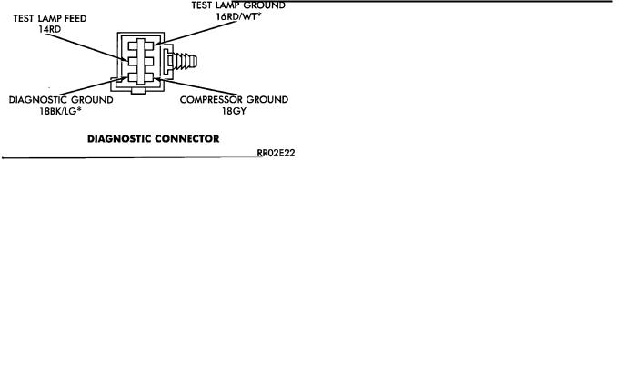
The following self-diagnostic operation is initiated only by connecting the diagnostic ground pin to ground after the ignition switch is turned ON. A monitor lamp must be connected between the Test Lamp Ground Pin and the Test Lamp Feed Pin to display the control module diagnostics status. See (Fig. 8) for diagnostic test pin locations.
Fig. 8 Diagnostic Test Pin Location
OPERATION
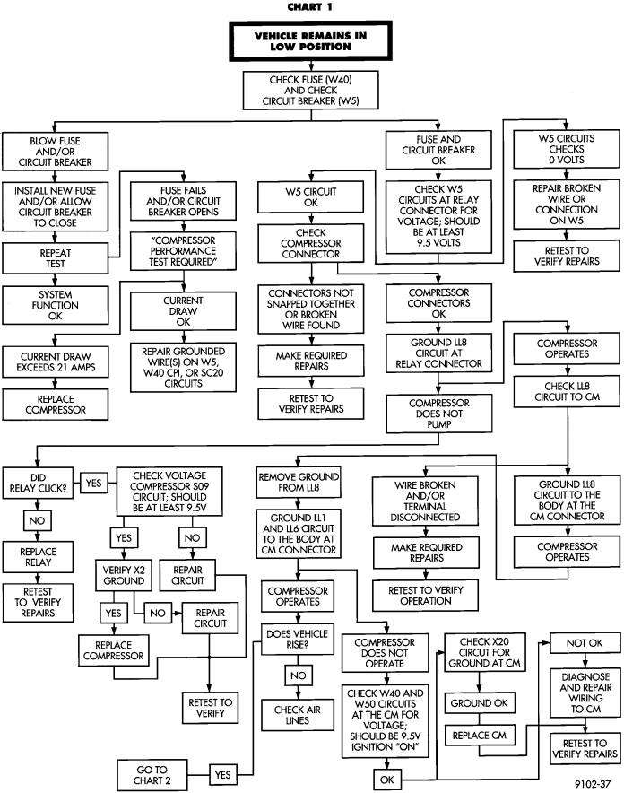
(1)The compressor relay output. From the control module (CM), is activated until the vehicle is in the high position. The maximum relay output operation time is 150 610 seconds. If the expected position is not obtained, the CM ceases self-diagnostics and any further operation. (I.e. neither operates the compressor relay or exhaust outputs). The monitor lamp output is continuously activated until the ignition is cycled from OFF to ON or 60 61 minutes has elapsed after ignition was turned off. See Diagnostics Chart 1.
(2)The monitor lamp output should flash to indicate the position of the height sensor. The sensor should be in the high position. A continuously lighted monitor lamp will indicate a system failure. Such as the compressor relay output has operated for 150 610 seconds but the height sensor did not move to the high position within the right shock absorber). See Diagnostic Chart 1.
(3)Next the exhaust solenoid output is activated until the vehicle is in the low position. The maximum exhaust solenoid operation time is 120 610 seconds. If the expected position is not obtained, the module ceases self-diagnostics and any further operation. The monitor lamp output is lighted continuously until ignition is cycled from OFF to ON or 60 61 minutes has elapsed after ignition is turned off. See Diagnostic Chart 4.
(4)The monitor lamp should flash to indicate the height sensor is in the low position. A continuously

Ä
lighted monitor lamp will indicate a system failure. Such as the exhaust solenoid operated for 120 610 seconds but the height sensor did not move to the low position. See Diagnostic Chart 4.
(5) The compressor relay output is activated to return the vehicle to the neutral (leveled) position. The maximum operation time of the relay output is 150 610 seconds. If the expected position is not obtained. The control module ceases self-diagnostics and any further operation. The monitor lamp is continuously lighted until the ignition is cycled from OFF to ON or 60 61 minutes has elapsed after ignition is turned off.
The sensor will move to the neutral position. If not, a continuously lighted monitor lamp will indicate a
SUSPENSION/DRIVESHAFTS 2 - 67
system failure. Such as the compressor relay output operated for 150 610 seconds but the sensor did not move to or sense the neutral position. See Diagnostic Chart 1.
(6) Completion of Diagnostics When the self diagnostic procedure is successfully completed, the control module resumes normal operation. The diagnostic test is now complete. Throughout the testing the vehicle load must be maintained at a specific level. No loads are allowed to be added/removed to/from the vehicle once the self diagnosis tests have been initiated.
The Diagnostic connector cover must be installed after completion of the test.
2 - 68 SUSPENSION/DRIVESHAFTS |
|
Ä |
|
AUTOMATIC AIR LOAD LEVELING DIAGNOSTICS
Ä |
|
SUSPENSION/DRIVESHAFTS 2 - 69 |
|