

8F - 2 AUDIO SYSTEM |
|
Ä |
|
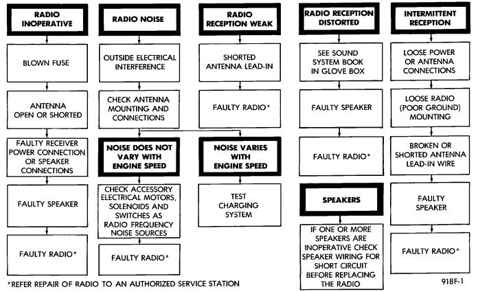
Fig. 2 Radio Diagnosis
(3)Pull radio from panel and disconnect wiring, ground strap and antenna lead from radio.
(4)Remove radio.
INSTALLATION
(1)Connect wiring, ground strap and antenna lead to radio.
(2)Position radio into panel, install mounting screws and tighten securely.
(3)Install center bezel.
AG AND AJ BODIES
REMOVAL
(1)Remove center instrument panel bezel by pulling toward the rear of the car (Fig. 5).
(2)Remove two screws attaching radio to console.
(3)Pull radio through front face of console, disconnect wiring harness, antenna lead, and ground strap.
INSTALLATION
(1)Position radio so that the wiring harness, antenna lead, and ground strap can be connected.
(2)Install two screws attaching radio to console.
(3)Install center bezel by pushing in until clips engage.
AC AND AY BODIES
REMOVAL
(1)Remove four cluster bezel screws (Fig. 6).
(2)Remove two radio attaching screws.
(3)Disconnect wiring connectors and antenna
cable.
(4)Remove screw attaching ground strap.
INSTALLATION
(1)Secure ground strap with attaching screw.
(2)Connect wiring and antenna cable.
(3)Install radio and cluster bezel.
AP BODY REPLACEMENT
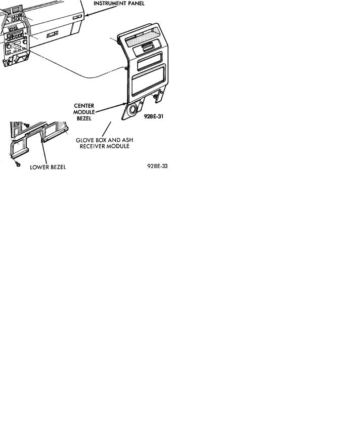
(1)Remove center module bezel (Fig. 7).
(2)Remove lower center module cover if equipped with base console.
(3)Remove right console side wall if equipped with full console assembly.
(4)Remove two mounting screws on the radio and pull out of instrument panel (Fig. 8).
(5)Disconnect wiring and antenna cable.
(6)Remove ground strap from radio.
(7)For installation reverse above procedures.
Ä |
|
AUDIO SYSTEM 8F - 3 |
|
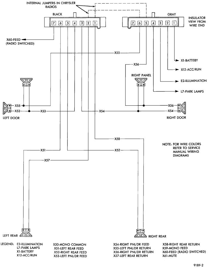
Fig. 3 Radio Connector Circuits
8F - 4 AUDIO SYSTEM |
|
Ä |
|
Fig. 4 Radio AssemblyÐAA BODY
Fig. 6 Radio AssemblyÐAC and AY Bodies
Fig. 5 Radio AssemblyÐAG and AJ Bodies
Fig. 7 Center Module Bezel
Fig. 8 Radio AssemblyÐAP Body