

Ä |
|
SPEED CONTROL SYSTEM 8H - 7 |
|
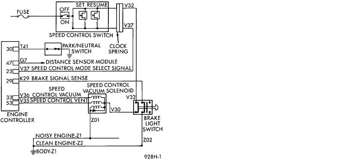
Fig. 11 Speed Control Circuit
SPEED CONTROL SYSTEM ELECTRICAL TESTS
WARNING: IF REMOVAL OF AIR BAG MODULE IS NECESSARY, REFER TO GROUP 8M, RESTRAINT SYSTEMS.
Electronic speed control systems may be tested using two different methods. One involves use of a DRB II. If this test method is desired, refer to the Powertrain Diagnostic Test Procedures for charging and speed control system manual.
The other test method uses a volt/ohm meter and is described in the following tests.
If any information is needed concerning wiring, refer to Group 8W, Wiring Diagrams.
CAUTION: When test probing for voltage or continuity at electrical connectors, care must be taken not to damage connector, terminals, or seals. If these components are damaged, intermittent or complete system failure may occur.
SERVO ELECTRICAL TESTS
WARNING: ON VEHICLES EQUIPPED WITH AIRBAG, SEE GROUP 8M, RESTRAINT SYSTEMS FOR AIRBAG, STEERING WHEEL OR COLUMN REMOVAL PROCEDURES.
(1)Turn ignition switch to the ON position. With the speed control switch in the ON position, set up a voltmeter to read battery voltage and connect the negative lead to a good chassis ground.
(2)Disconnect the four-way connector going to the servo (Fig. 12). Test pin 2 of the main harness four-
Fig. 12 Servo Harness Connector
way connector for battery voltage. If not OK go to step 3. If voltage is OK go to step 4.
(3)Perform the following tests.
(a)Disconnect the six-way connector at the stop lamp switch and test pin 1 of the main harness for battery voltage. If voltage is OK perform the stop lamp switch test.
(b)If the stop lamp switch tests OK; repair wire between the servo and the stop lamp switch.
(c)If no voltage at pin 1 at the 6-way stop lamp connector, remove the speed control switch and disconnect the four-way connector. Test pin 1 of main harness for battery voltage.
(d)If voltage is OK perform the speed control switch test.
(e)If speed control switch is OK, test continuity across the clockspring.
(f)If clockspring OK, repair as required, wire between stop lamp switch and clockspring.
(g)If no voltage at pin 1 of the 4-way speed control switch connector.
²Test for battery voltage between the ignition and the fuse
²If voltage OK, check fuse
²If fuse OK, repair wire between fuse and clockspring
(4)Connect a jumper wire between pin 2 of the four-way servo connector of the main harness and pin 2 of the speed control servo (Fig. 12). The other three pins from the servo should show battery voltage. If not, replace the servo.
(5)Using an ohmmeter, connect one lead to a good body ground and the other lead touch pin 1 in the four-way servo connector of the main harness. The meter should show continuity. If not, repair the ground circuit as necessary.
8H - 8 SPEED CONTROL SYSTEM
ENGINE CONTROLLER ELECTRICAL TEST
WARNING: ON VEHICLES EQUIPPED WITH AIRBAG, SEE GROUP 8M, RESTRAINT SYSTEMS FOR AIRBAG, STEERING WHEEL OR COLUMN REMOVAL PROCEDURES.
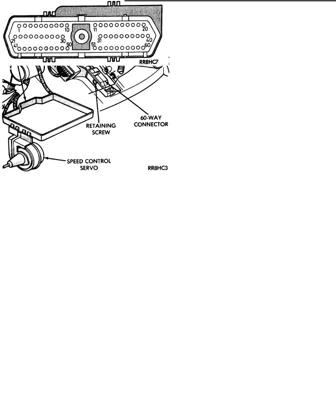
(1) Unplug 60-way connector from the engine controller, located next to the battery (Fig. 13).
Fig. 13 Engine Controller and Connector Location
(2)Remove speed control switch. Refer to Speed Control Switch Removal. Disconnect the 4-way connector.
(3)Using an ohmmeter test continuity between pin 23 of engine controller and pin 4 of the speed control switch harness. Refer to Fig. 14 for controller terminal locations.
Fig. 14 Engine Controller 60-Way Connector Shown
from Terminal End
(a)If no continuity, repair wire circuit as neces-
sary.
(b)Continuity OK, refer to Speed Control Switch
Test.
(4)Connect the 4-way connector to speed control switch.
Ä
(5)Connect negative lead of voltmeter to a good body ground near the engine controller.
(4)Turn ignition switch ON.
(5)Place speed control switch in the OFF position. Touch the positive lead of the voltmeter to pin 53, the voltmeter should read 0 volts.
(6)Place speed control switch in the ON position. Touch the positive lead of the voltmeter to pin 53, the voltmeter should read battery voltage.
(7)If no voltage, repair the wire between pin 53 and pin 3 of the speed control servo (Fig. 6). If voltage is OK go to step 8.
(8)Place speed control switch in the OFF position. Touch the positive lead of the voltmeter to pin 33, voltmeter should read 0 volts.
(9)Place speed control switch in the ON position. Touch the positive lead of the voltmeter to pin 33, the voltmeter should read battery voltage.
(10)If no voltage, repair the wire between pin 33 and pin 4 of the speed control servo (Fig. 6). If voltage is OK go to step 11.
(11)Using an ohmmeter, connect one lead to a good body ground and touch the other lead to pin 29. With the brake pedal released, the meter should show continuity. When the pedal is depressed, the meter should show no continuity. If no continuity perform the following test. Continuity OK, go to step 12.
(a)Using an ohmmeter test continuity between pin 29 of engine controller and pin 3 of the stop lamp switch connector.
(b)If no continuity, repair as necessary.
(c)If continuity, refer to Stop Lamp Switch Test.
(d)If stop lamp switch test OK, Test continuity between pin 6 of stop lamp switch and ground.
(12)Using an ohmmeter, touch one lead to a good body ground and touch the other lead to pin 30. The meter should show no continuity when transmission is in DRIVE and continuity when in PARK or NEUTRAL. If not test Neutral Start and Back-Up switch using DRB II.
SPEED CONTROL SWITCH TEST
WARNING: IF REMOVAL OF AIR BAG MODULE IS NECESSARY, REFER TO GROUP 8M, RESTRAINT SYSTEMS.
(1)Remove the switch and disconnect 4-way connector.
(2)Using an ohmmeter, test continuity at the four pins of the speed control switch. Refer to Speed Control Switch Continuity (Fig. 15).
(3)If there is no continuity or incorrect continuity at any one of the switch positions, replace the switch.