

Viewing input data
The section above introduced the main types of input data and their organisation. This section describes how to work on the details of the input data.
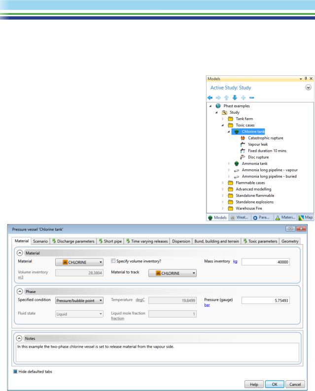
The input dialog for the Chlorine tank Equipment item
In the Models tab section of the Study Tree, expand the Toxic cases folder, and then double-click on the icon for the Pressure Vessel Equipment item named Chlorine tank. The Pressure Vessel Equipment input dialog will open as shown below.
The dialog contains a large number of input fields organised over nearly ten tab sections, but you will not normally enter data in every section. For an Equipment item, the most important inputs are in the Material tab section, which covers the process material and operating conditions. Almost all of the fields in the other tab sections are also present in the Scenario dialogs, and you would set a value in the Equipment dialog if you want the value to be used as the default value for all of the Scenarios under that Equipment item.
Describing every item of input data is beyond the scope of this tutorial. However, you can get a description from the online Help that is included with the program.
| PHAST | April 2018 | www.dnvgl.com/software |
Page 9 |

Every input dialog contains a Help button at the bottom right. When you click on this button, the Help will appear in a separate window, as shown.
The Help Window will be displaying a description of the current tab section, but you can use the links inside the topic and the Contents, Index and Search tabs to reach any topic in the Help system and gain a full understanding of the way that the input data will be used in the calculations and the appropriate values that you should set for the hazardous events that you want to model.
After you have finished exploring the Chlorine tank equipment item’s input dialog, click on Cancel to close the input dialog without saving any changes you might have made. If you wish, you can move to the other tab sections in the Study Tree and explore the input dialogs for other types of data.
The Grid View allows you to work on input data for multiple items
The input dialogs allow you to work on the input data for a single item at a time, and the Help button and the organisation of the tab sections mean that the dialogs are the best way to work on data when you are still becoming familiar with the details of the input data.
However, once you have become familiar with the data, you may find the Grid View useful, as a method of working with input data that allows you to view and edit the data for more than one item at a time. The Grid View appears in a separate tab section in the Document View area, i.e. in the same area as the GIS Input view.
To view the data for both of the Pressure Vessel Equipment items under the Toxic cases folder, take the following steps:
1.Select the Toxic cases folder in the tree.
2.In the Grid View, bring up the list and select Pressure vessel from the list as shown.
This list is known as the “filter list”, and it allows you to choose the type of item whose data you want to view in the area below the toolbar.
| PHAST | April 2018 | www.dnvgl.com/software |
Page 10 |