

The Study Tree pane
The Study Tree pane allows you to organise and edit the input data for your consequence analysis. The pane contains a number of tab sections, each of which covers a different type of input data, and these tab sections are described below.
The Models tab section
You use the Models View to define the hazardous events or Scenarios that you want to model, and to run the calculations for these events and view the results. You can define a range of Scenarios, such as different types of accidental release from different equipment items. This is the main type of input data in the program, and the other types of data can be seen as “background” or “supporting” data.
The data are organised in a tree structure, with four levels of input data:
Level 1: the Workspace 
The workspace node appears at the top of the tree in every tab section of the Study Tree. If you double-click on the icon, a dialog will appear that allows you to set options that will be applied throughout the workspace. The settings will be saved with the workspace file, so you can set different options for different workspaces.
The workspace dialog covers settings that affect the behaviour of the program (e.g. the level of information given in messages), but does not cover any aspect of the definition of hazardous events. The details of hazardous events are defined at lower levels, with nodes that appear only in the Models tab section of the Study Tree.
Level 2: the Study 
The Study level is the level immediately underneath the workspace node. Each new workspace is created with a Study already defined in the Models tab, ready for you to start inserting equipment items under the Study.
The input data for a Study covers two types of setting:
•Values to be used as defaults for equipment items under the Study.
•The selection of the set of Weather conditions and the set of Parameter values to be used in calculations for the Study.
Note: the options for working with Parameters are not available in Phast Lite. None of the references to Parameters in the sections which follow are applicable to Phast Lite.
Weather conditions and Parameter values are defined in separate tabs of the Study Tree that will be described further below. Each new workspace is created with one set of Weathers and one set of Parameters, which are selected by default for each Study. However, if you insert additional sets of Weathers or Parameters, you can edit any Study and change the selection of the Weathers or Parameters for that Study.
| PHAST | April 2018 | www.dnvgl.com/software |
Page 3 |

The combination of Weather Set and Parameters Set that is selected for a particular Study is known as the global context for that Study. One of the main reasons for defining more than one Study in a workspace is to be able to select different global contexts for different Studies.
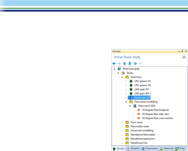
The example file has a single Study called Study.
Level 3: the Equipment item
At the Equipment level, you define the process material and operating conditions. There are five types of item that you can insert at the Equipment level:
•a Pressure Vessel  for modelling releases from pressurised containment
•an Atmospheric Storage Tank  for modelling releases from unpressurised containment
•a Standalones item  for performing detailed modelling of specific hazards such as fire, explosion and pool vaporisation, separate from the modelling of a particular release from containment.
•A Long pipeline  for modelling the time-dependent release from a long pipeline, including the effects of the closure of valves on the pipeline
•A Warehouse  for modelling a fire in a warehouse. The effects of the fire are modelled as a toxic plume which contains a mixture of hydrogen chloride, nitrogen dioxide and sulfur dioxide.
Note: the Standalones and Warehouse Equipment items are not available in Phast Lite.
In addition to defining the process material and operating conditions, you can also use the input data for the Equipment item to set default values to be used for the Scenarios underneath the Equipment item.
The Phast example file has a large number of Equipment items. Most are Pressure Vessels, but there are also some Atmospheric Storage Tanks, Long Pipelines, Standalones, and a Warehouse.
The Equipment items have been organised into folders under the Study in order to make the design of the workspace clearer and easier to work with. For example, there is a Tank farm folder, and a Toxic cases folder. You can have any number of levels of folders under a Study and also under an Equipment item, but the folders are not described here as a level in the data-structure as they do not contain any input data for defining the hazardous events.
Level 4: the Scenario
A Scenario is a hazardous event associated with the Equipment item to which it belongs. The types of scenario that you can define under a given equipment item depends on the type of the equipment item:
•Scenarios for a Pressure Vessel: The Scenarios available for a Pressure Vessel in Phast are shown in
the illustration of the Insert menu for the item, as it appears in the right-click menu. These Scenarios model the release of material through all the stages in its dispersion to a harmless concentration. The modelling includes discharge calculations to obtain the release rate and state. Fire, explosion and toxic calculations where applicable, as well as representative effect zones for the dispersing cloud.
Note: the Time varying Scenarios and the User defined source Scenario are not available in Phast Lite.
| PHAST | April 2018 | www.dnvgl.com/software |
Page 4 |