
- •Contents
- •1 An introduction to Phast
- •What to Expect of this Tutorial
- •Starting the program running
- •The main window
- •Opening the Phast example file
- •The Study Tree pane
- •The Models tab section
- •Level 1: the Workspace
- •Level 2: the Study
- •Level 3: the Equipment item
- •Level 4: the Scenario
- •The Weather tab section
- •The Parameters tab section
- •The Materials tab section
- •Pure Components
- •Mixtures
- •Warehouse Materials
- •The Map tab section
- •Bund types
- •Terrain types
- •Building types and Buildings
- •Raster Image Set
- •Viewing input data
- •The input dialog for the Chlorine tank Equipment item
- •The Grid View allows you to work on input data for multiple items
- •Running the calculations and viewing the results
- •Viewing the graphs for the LPG sphere Scenarios
- •Viewing results on the GIS, against the background of map images
- •Viewing the Reports for the Catastrophic rupture Scenario
- •Summary group: Consequence Summary Report
- •Input group: Input Report
- •Equipment group: Discharge Report
- •Equipment group: Dispersion Report
- •Equipment group: Commentary Report
- •Equipment group: Averaging Times Report
- •Equipment group: Dynamic Fireball Report
- •Equipment group: Explosion Report
- •Viewing the results for other types of Scenario
- •The Standalone flammable Scenarios
- •The Standalone explosion Scenarios
- •2 Setting up your own analysis
- •The form of the analysis
- •The Equipment and Scenarios defined in the analysis
- •Creating a new workspace
- •Saving the workspace
- •The contents of a new workspace
- •Setting up the map image
- •Inserting the raster image
- •Ensure that there is a Raster Image Set in the Map tab section
- •Insert a Raster Image inside the Set
- •Placing the image in the GIS Input View
- •Setting the co-ordinates and size of the image
- •The location of the site on the map
- •3 Performing the consequence analysis
- •Making sure the Run mode is set to Consequence
- •Defining the pressure vessel that contains a toxic material
- •Turn on the option to insert Equipment on the GIS
- •Insert a Pressure Vessel Equipment item
- •Setting the input data for the vessel
- •The Material tab section
- •The Toxic parameters tab section
- •The Geometry tab section
- •A Summary of the Input Data
- •Defining a catastrophic rupture scenario
- •Inserting the Scenario
- •Setting the input data
- •Elevation in Scenario tab section
- •Toxic parameters tab section
- •Run the calculations for the Scenario and view the results
- •Viewing the set of Graphs
- •Viewing outdoor toxic lethality results against the map
- •Defining the second scenario: a liquid release from pipework
- •Insert a Time varying short pipe Scenario
- •Supplying the tank shape data for the Pressure Vessel
- •Setting the input data for the Scenario
- •Scenario tab section
- •Material tab section
- •Short pipe tab section
- •Time varying releases tab section
- •Running the discharge calculations
- •Using the averaged discharge results to create a User-defined source Scenario
- •Inserting a Short pipe Scenario and set up the equivalent input data
- •Run the consequence calculations for the Short pipe and view the results
- •Defining the third scenario: toxic vapour from pipework
- •Defining three flammable releases
- •Setting the input data for the propane Equipment item
- •Copying the Equipment item
- •Changing the Material selection
- •Changing the coordinates
- •Setting the input data for the fire modelling
- •Running the consequence calculations and viewing the results
- •Jet Fire Graphs
- •Pool Fire Graphs
- •Fireball Graphs
- •Explosion Graphs
- •Flash Fire Graph
- •Alternative methods for modelling explosions
- •Creating a Folder and Scenarios for the other methods
- •Setting the inputs for the TNT explosion method
- •Setting the inputs for the Multi-Energy explosion method
- •Setting the inputs for the Baker-Strehlow-Tang explosion method
- •Running the calculations and viewing the results
- •Flammable releases from a rail tank wagon
- •Defining a folder and creating the Equipment data node for the wagon
- •Setting the Elevation for the Rupture Scenarios
- •Defining the Leak from the liquid side of the wagon
- •Defining the Fireball Failure under Flame Impingement
- •Defining a Standalones Equipment item
- •Defining a Fireball Scenario
- •Running the calculations and viewing the results
- •Saving the workspace
- •What next?

3 PERFORMING THE CONSEQUENCE ANALYSIS
Making sure the Run mode is set to Consequence
In the Phast product, the Home tab of the Ribbon Bar contains a Mode option, as shown. The calculations are performed in a particular sequence, and this option allows you to choose how far through the sequence you want the calculations to progress when you use the Run option.
The list of options for Mode will always include Discharge and Consequence. You select Discharge if you only want to run the discharge calculations, and Consequence if you want to proceed to the calculations of dispersion and hazardous effects after the discharge calculations are complete. In the illustration above, Mode is set to Consequence.
If you have a license for the 3D Explosion extension, there will be a third option called Effects, which uses the results of the calculations to perform an additional type of analysis. The Effects option will be set by default when you create a new workspace, but these calculations are not relevant to this tutorial and should not be run. Make sure you change the Mode to Consequence before you start the analysis.
Note: in Phast Lite the Run mode is always Consequence and there is no Mode option.
Defining the pressure vessel that contains a toxic material
Move to the Models tab section. You will start by defining the Pressure Vessel Equipment item that contains a toxic material.
The vessel is a sphere with a radius of 3.37 m and volume of 120 m3 and a maximum fill-level of 85%, containing chlorine at saturation conditions and ambient temperature. The sphere is located near the centre of the site and is elevated 4 m above the ground. There is no bund surrounding the sphere.
Turn on the option to insert Equipment on the GIS
In the Settings tab of the Ribbon Bar, check the option to Insert Equipment on GIS. By default this option is turned off, and when you insert an Equipment item the icon will appear immediately in the Study Tree. If you turn the option on, then the Equipment icon will not appear in the Study Tree until you have clicked on the GIS Input View to set the location for the Equipment item.
In this tutorial you will insert the Equipment items on the GIS View in approximately the correct location, and then correct the location as necessary in the input dialog.
Insert a Pressure Vessel Equipment item
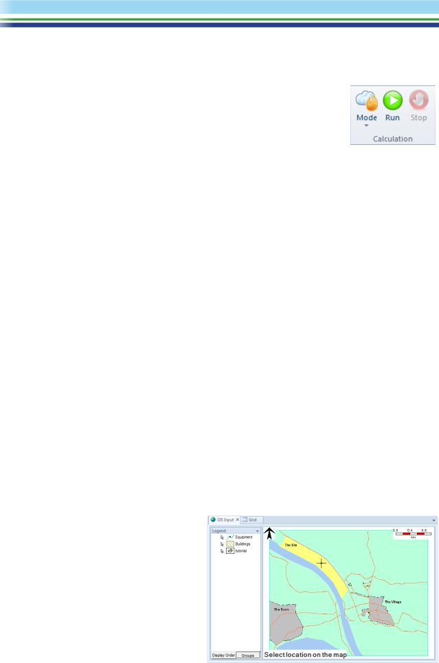
Select the Study, then insert a Pressure vessel using either the right-click menu or the Insert gallery in the Home tab of the Ribbon Bar. The GIS Input View will become selected, the cursor will turn to crosshairs, and you should click at a point near the centre of the site as shown to place the Pressure Vessel.
After you have clicked, an icon will be added to the Study Tree, and a dot will appear in the GIS View to show the location of the Pressure Vessel.
| PHAST | April 2018 | www.dnvgl.com/software |
Page 24 |