

5.3 EXTERIOR PROTOCOLS |
67 |
AS number is added. Thus, despite all the sub-ASes being individually visible within the confederation, the whole confederation still appears as a single AS to any external neighbour. So a single peer network could peer with routers in two different confederation members but the peer network would perceive that it was peering in two locations with the same AS.
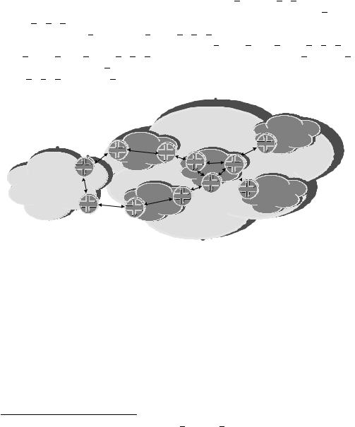
To demonstrate this concept, in Figure 5.5, AS1 has five confederation members (65000, 65001, 65002, 65003 and 65004). A prefix with the AS PATH 10 11 12 is learned via an edge device in sub-AS 65004. It is announced to sub-AS 65000 the AS PATH
(65004) 10 11 12.7 Sub-AS 65000 then forwards the prefix to sub-ASes 65001, 65002 and 65003 with the AS PATH (65000 65004) 10 11 12. Sub-ASes 65001 and 65002 now forward the prefix to AS2. Rather than forwarding 1 (65001 65000 65004) 10 11 12 and 1 (65002 65000 65004) 10 11 12 respectively, they both strip the AS CONFED SEQUENCE from the AS PATH before prepending the confederation’s AS. Thus, both send 1 10 11 12 as the AS PATH.
|
|
AS1 |
AS65003 |
AS65002 |
|
|
|
iBGP |
|
|
eiBGP |
eBGP |
eiBGP |
AS65000 |
|
|
|
iBGP
AS2
iBGP iBGP
 eiBGP
eiBGP
AS65004
iBGP |
AS65001 |
|
|
eiBGP |
|
|
|
|
|
iBGP |
|
|
eBGP |
|
Figure 5.5 BGP confederations
5.3.2AUTHENTICATION OF BGP
Perhaps more than any other protocol, BGP has the potential to be the means of injection of spurious routing information. It also has the capacity for the widest impact. This has been amply demonstrated by the catastrophic events when a router in Florida was subject to a software fault causing deaggregation of CIDR blocks. This routing information was injected back into the global routing tables and caused major problems for significant parts of the Internet. This event caused problems for several hours, even after the network devices at the source of the problem had been completely isolated from the Internet! This demonstrates the degree of vulnerability of BGP to invalid information, although it has
7 The list of numbers in brackets represents an AS CONFED SEQUENCE.
68 |
ROUTING PROTOCOLS |
to be stressed that current authentication mechanisms could not have limited the effects of these faults because the prefixes were being learned from a ‘trusted’ neighbour.
However, similar effects could be produced by a rogue device injecting bogus routing information into unprotected peers on a shared network. Given this vulnerability, it is possibly more important than with any other routing protocol that we authenticate our BGP neighbours.
The authentication mechanism is not actually part of the BGP protocol but is part of the underlying transport protocol. Since TCP does not provide any simple authentication mechanism, the only standardized mechanism for authenticating BGP sessions is MD5 signatures.
5.3.2.1 MD5 Authentication
BGP runs over TCP and can, therefore, use the MD5 authentication mechanisms for TCP messages to authenticate all BGP protocol exchanges. This provides a method to authenticate messages as coming from a trusted source. Given the extent to which the whole Internet can be affected by the injection of spurious information into the global routing table, it is certainly recommended to use this mechanism to ensure that you are peering with the device you think you are peering with. It is important to realize that MD5 authentication provides absolutely no protection against the injection of spurious information by an authenticated source.
5.3.2.2 IPsec Authentication
IPsec has been proposed as a stronger authentication (and potentially encryption) mechanism for BGP messages. IPsec Security Associations are applied to individual BGP sessions. However, since a single security mechanism must be mandated in draft standard RFCs, and MD5 TCP authentication is widely implemented and deployed, IPsec is not mandated as an authentication mechanism in the latest draft specification for the BGP protocol. Even IPsec does not provide protection against the injection of spurious information by an authenticated source. Once authenticated, it is assumed that all data from a particular source is valid. The principles of IPsec were described in Chapter 4.
5.3.3 BGP GRACEFUL RESTART
BGP graceful restart is a negotiable capability. During the process of establishing the relationship, two peers indicate to each other that they are each capable of maintaining their forwarding state across a restart of the routing function. It also informs the neighbour that the router is able to send an End-of-RIB marker upon completion of the initial routing table update. This capability can be independently negotiated for each address family.
When the receiving router detects a reset of the TCP session, it starts a restart timer (the value is agreed during initial negotiation) and marks all the routes learned from the
5.3 EXTERIOR PROTOCOLS |
69 |
restarting routers as stale. Stale routing information should be treated no differently from other routing information. If the restart timer expires, then all stale routes are purged from the routing table of the receiving router.
If the receiving router does not detect the TCP reset, it will receive a new Open message for what it believes to be an existing session. If the two peers have negotiated graceful restart, then the receiving router should reset the original TCP session and use the new session. Since the TCP session has been reset, no Notification message should be sent. The receiving router then goes through the same process of setting the restart timer and marking the routes as stale.
Following the restart, the receiving router will transmit its routes to the restarting router. Once the routing table has been completely sent, the receiving router sends an End-of-RIB marker. The receiving router will also replace any routes marked as stale with identical routes learned from the restarting router.
It is not possible to perform a graceful restart if the TCP session is terminated due to the transmission or receipt of a Notification message. In this case, the standard BGP protocol processes are followed.
While it is clear that graceful restart can significantly reduce the impact of route flapping, it is important to note that it is not without risk. The fact that two routers are maintaining state, which is potentially inconsistent with reality means that it is possible for black holes and transitory routing loops can be created. This risk is generally acceptable given the potentially widespread impact of flapping routes.
It is also worth noting that deploying graceful restart on iBGP sessions in the absence of a similar graceful restart mechanism for the IGP within the autonomous system can reduce the positive benefits of BGP graceful restart.
5.3.4MULTIPROTOCOL BGP
So far, we’ve only discussed BGP, as it was originally designed, for IPv4 unicast NLRI. However, BGP4 has now been extended to carry NLRI for IPv4 multicast, and IPv6 unicast and multicast NLRI. It also supports various forms of NLRI associated with VPNs. Rather than trying to cover all of the different types of NLRI in a single location, each is discussed in description of the use of MBGP in the relevant section.